EP0602655A1 - Verfahren zum Schleifen von Klingen - Google Patents
Verfahren zum Schleifen von Klingen Download PDFInfo
- Publication number
- EP0602655A1 EP0602655A1 EP93120345A EP93120345A EP0602655A1 EP 0602655 A1 EP0602655 A1 EP 0602655A1 EP 93120345 A EP93120345 A EP 93120345A EP 93120345 A EP93120345 A EP 93120345A EP 0602655 A1 EP0602655 A1 EP 0602655A1
- Authority
- EP
- European Patent Office
- Prior art keywords
- grinding
- slitting
- shaft
- slitting blades
- circular
- Prior art date
- Legal status (The legal status is an assumption and is not a legal conclusion. Google has not performed a legal analysis and makes no representation as to the accuracy of the status listed.)
- Withdrawn
Links
- 238000000034 method Methods 0.000 title claims abstract description 45
- 238000007796 conventional method Methods 0.000 abstract description 20
- 230000002093 peripheral effect Effects 0.000 description 6
- 239000000463 material Substances 0.000 description 4
- 230000008602 contraction Effects 0.000 description 3
- 230000003247 decreasing effect Effects 0.000 description 3
- 238000010276 construction Methods 0.000 description 2
- 229910052582 BN Inorganic materials 0.000 description 1
- PZNSFCLAULLKQX-UHFFFAOYSA-N Boron nitride Chemical compound N#B PZNSFCLAULLKQX-UHFFFAOYSA-N 0.000 description 1
- 239000011230 binding agent Substances 0.000 description 1
- 230000007423 decrease Effects 0.000 description 1
- 238000005259 measurement Methods 0.000 description 1
- 238000012986 modification Methods 0.000 description 1
- 230000004048 modification Effects 0.000 description 1
Images


Classifications
-
- B—PERFORMING OPERATIONS; TRANSPORTING
- B24—GRINDING; POLISHING
- B24B—MACHINES, DEVICES, OR PROCESSES FOR GRINDING OR POLISHING; DRESSING OR CONDITIONING OF ABRADING SURFACES; FEEDING OF GRINDING, POLISHING, OR LAPPING AGENTS
- B24B3/00—Sharpening cutting edges, e.g. of tools; Accessories therefor, e.g. for holding the tools
- B24B3/36—Sharpening cutting edges, e.g. of tools; Accessories therefor, e.g. for holding the tools of cutting blades
- B24B3/46—Sharpening cutting edges, e.g. of tools; Accessories therefor, e.g. for holding the tools of cutting blades of disc blades
-
- B—PERFORMING OPERATIONS; TRANSPORTING
- B26—HAND CUTTING TOOLS; CUTTING; SEVERING
- B26D—CUTTING; DETAILS COMMON TO MACHINES FOR PERFORATING, PUNCHING, CUTTING-OUT, STAMPING-OUT OR SEVERING
- B26D7/00—Details of apparatus for cutting, cutting-out, stamping-out, punching, perforating, or severing by means other than cutting
- B26D7/08—Means for treating work or cutting member to facilitate cutting
- B26D7/12—Means for treating work or cutting member to facilitate cutting by sharpening the cutting member
Definitions
- This invention relates to a method of grinding slitting blades, more particularly, to a method grinding slitting blades of a slitter which slits a broad web such as photosensitive material, magnetic record material, pressure sensitive recording paper, thermal recording paper and the like into narrow webs.
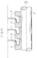
- a slitter which slits a broad web such as photosensitive material, magnetic recording material, pressure sensitive recording paper, thermal recording paper and the like into narrow strips is provided with upper blades 1 and lower blades 2 as shown in Fig. 11, and generally, the lower blades 2 are composed of a plurality of circular slitting blades 2 which are fastened to a shaft at predetermined intervals.
- the circular slitting blade 2 is applied to the slitting for a long time, the slitting ability thereof decreases because of wear and the like, thus, a regular grind is required.
- the peripheral slitting edge 2A and the ventral slitting edge 2B of the circular slitting blade 2 are abutted to oil grindstones 5 and ground so as to have sharpness, and then attached to the shaft 3 again after inspecting the size and the tip of the blade so that the fastening state is adjusted, whereby the attaching accuracy is improved.
- the attaching inaccuracy in which the circular slitting blade 2 is attached to the shaft 3 of the slitter, causes the thrust deflection that the blade tip deflections in the axial direction of the shaft 3 or the radial deflection that it deflects in the rotational direction, when the broad web is slit into narrow strips.
- the thrust deflection occurs, there are problems in that differences in width of the slit strip 7 are generated and the strip 7 twists and is slit, as shown in Fig. 14.
- the conventional method of grinding slitting blades wherein a plurality of the slitting blades 2 are detached from the shaft 3 and ground one by one, and then attached to the shaft 3 again, has a disadvantage in that the attaching accuracy deteriorates.
- the differences are easily generated in the grind accuracy of the respective circular slitting blades 2. That is, in a precision grind, the grind accuracy is influenced by differences in temperature of the circular slitting blade 2 and by slight contraction or expansion thereof by work environment and the like while grinding, so that the factors to deteriorate the grind accuracy may easily increase in the conventional method of grinding, wherein the circular slitting blades 2 are detached from the shaft and ground individually.
- This invention has been developed to eliminate the above-mentioned disadvantages and aims to provide a method of grinding slitting blades, wherein since the grind accuracy can be improved and the high accuracy for attaching can be kept, the slitting accuracy can be improved and the grind lobar and the grind time can be reduced.
- this invention is characterized in that a plurality of slitting blades are fastened to a common shaft through a fastening device, and, in this state, said plurality of circular slitting blades are successively or simultaneously ground by a grinding means.
- the circular slitting blades are successively or simultaneously ground by a grinding means in the state that the circular slitting blades are fastened to a common shaft through a fastening device, therefore, a plurality of processes, which are required in the conventional method of grinding slitting blades, such as the detaching process in that the circular slitting blades are detached from the shaft, the grinding process in that the detached circular slitting blades are ground respectively and the attaching process in that the ground circular slitting blades are attached to the shaft again are not needed, so that only the grinding process is required.
- the moving value of the grinding means (in the horizontal direction) is detected by the detecting means and fed back to the NC controller which controls the grinding means, therefore, the constant grind accuracy can be obtained.
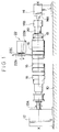
- Fig. 1 shows the grinding apparatus used for the method of the grinding slitting blades according to this invention.
- a shaft driving part 12 is located on one side of a horizontal base 10 and a shaft center pushing part 14 is provided on the other side thereof.
- a plurality of circular slitting blades 16, 16... to be ground are put on the shaft 20 and fastened by the fastening device 18.
- both ends of the shaft 20 provided with the circular slitting blades 16 is supported so that may have the rotational center line shown with X-X in Fig. 1 by which the shaft driving part 12 and the shaft center pushing part 14 are linked.
- the shaft driving part 12 has a built-in motor and a driving axis is rotated thereby, so that the shaft 20 is rotated at a predetermined rotating speed.
- the shaft center pushing part 14 mainly consists of a center 14A projecting to the side of the shaft driving part 12 and a shaft bearing 14B located at the head of the center 14A to bearing-support one end of the shaft 20.
- a grindstone machine 22 is arranged above the shaft 20 supported by the shaft driving part 12 and the shaft center pushing part 14, and it is composed of a grindstone driving part 22B having a built-in motor, a grindstone axis 22C rotated at a predetermined rotating speed by the motor and a cup-shaped grindstone wheel 22A attached to the head of the grindstone axis 22C. Moreover, the grindstone machine 22 moves for a predetermined moving value intermittently in the vertical and horizontal directions as shown by 1- in Fig. 2 by the NC control mechanism not shown. Especially, the moving value in the horizontal direction which exerts a great influence on the grinding accuracy is detected by the magnetic digital read out system and fed back to the NC control mechanism.
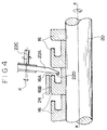
- the NC control mechanism controls the angle ⁇ of the grindstone machine 22, so that the cup-shaped grindstone wheel 22A and the ventral slitting edge end 16A of the circular slitting blade 16 may be abutted to have a predetermined angle.
- CBN grindstone 22D (grindstone which cubic boron nitride grains are united with the binder) clings on the peripheral portion on the grind surface of the cup-shaped grindstone wheel 22A, and is abutted to the vertical slitting edge end 16A of the circular slitting blade 16 to thereby grind.
- the shaft 20 is detached from the slitter, not shown, in the state that the circular slitting blade 16 is fixed thereto, a end of the shaft 20 is supported at the shaft driving part 12 and the other end is supported with the shaft bearing 14B in the shaft center pushing part 14. And, the motor in the shaft driving part 12 is operated to thereby rotate the circular slitting blade at the predetermined rotating speed.
- the grindstone motor of the grindstone machine 22 is operated to thereby rotate the cup-shaped grindstone 22A at the predetermined rotating speed. Then, the grindstone machine 22 is controlled by the NC control mechanism and the following operations are performed, whereby the circular slitting blades 16 are ground one by one successively. That is, the grindstone machine 22 moves downward as 1 in Fig.
- the grindstone machine 22 moves in the axial direction of the shaft 20 as 2 in Fig. 2 by the predetermined moving value, and as shown in Fig. 3, the CBN grindstone 22D of the cup-shaped grindstone wheel 22A is abutted to the vertical slitting edge end 16A of the circular slitting blade 16 to thereby grind the vertical slitting edge end 16A for at the predetermined time.
- the grindstone machine moves as 3 and 4 in Fig.
- the grindstone machine 22 is moved on the predetermined route for the predetermined moving value by the NC control mechanism in the state that a plurality of the circular slitting blades 16 are attached to the shaft 20, whereby the circular slitting blades 16 can be ground successively, therefore, a plurality of processes in which the circular slitting blade 16 is detached from the shaft 20, the detached circular slitting blade 16 is ground individually and then attached to the shaft 20 again, as in the conventional method of grinding slitting blades, are not required, so that the grind can be performed at once.
- the detaching and the attaching of the circular slitting blade are not needed, so that the amount of time can be shortened and the labor needed can be decreased.
- Figs. 5(A), 5(B) and 5(C) show the grind accuracy measured with the tracer-type roughness meter when the circular slitting blade 16 is ground by the method of grinding slitting blades according to this invention
- Fig. 5(A) shows the performance of the shape of the outer peripheral edge end 16B in the circular slitting blade 16
- Fig. 5(B) shows the performance of the shape of the vertical edge end 16A in the circular slitting blade 16
- Fig. 5(C) shows the performance of the roughness of the vertical edge end 16A
- Figs. 6(A), 6(B) and 6(C) show the performance of the circular slitting blade 16 ground by the conventional method of grinding and corresponding to Figs.
- the roughness on the grind surface of the vertical slitting edge end 16A is within 0.6 ⁇ m in the method of grinding according to this invention, however, the maximum difference is 6 ⁇ m in the conventional method of grinding.
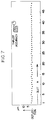
- Fig. 7 shows the performance of the thrust accuracy of the circular slitting blade 16 (the deflection in the axial direction of the shaft 20) which is measured in the state the shaft 20 is attached to the slitter and rotated at the predetermined rotating speed after girding according to the method of girding slitting blade of this invention.
- Fig. 8 shows the performance of the thrust accuracy which is similarly measured in the state that the shaft 20 is attached to the slitter after girding according to the conventional method of girding and attaching the circular slitting blade 16 to the shaft 20.
- the difference can be recognized apparently from Figs. 7 and 8, that is, the thrust accuracy is within 2 ⁇ m in the method of grinding according to this invention, however, the maximum difference is 10 ⁇ m in the conventional method of grinding.
- Fig. 9 shows the performance of the slitting accuracy (the strip width accuracy slit) which is measured by the laser continuous width measuring machine when the broad web is slit into narrow strips in the state that the shaft 20 is attached to the slitter after grinding according to the method of grinding slitting blade of this invention.
- Fig. 10 is a measurement view showing the slitting accuracy which is similarly measured in the state that the shaft 20 is attached to the slitter after grinding according to the conventional method of grinding slitting blade and attaching the circular slitting blade 16 to the shaft 20.
- the difference can be recognized apparently from Figs. 9 and 10, that is, as for the slitting accuracy, the differences of the strip width accuracy is within 5 ⁇ m in the method of grinding according to this invention, however, the maximum difference is 12 ⁇ m in the conventional method of grinding.
- the grind accuracy can be improved in comparison with the conventional method of girding and the excellent attaching accuracy can be kept, therefore, the slitting accuracy can be improved. Therefore, when the web to be slit is a cinefilm, the projection screen can be improved so as to reduce the horizontal deflections.
- one cup-shaped grindstone wheel is attached to the grindstone machine and a plurality of circular slitting blades are ground successively, however, this invention should be not limited to this, a plurality of cup-shaped grindstone wheels may be attached to the grindstone axis of the grindstone machine so as to grind a plurality of circular slitting blades simultaneously.
- the movement of the grindstone machine is controlled by the NC control mechanism, however, a heed handle and the like may be used.
- the circular slitting blades are successively or simultaneously ground by the grinding means in the state that the circular slitting blades are fasten to the fastening device, therefore, the grind accuracy can be improved and the excellent attaching accuracy which the circular slitting blades are attached once can be kept, therefore, the slitting accuracy can be improved.
- the method of grinding slitting blades according to this invention is not necessary to detach the circular slitting blades from the shaft and attach them thereto, therefore, the amount of time needed can be shortened and the labor needed can be decreased.
Landscapes
- Engineering & Computer Science (AREA)
- Mechanical Engineering (AREA)
- Life Sciences & Earth Sciences (AREA)
- Forests & Forestry (AREA)
- Finish Polishing, Edge Sharpening, And Grinding By Specific Grinding Devices (AREA)
- Constituent Portions Of Griding Lathes, Driving, Sensing And Control (AREA)
Applications Claiming Priority (2)
| Application Number | Priority Date | Filing Date | Title |
|---|---|---|---|
| JP337427/92 | 1992-12-17 | ||
| JP33742792A JPH06182659A (ja) | 1992-12-17 | 1992-12-17 | 裁断刃の研磨方法 |
Publications (1)
| Publication Number | Publication Date |
|---|---|
| EP0602655A1 true EP0602655A1 (de) | 1994-06-22 |
Family
ID=18308530
Family Applications (1)
| Application Number | Title | Priority Date | Filing Date |
|---|---|---|---|
| EP93120345A Withdrawn EP0602655A1 (de) | 1992-12-17 | 1993-12-16 | Verfahren zum Schleifen von Klingen |
Country Status (2)
| Country | Link |
|---|---|
| EP (1) | EP0602655A1 (de) |
| JP (1) | JPH06182659A (de) |
Cited By (5)
| Publication number | Priority date | Publication date | Assignee | Title |
|---|---|---|---|---|
| EP1273389A1 (de) * | 2001-07-04 | 2003-01-08 | Eastman Kodak Company | Verfahren zum Schleifen einer Messerwelle |
| EP1273390A1 (de) * | 2001-07-04 | 2003-01-08 | Eastman Kodak Company | Steuervorrichtung zur Ausführung eines Schleifverfahrens für eine Messerwelle |
| CN104771206A (zh) * | 2015-05-07 | 2015-07-15 | 珠海市香之君电子有限公司 | 手术刀片和手术刀的加工方法 |
| CN108818166A (zh) * | 2018-06-29 | 2018-11-16 | 重庆市开州区三中印务有限公司 | 磨刀机 |
| CN110076638A (zh) * | 2019-06-05 | 2019-08-02 | 北京首钢冷轧薄板有限公司 | 一种圆盘剪精度修复方法 |
Families Citing this family (4)
| Publication number | Priority date | Publication date | Assignee | Title |
|---|---|---|---|---|
| JP4685560B2 (ja) * | 2005-09-12 | 2011-05-18 | 日立マクセル株式会社 | 回転刃の研磨装置 |
| CN104999346A (zh) * | 2015-07-27 | 2015-10-28 | 华北电力大学(保定) | 一种下圆盘刀的研刀装置 |
| CN106476062B (zh) * | 2016-11-25 | 2018-07-20 | 浙江东方职业技术学院 | 打磨定宽分切机 |
| CN113414646B (zh) * | 2021-07-05 | 2022-07-05 | 南京硕辉机械制造有限公司 | 一种高速切削金属刀具用智能打磨装置 |
Citations (2)
| Publication number | Priority date | Publication date | Assignee | Title |
|---|---|---|---|---|
| US1580376A (en) * | 1925-04-28 | 1926-04-13 | Jarosz Jan | Bread-slicing machine |
| GB2238494A (en) * | 1989-12-01 | 1991-06-05 | Gd Spa | Grinding device for sharpening a rotary blade |
-
1992
- 1992-12-17 JP JP33742792A patent/JPH06182659A/ja active Pending
-
1993
- 1993-12-16 EP EP93120345A patent/EP0602655A1/de not_active Withdrawn
Patent Citations (2)
| Publication number | Priority date | Publication date | Assignee | Title |
|---|---|---|---|---|
| US1580376A (en) * | 1925-04-28 | 1926-04-13 | Jarosz Jan | Bread-slicing machine |
| GB2238494A (en) * | 1989-12-01 | 1991-06-05 | Gd Spa | Grinding device for sharpening a rotary blade |
Non-Patent Citations (1)
| Title |
|---|
| "Self Sharpening Slitter", IBM TECHNICAL DISCLOSURE BULLETIN., vol. 23, no. 12, May 1981 (1981-05-01), NEW YORK US, pages 5576 - 5577 * |
Cited By (11)
| Publication number | Priority date | Publication date | Assignee | Title |
|---|---|---|---|---|
| EP1273389A1 (de) * | 2001-07-04 | 2003-01-08 | Eastman Kodak Company | Verfahren zum Schleifen einer Messerwelle |
| EP1273390A1 (de) * | 2001-07-04 | 2003-01-08 | Eastman Kodak Company | Steuervorrichtung zur Ausführung eines Schleifverfahrens für eine Messerwelle |
| FR2826899A1 (fr) * | 2001-07-04 | 2003-01-10 | Eastman Kodak Co | Dispositif de controle pour la mise en oeuvre d'un procede de rectification d'un arbre de coupe |
| FR2826894A1 (fr) * | 2001-07-04 | 2003-01-10 | Eastman Kodak Co | Procede de rectification et dispositif de controle d'un arbre de coupe |
| US6544105B1 (en) | 2001-07-04 | 2003-04-08 | Eastman Kodak Company | Control device to implement a grinding process for a knife shaft |
| US6662072B2 (en) | 2001-07-04 | 2003-12-09 | Eastman Kodak Company | Grinding process and control device for a knife shaft |
| CN104771206A (zh) * | 2015-05-07 | 2015-07-15 | 珠海市香之君电子有限公司 | 手术刀片和手术刀的加工方法 |
| CN104771206B (zh) * | 2015-05-07 | 2017-03-08 | 珠海市香之君科技股份有限公司 | 手术刀片和手术刀的加工方法 |
| CN108818166A (zh) * | 2018-06-29 | 2018-11-16 | 重庆市开州区三中印务有限公司 | 磨刀机 |
| CN108818166B (zh) * | 2018-06-29 | 2020-07-14 | 重庆市开州区三中印务有限公司 | 磨刀机 |
| CN110076638A (zh) * | 2019-06-05 | 2019-08-02 | 北京首钢冷轧薄板有限公司 | 一种圆盘剪精度修复方法 |
Also Published As
| Publication number | Publication date |
|---|---|
| JPH06182659A (ja) | 1994-07-05 |
Similar Documents
| Publication | Publication Date | Title |
|---|---|---|
| US5044125A (en) | Method and apparatus for controlling grinding processes | |
| EP0029280B1 (de) | Verfahren und Vorrichtung zum Feststellen der Schleifscheibenabnutzung | |
| CN104029126B (zh) | 用于确认修整工具的构形偏离的方法及相应装备的磨削机 | |
| US5209020A (en) | Method of and apparatus for profiling grinding wheels | |
| EP0602655A1 (de) | Verfahren zum Schleifen von Klingen | |
| JPS62173170A (ja) | 砥石車のツル−イング装置 | |
| GB2270485A (en) | Grinding blade tips of turbine/compressor rotors | |
| JP2000246605A (ja) | 内面研削方法 | |
| US4359841A (en) | Grinding wheel wear detection and dressing method | |
| US5025594A (en) | Method and apparatus for controlling grinding processes | |
| CN106283462B (zh) | 用于橡胶带及滚轴的表面重修的就地磨削设备 | |
| JP2817958B2 (ja) | 研削工程を制御するための改良された装置と方法、および砥石を修正するための装置と方法 | |
| EP0241468B1 (de) | Mit einem abrichtwerkzeug ausgerüsteter schleifmaschinenspindelstock | |
| CN101900665B (zh) | 砂轮研磨参数的估计方法 | |
| JP2708351B2 (ja) | オンラインロール研削装置を備えた圧延機、ロール研削装置及び圧延方法 | |
| US6733365B1 (en) | Method and apparatus for hard machining | |
| US5042206A (en) | Method and apparatus for controlling grinding processes | |
| US4229909A (en) | Tool grinding machine | |
| GB2321026A (en) | Control of machine tools | |
| Uchida et al. | Evaluation of the relationship among dressing conditions using prismatic dresser, dressing resistance, and grinding characteristics | |
| JPH0751967A (ja) | 工作機械の制御方法および制御装置 | |
| SU1196735A1 (ru) | Способ измерени состо ни рабочей поверхности абразивного инструмента | |
| JPH07186044A (ja) | 砥石振れ計測装置および砥石ツルーイング装置 | |
| JP2748569B2 (ja) | 研削加工方法 | |
| JPH0335064B2 (de) |
Legal Events
| Date | Code | Title | Description |
|---|---|---|---|
| PUAI | Public reference made under article 153(3) epc to a published international application that has entered the european phase |
Free format text: ORIGINAL CODE: 0009012 |
|
| AK | Designated contracting states |
Kind code of ref document: A1 Designated state(s): DE NL |
|
| 17P | Request for examination filed |
Effective date: 19941213 |
|
| 17Q | First examination report despatched |
Effective date: 19950411 |
|
| STAA | Information on the status of an ep patent application or granted ep patent |
Free format text: STATUS: THE APPLICATION IS DEEMED TO BE WITHDRAWN |
|
| 18D | Application deemed to be withdrawn |
Effective date: 19951031 |