EP0602665A2 - Equipement de refroidissement et de chauffage pour des véhicules utilisant des alliages absorbants de l'hydrogène - Google Patents
Equipement de refroidissement et de chauffage pour des véhicules utilisant des alliages absorbants de l'hydrogène Download PDFInfo
- Publication number
- EP0602665A2 EP0602665A2 EP93120419A EP93120419A EP0602665A2 EP 0602665 A2 EP0602665 A2 EP 0602665A2 EP 93120419 A EP93120419 A EP 93120419A EP 93120419 A EP93120419 A EP 93120419A EP 0602665 A2 EP0602665 A2 EP 0602665A2
- Authority
- EP
- European Patent Office
- Prior art keywords
- hydrogen absorbing
- hydrogen
- absorbing alloy
- low pressure
- high pressure
- Prior art date
- Legal status (The legal status is an assumption and is not a legal conclusion. Google has not performed a legal analysis and makes no representation as to the accuracy of the status listed.)
- Granted
Links
Images






Classifications
-
- B—PERFORMING OPERATIONS; TRANSPORTING
- B60—VEHICLES IN GENERAL
- B60H—ARRANGEMENTS OF HEATING, COOLING, VENTILATING OR OTHER AIR-TREATING DEVICES SPECIALLY ADAPTED FOR PASSENGER OR GOODS SPACES OF VEHICLES
- B60H1/00—Heating, cooling or ventilating devices
- B60H1/00007—Combined heating, ventilating, or cooling devices
-
- B—PERFORMING OPERATIONS; TRANSPORTING
- B60—VEHICLES IN GENERAL
- B60H—ARRANGEMENTS OF HEATING, COOLING, VENTILATING OR OTHER AIR-TREATING DEVICES SPECIALLY ADAPTED FOR PASSENGER OR GOODS SPACES OF VEHICLES
- B60H1/00—Heating, cooling or ventilating devices
- B60H1/00492—Heating, cooling or ventilating devices comprising regenerative heating or cooling means, e.g. heat accumulators
-
- F—MECHANICAL ENGINEERING; LIGHTING; HEATING; WEAPONS; BLASTING
- F25—REFRIGERATION OR COOLING; COMBINED HEATING AND REFRIGERATION SYSTEMS; HEAT PUMP SYSTEMS; MANUFACTURE OR STORAGE OF ICE; LIQUEFACTION SOLIDIFICATION OF GASES
- F25B—REFRIGERATION MACHINES, PLANTS OR SYSTEMS; COMBINED HEATING AND REFRIGERATION SYSTEMS; HEAT PUMP SYSTEMS
- F25B17/00—Sorption machines, plants or systems, operating intermittently, e.g. absorption or adsorption type
- F25B17/12—Sorption machines, plants or systems, operating intermittently, e.g. absorption or adsorption type using desorption of hydrogen from a hydride
-
- F—MECHANICAL ENGINEERING; LIGHTING; HEATING; WEAPONS; BLASTING
- F01—MACHINES OR ENGINES IN GENERAL; ENGINE PLANTS IN GENERAL; STEAM ENGINES
- F01P—COOLING OF MACHINES OR ENGINES IN GENERAL; COOLING OF INTERNAL-COMBUSTION ENGINES
- F01P11/00—Component parts, details, or accessories not provided for in, or of interest apart from, groups F01P1/00 - F01P9/00
- F01P11/14—Indicating devices; Other safety devices
- F01P2011/205—Indicating devices; Other safety devices using heat-accumulators
Definitions
- the present invention relates to a vehicle using hydrogen absorbing alloys. More particularly, the present invention relates to a vehicle using hydrogen absorbing alloys for cooling and heating equipment.
- each component of the vehicle is mainly heated by means of resistance heating of an electric heater, and is hardly equipped with an independent simple cooling equipment.
- the compressor type of cooling equipment has a pollution problem due to the use of specific freon (R12 for a car air conditioner, and R22 for a refrigerator).
- demand for a portable refrigerator and/or freezer for a car such as a camper has been greatly increased due to the popularization of outdoor leisure.
- the surface temperature of components, especially that of a handle of the vehicle is increased, for example in summer. Therefore, demand is greatly increased for cooling equipment for cooling the air in the passenger compartment and/or each component of the vehicle as soon as possible after the vehicle is started.
- there is also a great demand for heating equipment for rapidly heating the air in the passenger compartment and/or each seat of the vehicle for example in winter.
- the above external heat vapor compressor type ones can advantageously utilize exhaust heat of the engine, but they disadvantageously cost much requiring a complicated manufacturing process so as to have a more precise and airtight structure since the pressure of the inside of the external combustion engine is extremely increased by up to several tens of atmospheres.
- the conventional cooling and heating equipments are generally of vapor compressor type utilizing freon as a heating medium, which causes serious problems of noise and vibration, and destruction of ozone layers, contrary to environmental protection movement.
- a vehicle using hydrogen absorbing alloys includes a plurality of hydrogen absorbing alloy storing vessels for independently storing a plurality of hydrogen absorbing alloys with a different hydrogen equilibrium decomposition pressure, a connecting section for passing hydrogen to and fro among the plurality of hydrogen absorbing alloy storing vessels, and a heating section for heating a low pressure hydrogen absorbing alloy which has the lowest hydrogen equilibrium decomposition pressure among the plurality of hydrogen absorbing alloys, by using combustion heat of fuel of an internal combustion engine or an external combustion engine of the vehicle as a heat source, when the heating section heats the low pressure hydrogen absorbing alloy so that hydrogen is desorbed from the low pressure hydrogen absorbing alloy and then is absorbed by a high pressure hydrogen absorbing alloy of the plurality of hydrogen absorbing alloys, the high pressure hydrogen absorbing alloy having a hydrogen equilibrium decomposition pressure higher than that of the low pressure hydrogen absorbing alloy, exothermic heat generated by absorption of hydrogen by the high pressure hydrogen absorbing alloy is utilized for heating the air in a passenger compartment or a component
- the vehicle using hydrogen absorbing alloys includes at least three hydrogen absorbing alloy storing vessels for independently storing at least three hydrogen absorbing alloys with a different hydrogen equilibrium decomposition pressure, a connecting section for passing hydrogen fro and to among the plurality of hydrogen absorbing alloy storing vessels, and a heating section for heating a low pressure hydrogen absorbing alloy which has the lowest hydrogen equilibrium decomposition pressure among the plurality of hydrogen absorbing alloys, using combustion heat of fuel of an internal combustion engine or an external combustion engine of the vehicle as a heat source, wherein, when the heating section heats the low pressure hydrogen absorbing alloy so that hydrogen is desorbed from the low pressure hydrogen absorbing alloy and then is absorbed by a high pressure hydrogen absorbing alloy of the plurality of hydrogen absorbing alloys, the high pressure hydrogen absorbing alloy having a hydrogen equilibrium decomposition pressure higher than that of the low pressure hydrogen absorbing alloy, exothermic heat generated by absorption of hydrogen by the high pressure hydrogen absorbing alloy is utilized for heating the air in a passenger compartment or a component of the vehicle
- a reversible hydrogen absorption and desorption cycle between the high pressure hydrogen absorbing alloy and the low pressure hydrogen absorbing alloy is performed at a speed in a range from 3 cycles per hour (20 minutes/cycle) to 6 cycles per hour (10 minutes/cycle).
- the heat capacity of the hydrogen absorbing alloy storing vessel is not more than that of the hydrogen absorbing alloy stored therein.
- the void fraction of the hydrogen absorbing alloy storing vessel is in the range of 40 to 75%.
- each of the plurality of hydrogen absorbing alloy storing vessels is in a tube-like shaped, and the longitudinal direction of each of the plurality of hydrogen absorbing alloy storing vessels is horizontally maintained.
- a cooling medium of the fuel of the internal combustion engine or the external combustion engine is used as the heat source for heating the low pressure hydrogen absorbing alloy.
- exhaust gas generated by combustion of the fuel of the internal combustion engine or the external combustion engine is used as the heat source for heating the low pressure hydrogen absorbing alloy.
- the vessel using hydrogen absorbing alloys includes a plurality of hydrogen absorbing alloy storing vessels for independently storing a plurality of hydrogen absorbing alloys with a different hydrogen equilibrium decomposition pressure, a connecting section for passing hydrogen fro and to among the plurality of hydrogen absorbing alloy storing vessels, and a heating section for heating a low pressure hydrogen absorbing alloy which has the lowest hydrogen equilibrium decomposition pressure among the plurality of hydrogen absorbing alloys, using combustion heat of fuel of an internal combustion engine or an external combustion engine of the vehicle as a heat source, when the heating section heats the low pressure hydrogen absorbing alloy so that hydrogen is desorbed from the low pressure hydrogen absorbing alloy and then is absorbed by a high pressure hydrogen absorbing alloy of the plurality of hydrogen absorbing alloys, the high pressure hydrogen absorbing alloy having a hydrogen equilibrium decomposition pressure higher than that of the low pressure hydrogen absorbing alloy, exothermic heat generated by absorption of hydrogen by the high pressure hydrogen absorbing alloy is utilized for heating the air in a passenger compartment or a component of the
- the component is a handle.
- the component is a seat.
- the present invention provides an energy saving type of vehicle with minimization of pollution, in which the exhaust heat of the vehicle is utilized to drive the heat pump using the hydrogen absorbing alloys, and the endothermic reaction and the exothermic reaction of the hydrogen absorbing alloys are utilized for air-conditioning and for heating or cooling each component of the vehicle.
- the invention described herein makes possible the advantage of providing a vehicle using hydrogen absorbing alloys for an energy saving type of cooling and heating equipment with minimization of pollution, without consuming the electric energy of a battery or a generator, nor using polluting materials such as freon as a heating medium but instead efficiently using excess heat or waste heat, the cooling and heating equipment being of a non-freon type and a low noise type not including a vibrating portion, thus contributing to environmental protection.
- Figure 1 is a P-T diagram showing the basic thermodynamic cycles of hydrogen absorbing alloys used in a heat pump according to the present invention.
- Figure 2 shows a structure for a heat pump to be used in a vehicle using hydrogen absorbing alloys according to a first example of the present invention.
- Figure 3 is a graph showing hydrogen pressure versus time for a high pressure hydrogen absorbing alloy and a low pressure hydrogen absorbing alloy used in the heat pump according to the first example.
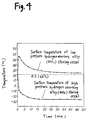
- Figure 4 is a graph showing temperature versus time for the high pressure hydrogen absorbing alloy and the low pressure hydrogen absorbing alloy used in the heat pump during a rapid cooling mode according to the first example.
- Figure 5 is a P-T diagram for various representative hydrogen absorbing alloys used in the heat pump of the present invention.
- Figure 6 shows a structure for a heating equipment for a seat of a vehicle according to a third example of the present invention.
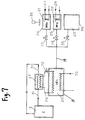
- Figure 7 shows a structure for a heat pump to be used in a vehicle using hydrogen absorbing alloys according to a fourth example of the present invention.
- Figure 8 shows a structure for a heat pump to be used in a vehicle using hydrogen absorbing alloys according to a second example of the present invention.
- Figure 9 is a P-T diagram showing the basic thermodynamic cycles of hydrogen absorbing alloys used in the heat pump during a heating mode according to the fourth example.
- Figure 10 is a P-T diagram showing the basic thermodynamic cycles of hydrogen absorbing alloys used in the heat pump during a cooling mode according to the fourth example.
- Figure 11 shows a structure of a vehicle using hydrogen absorbing alloys according to a second example of the present invention.
- Some kinds of metals and alloys rapidly and reversibly absorb and desorb an extremely large amounts of hydrogen at temperatures over a wide range from about -100°C to about +700°C.
- Such kinds of metals and alloys are herein referred to as hydrogen absorbing alloys.
- a large quantity of heat of reaction is generated while hydrogen is absorbed by or desorbed from such hydrogen absorbing alloys.
- heat of reaction generated by absorption of hydrogen is called exothermo (which heats the ambient air), and that generated by desorption of hydrogen is called endothermo (which cools the ambient air).
- exothermo which heats the ambient air
- endothermo which cools the ambient air.
- Such principles can be utilized for manufacturing cooling and heating equipment using hydrogen absorbing alloys, such as a heat pump to be used in a vehicle using hydrogen absorbing alloys.
- two kinds of hydrogen absorbing alloys having a different hydrogen equilibrium decomposition pressure i.e., a low pressure hydrogen absorbing alloy and a high pressure hydrogen absorbing alloy are used together so as to pass hydrogen between them utilizing a differential in the hydrogen equilibrium decomposition pressures thereof.
- the hydrogen equilibrium decomposition pressure is well known as a plateau pressure of Pressure-Composition-Temperature (P-C-T) characteristics of hydrogen absorbing alloys.
- P-C-T Pressure-Composition-Temperature
- the heat pump using the hydrogen absorbing alloys can be utilized for heat amplification, cooling, and heating systems.
- Such a heat pump can advantageously be operated at temperatures in a wide range of about -100°C to about +700°C, so that it can utilize various kinds of heat including low-temperature heat such as solar energy, and high-temperature heat such as industrial exhaust heat and exhaust heat of an engine. Furthermore, the heat pump can minimize noise and pollution.
- the coefficient of performance (COP) of the heat pump can be represented as a ratio of an effective heat capacity to a total applied heat capacity.
- a multi-effect type of absorption refrigerating machine or the like has been proposed.
- Figure 1 is a thermodynamic diagram in terms of inverse numbers of absolute temperatures and hydrogen equilibrium decomposition pressures, a so called P-T diagram, of two kinds of hydrogen absorbing alloys (a low pressure hydrogen absorbing alloy MH1 and a high pressure hydrogen absorbing alloy MH2), showing how the heat pump using the hydrogen absorbing alloys was operated.
- a solid line drawn on the side of lower pressures (higher temperatures) in Figure 1 shows an operation of the low pressure hydrogen absorbing alloy MH1 and a solid line drawn on the side of higher pressures (lower temperatures) shows an operation of the high pressure hydrogen absorbing alloy MH2.
- the lower pressure hydrogen absorbing alloy MH1 exothermically absorbs hydrogen
- the low pressure hydrogen absorbing alloy MH1 is heated by high temperature exhaust heat or the like and is allowed to endothermically desorb hydrogen.
- the high pressure hydrogen absorbing alloy MH2 exothermically absorbs hydrogen
- the high pressure hydrogen absorbing alloy MH2 endothermically desorbs hydrogen, which is then absorbed by the low pressure hydrogen absorbing alloy MH1, thus returning to the point a .
- the endothermic reaction of the high pressure hydrogen absorbing alloys MH2 at the point d is utilized for a cooling system, while the exothermic reaction of the low pressure hydrogen absorbing alloy MH1 at the point a is utilized for a heating system.
- ⁇ P H1 and ⁇ P H2 each denote a difference of hydrogen pressures between the two kinds of hydrogen absorbing alloys MH1 and MH2, at respective reaction starting time.
- P H (a maximum pressure at a maximum temperature)
- P M an operation pressure of the high pressure hydrogen absorbing alloy MH2 at ambient temperature
- P L an operation pressure of the low pressure hydrogen absorbing alloy MH1 at ambient temperature
- P C an operation pressure of the high pressure hydrogen absorbing alloy MH2 during a cooling mode
- Laves phase alloys were found to be preferable for use in the present invention, the Laves phase alloys being represented by AB ⁇ (wherein, A is one or more elements selected from the group consisting of Ti, Zr, and Hf, B is one or more elements selected from the group consisting of Mn, V, Fe, Ni, Cr, Co, Cu, Zn, Al, Si, Nb, Mo, W, Mg, Ca, Y, Ta, Pd, Ag, Au, Cd In, Sn, Bi, La, Ce, Mm, Pr, Nd, Th, and Sm, ⁇ is in a range of 1.3 to 2.9, Mm is a mixture of rare earth element (lanthanoids), and A and B are different elements), and having a crystal structure which belongs to hexagonal crystal system of C14 (MgZn2) type or cubic crystal system of C15 (MgCu2) type.
- A is one or more elements selected from the group consisting of Ti, Zr, and Hf
- B is one or more elements selected from the group
- Ca or Mm alloys having an AB5 type crystal structure (wherein A and B are different elements), more preferably those having a CaCu5 type crystal structure were found to be suitable in the present invention.
- Such alloys reversibly absorbed and desorbed a large amount of hydrogen rapidly and readily at temperatures not higher than 700°C, and generated heat of reactions was large in quantity.
- FIG. 2 schematically shows a structure for a heat pump to be used in a vehicle using hydrogen absorbing alloys according to the present example.
- the heat pump using the hydrogen absorbing alloys of the present example uses two or more pairs of hydrogen absorbing alloys having a different hydrogen equilibrium decomposition pressure (the low pressure hydrogen absorbing alloy MH1 and the high pressure hydrogen absorbing alloy MH2).
- a first pair of a low pressure hydrogen absorbing alloy MH1 1a and a high pressure hydrogen absorbing alloy MH2 2a and a second pair of a low pressure hydrogen absorbing alloy MH1 1b and a high pressure hydrogen absorbing alloy MH2 2b are used.
- the first and second pairs are connected to each other by pipings 4a and 4b .
- the low pressure hydrogen absorbing alloys MH1 1a and MH1 1b are stored at hydrogen absorbing alloy storing vessels 5a and 5b , respectively.
- the high pressure hydrogen absorbing alloys MH2 2a and MH2 2b are stored in hydrogen absorbing alloy storing vessels 6a and 6b , respectively.
- the hydrogen absorbing alloy storing vessels 5a , 5b , 6a , and 6b each have a heat exchanging function.
- a connecting portion between the hydrogen absorbing alloy storing vessel 5a and the piping 4a , and a connecting portion between the hydrogen absorbing alloy storing vessel 6a and the piping 4a are each provided with a filter 12a for preventing the hydrogen absorbing alloy powders from flowing out.
- a connecting portion between the hydrogen absorbing alloy storing vessel 5b and the piping 4b , and a connecting portion between the hydrogen absorbing alloy storing vessel 6b and the piping 4b are each provided with a filter 12b for preventing the hydrogen absorbing alloy powders from flowing out.
- the pipings 4a and 4b are provided with hydrogen flow adjusting valves 7a and 7b , respectively.
- the low pressure hydrogen absorbing alloy MH1 1a is provided with a heating medium tube 11 for introducing exhaust heat of an internal combustion engine 3 of the vehicle.
- the low pressure hydrogen absorbing alloy MH1 2a is provided with a heating medium tube 10 for releasing the heat generated by the high pressure hydrogen absorbing alloy MH1 2a .
- the high pressure hydrogen absorbing alloy MH2 2a is provided with a radiating fan 8 for radiating the heat generated by the high pressure hydrogen absorbing alloy MH2 2a .
- the high pressure hydrogen absorbing alloy MH2 2b is provided with a cold air blowing fan 9 for introducing cold generated by the high pressure hydrogen absorbing alloy MH2 2b into a passenger compartment of the vehicle.
- thermodynamic cycle of the first and second pairs of hydrogen absorbing alloys is shifted by half-cycle (herein, a cycle of a ⁇ b ⁇ c ⁇ d ⁇ a is referred to as one cycle), so that the heat pump to be used in the vehicle using hydrogen absorbing alloys can be successively operated.
- the first pair of the low pressure hydrogen absorbing alloy MH1 1a and the high pressure hydrogen absorbing alloy MH2 2a is operated at a half cycle of b ⁇ c
- the second pair of the low pressure hydrogen absorbing alloy MH1 1b and the high pressure hydrogen absorbing alloy MH2 2b is operated at a half cycle of d ⁇ a
- the first and second pairs have the substantially the same structure. For simplicity of explanation, components not relating to operations described herein are omitted.
- the low pressure hydrogen absorbing alloy MH1 1a is heated using exhaust gas of the engine 3 as a heat source. Hydrogen desorbed from the low pressure hydrogen absorbing alloy MH1 1a is absorbed by the high pressure hydrogen absorbing alloy MH2 2a . Heat generated at this time is removed by the radiating fan 8 (see the cycle b ⁇ c of Figure 2 ). Subsequently, the low pressure hydrogen absorbing alloy MH1 1b is cooled by the use of the heating medium tube 10 so that hydrogen is desorbed from the high pressure hydrogen absorbing alloy MH2 2b . Consequently, the cold generated by the desorption of hydrogen is introduced into the passenger compartment of the vehicle by the cold air blowing fan 9 for cooling the air in the passenger compartment (see the cycle d ⁇ a of Figure 2 ).
- the hydrogen absorbing alloys MH1 and MH2 were both Laves phase alloys having a crystal structure which belongs to hexagonal crystal system of C14 type. Each hydrogen absorbing alloy was mechanically broken into pieces so as to have an average diameter of 100 ⁇ m and stored in the hydrogen absorbing alloy storing vessel having a heat transfer function so that the vessel would have a void fraction of about 50%.
- the two kinds of alloys were independently subject to an initial activation.
- Each of the hydrogen absorbing alloys was allowed to desorb hydrogen using an oil-sealed rotary vacuum pump for three hours, and thereafter it was filled with hydrogen at a pressure of 45 atmospheres. After the repetition of such an operation, both of the hydrogen absorbing alloys could be made to readily absorb hydrogen within one hour.
- An exhaust gas of the engine 3 was used as the heat source.
- the heat source could be made to have a temperature of about 500°C, and energy power of about 3.5 kW.
- the exhaust gas was cooled to a temperature of about 400°C, and then was supplied to the low pressure hydrogen absorbing alloy MH1.
- the hydrogen equilibrium decomposition of the low pressure hydrogen absorbing alloy MH1 of ZrMn 1.5 Cr 0.5 was about 35 atmospheres.
- the low pressure hydrogen absorbing alloy MH1 was cooled by the heating medium tube 10 using outside air down to a temperature of 45°C
- the high pressure hydrogen absorbing alloy MH2 was cooled by the radiating fan 8 using outside air down to a temperature of 45°C.
- the absorption pressure of the low pressure hydrogen absorbing alloy MH1 was 0.01 atmosphere, and that of the high pressure hydrogen absorbing alloy MH2 was 16 atmospheres.
- the high pressure hydrogen absorbing alloy MH2 blew off air at a temperature of 0°C, and the vessel for storing the high pressure hydrogen absorbing alloy MH2 had a temperature of -5°C.
- the hydrogen equilibrium decomposition pressure of the high pressure hydrogen absorbing alloy MH2 was 2 atmospheres, and heat of reaction thereof was about 50 kcal/kg.
- An apparent specific gravity of the alloy was about 3.0, a void fraction (porosity of materials excluding hydrogen absorbing alloy) of the vessel was 50%, and the volume of the hydrogen absorbing alloy storing vessel was about 20 liters.
- the void fraction of the hydrogen absorbing alloy storing vessel will be described.
- the hydrogen absorbing alloy was expanded in the volume by about 15% or more according to absorption of hydrogen, and was rapidly heated by the heat of reaction. Therefore, the repetition of the thermodynamic cycle makes the hydrogen absorbing alloy powders consolidated and sintered, which is prone to lead to the destruction of the hydrogen absorbing alloy vessel.
- the hydrogen absorbing capacity of the hydrogen absorbing alloy was lowered since the volume expansion of the hydrogen absorbing alloy was restricted by the limitation of the hydrogen absorbing alloy storing vessel.
- the void fraction of the hydrogen absorbing alloy storing vessel should be in the range of 40 to 75%.
- the ratio of the heat capacity of each hydrogen absorbing alloy to that of each hydrogen absorbing alloy storing vessel is preferably: heat capacity of the hydrogen absorbing alloy storing vessel/heat capacity of the hydrogen absorbing alloy ⁇ 1.0. Otherwise, much more calories will be required for heating or cooling the vessel itself, thereby reducing the COP, and thus the hydrogen absorbing alloy becomes uneconomic in practical use.
- Table 1 shows the relationship between the cycle time (operating speed) and the cooling characteristics of the heat pump. As is apparent from Table 1, the slower the operating speed is (the longer the cycle time is), the higher the COP becomes. However, when the operating speed is too much slowed down, the cooling output per hour is contrarily lowered. Generally, the increment in the reaction rate corresponds to the decrement in the operating speed of the heat pump, relatively. Therefore, the use of the hydrogen absorbing alloy having a higher reaction rate results in a high COP value, thus reducing the required amount of alloy. However, when the reaction rate of the hydrogen absorbing alloy is too much high, a cooling output per hour is contrarily lowered.
- FIG 11 shows a structure of a vehicle using hydrogen absorbing alloys according to a second example of the present invention.
- the vehicle uses a heat pump using hydrogen absorbing alloys for a rapidly cooling equipment for a handle of the vehicle.
- the heat pump utilize combustion heat of a Stirling engine 43 as a heat source for heating a low pressure hydrogen absorbing alloy MH1 41 .
- a high pressure hydrogen absorbing alloy MH2 42 is filled in a handle 40 for outputting cold.
- FIG 8 shows an exemplary structure for the heat pump to be used in the vehicle using hydrogen absorbing alloys applied to the rapidly cooling equipment for the handle of the vehicle according to the second example of the present invention.
- combustion heat of a Stirling engine 43 (which is one of the external combustion engines) is introduced into a low pressure hydrogen absorbing alloy MH1 41 by a seamless pipe made of copper phosphate 44 (weight: 2.4 kg) through a cooling medium, thereby obtaining a heat source having a temperature of about 150°C.
- An inner fin tube 47 inside a handle 40 is filled with a high pressure hydrogen absorbing alloy MH2 42 for outputting cold.
- the inner fin tube 47 is made of copper and is provided with an aluminum fin.
- a filter 48 (average diameter of openings: about 0.5 ⁇ m) is provided for preventing hydrogen absorbing alloy powders from flowing out.
- the low pressure hydrogen absorbing alloy MH1 41 and the high pressure hydrogen absorbing alloy MH2 42 are connected to each other via a capillary tube 45 .
- the low pressure hydrogen absorbing alloy MH1 41 2 kg of Ti 0.35 Zr 0.65 Mn 1.2 Cr 0.8 Co 0.2 was used, while, as the high pressure hydrogen absorbing alloy MH2 42 , 2 kg of Ti 0.8 Zr 0.2 Mn 0.8 Cr 1.2 was used.
- the heat of reaction of the low pressure hydrogen absorbing alloy MH1 41 was 114 kcal, and that of the high pressure hydrogen absorbing alloy MH2 42 was 129 kcal.
- the low pressure hydrogen absorbing alloy MH1 41 had hydrogen equilibrium decomposition pressure of 0.4 atmospheres and a reaction rate of 2.5 liter/g ⁇ min at a temperature of 30°C.
- the void refraction of the vessel for storing the low pressure hydrogen absorbing alloy MH1 41 was about 70%.
- the high pressure hydrogen absorbing alloy MH2 42 had hydrogen equilibrium decomposition pressure of 11 atmospheres and a reaction rate of 1.5 liter/g ⁇ min at a temperature of 30°C.
- the void refraction of the vessel for storing the high pressure hydrogen absorbing alloy MH2 was about 50%.
- the high pressure hydrogen absorbing alloy MH2 42 for outputting heat is buried in the handle 40 to be cooled down, thereby achieving much more excellent heat efficiency than a conventional method in which a handle is indirectly cooled or heated using a heating medium.
- the use of the filter is effective in preventing the powders from flowing out, and fixing the powders.
- the heat capacity of the low pressure hydrogen absorbing alloy storing vessel was about 190 cal/deg. which was lower than that of the low pressure hydrogen absorbing alloy stored therein, and that of the high pressure hydrogen absorbing alloy storing vessel was about 200 cal/deg. which was lower than that of the high pressure hydrogen absorbing alloy stored therein.
- the sensible heat loss of each hydrogen absorbing alloy storing vessel was relatively small (about 10% of the heat of reaction of each hydrogen absorbing alloy). On the contrary, when the high pressure hydrogen absorbing alloy storing vessel had a heat capacity of about 380 cal/deg., the sensible heat loss due to the hydrogen absorbing alloy storing vessel was not less than about 30%.
- the heat capacity of the hydrogen absorbing alloy storing vessel should be less than that of the hydrogen absorbing alloy stored therein (i.e., the heat capacity ratio of the heat capacity of the hydrogen absorbing alloy storing vessel to that of the hydrogen absorbing alloy stored therein should be not more than 1.0), in order not to increase the heat loss due to the vessel.
- the longitudinal direction of each hydrogen absorbing alloy storing vessel should be maintained horizontally rather than vertically in order to prevent the hydrogen absorbing alloy from consolidating and improve the durability thereof, which is also true for Example 1.
- Figure 3 is a graph showing hydrogen pressures versus time with respect to two kinds of the hydrogen absorbing alloys MH1 and MH2. As shown in Figure 3 , the hydrogen pressures changed rapidly, which indicates that the rate of the absorption and desorption reaction is higher.
- Figure 4 is a graph showing temperature versus time for the low pressure hydrogen absorbing alloy MH1 and the high pressure hydrogen absorbing alloy MH2 used in the heat pump. As shown in Figure 4 , 1 minute later after the cooling mode starts, the high pressure hydrogen absorbing alloy MH2 cooled down to a temperature of -9.7°C, 2 minutes later, to a temperature of -13.1°C, and finally 20 minutes later, to a temperature of -25.2°C.
- the equipment of the present example has an extremely high cooling rate, and thus it has more excellent cooling characteristics compared with the prior art.
- the heat source is obtained by using the exhaust gas and the cooling medium, but the same effects can be obtained even if the heat source is directly obtained from a combustion chamber.
- FIG. 5 shows a P-T diagram for various representative hydrogen absorbing alloys to be used for the heat pump of the present invention.
- the representative hydrogen absorbing alloys are selected among Laves phase alloys which are represented by AB ⁇ (wherein, A is one or more elements selected from the group consisting of Ti, Zr, and Hf, B is one or more elements selected from the group consisting of Mn, V, Fe, Ni, Cr, Co, Cu, Zn, Al, Si, Nb, Mo, W, Mg, Ca, Y, Ta, Pd, Ag, Au, Cd In, Sn, Bi, La, Ce, Mm, Pr, Nd, Th, and Sm, ⁇ is in a range of 1.3 to 2.9, Mm is a mixture of rare earth element (lanthanoids), and A and B are different elements), and have a crystal structure which belongs to hexagonal crystal system of C14 type or cubic crystal system of C15 type. All of these representative hydrogen absorbing alloys were found to have excellent characteristics. Among them, C14 type
- Table 2 shows composition formulas of representative hydrogen absorbing alloys to be used in the present invention, together with their respective absorbed hydrogen volumes (ml/g), desorbed hydrogen volumes (ml/g), stability of equilibrium decomposition pressure, and relative hysteresis characteristics.
- O shows Excellent
- ⁇ shows Very Good
- ⁇ shows Good.
- evaluation was carried out only for hydrogen absorbing alloys desorbing hydrogen in a volume of 100 ml/g or more.
- the Laves phase alloys AB ⁇ (1.3 ⁇ ⁇ ⁇ 2.9) (alloy number 1 to 44) were found to have excellent characteristics.
- alloys AB ⁇ ( ⁇ > 2.9) were found to desorb much more hydrogen but absorb much less hydrogen.
- alloys AB ⁇ ( ⁇ ⁇ 1.3) were found to absorb much more hydrogen, but desorb much less hydrogen.
- alloys in which the atom number ratio of B element to A element was about 5.0 alloys in which the atom number ratio of B element to A element was about 5.0 (alloy number 45 to 48) had excellent characteristics, and especially alloys having CaCu5 type crystal structure of Ca system (A site being Ca) and Mm system (A site being Mm) had more excellent characteristics.
- Figure 6 shows a structure for a heating equipment for a seat of a vehicle according to a third example of the present invention.
- the combustion heat of an internal combustion engine 3 can be introduced into a low pressure hydrogen absorbing alloy MH1 13 via a cooling medium tube 17 .
- the low pressure hydrogen absorbing alloy MH1 13 is connected to a high pressure hydrogen absorbing alloy MH2 14 via hydrogen conduits 16a and 16b .
- the heat of reaction generated by the low pressure hydrogen absorbing alloy MH1 13 or the high pressure hydrogen absorbing alloy MH2 14 is introduced into a heating medium tube 50 via a heating medium tube 18a or 19 .
- By operating switching valves 51 and 52 either the heating medium tube 18a or the heating medium tube 19 is made to connect to the heating medium tube 50 .
- the heat of reaction of the high pressure hydrogen absorbing alloy MH2 14 and the low pressure hydrogen absorbing alloy MH1 13 was introduced into each seat 15 via the heating medium tubes 19 and 18a .
- vessels for storing the hydrogen absorbing alloys may be directly mounted on each seat so that the seat can be heated more rapidly.
- Figure 7 shows a structure for a cooling and heating equipment in which a hydrogen gas storing vessel is arranged in parallel to the high hydrogen absorbing alloy MH2.
- the exhaust heat of the engine 3 is utilized as a heat source, and is introduced into a heat exchanger 37 via a heating medium tube 31 .
- an opening valve 32 for the heating medium is opened, the heat source is introduced into the low pressure hydrogen absorbing alloy MH1 20 by the heating medium flowing through a heating medium tube 29 , thereby heating the low pressure hydrogen absorbing alloy MH1 20 up to a temperature of 150°C.
- a high pressure hydrogen absorbing alloy MH 2a 21 and a high pressure hydrogen absorbing alloy MH 2b 22 are stored in hydrogen absorbing alloy storing vessels 24 and 25 , respectively.
- the hydrogen equilibrium decomposition pressure of the high pressure hydrogen absorbing alloy MH 2a 21 is higher than that of the high pressure hydrogen absorbing alloy MH 2b 22 .
- the high pressure hydrogen absorbing alloys MH 2a 21 and MH 2b 22 output cold or heat, and thus outputted cold or heat is derived via heating medium tube 27 or 28 .
- a hydrogen gas storing vessel 26 is provided on a hydrogen passageway.
- the vessels 24 , 25 , and 26 are each connected to the low pressure hydrogen absorbing alloy MH1 20 via opening valves 33 , 34 , and 35 , respectively.
- a radiating fan 36 is provided for removing heat generated during reverse reaction at the high pressure hydrogen absorbing alloys MH 2a 21 and MH 2b 22 , or for utilizing the heat or cold for a heating or cooling system.
- a heating medium tube 30 is provided for removing heat generated when the low pressure hydrogen absorbing alloy MH1 20 absorbs hydrogen.
- the weight of the low pressure hydrogen absorbing alloy MH1 20 was 40 kg, and those of the high pressure hydrogen absorbing alloys MH 2a 21 and MH 2b 22 were both 15 kg.
- the volume of the hydrogen gas storing vessel 26 was 300 liters, which was twenty five times as much as that of the low pressure hydrogen absorbing alloy MH1 20 .
- a Ti-Mn polycomponent system alloy having a C14 type crystal structure was used.
- FIG. 9 shows basic thermodynamic cycles of hydrogen absorbing alloys used in the heat pump during a heating mode according to the present example.
- the low pressure hydrogen absorbing alloy MH1 20 is heated up to a temperature of 150°C by the exhaust heat of the engine 3 (solid line on the side of the lowest pressure in Figure 9 ), and then desorbed hydrogen is absorbed by the high pressure hydrogen absorbing alloys MH 2a 21 and MH 2b 22 in the hydrogen absorbing alloy storing vessels 24 and 25 .
- only an opening valve 33 is first opened so that the hydrogen of the low pressure hydrogen absorbing alloy MH1 20 is transferred to the high pressure hydrogen absorbing alloy MH 2a 21 , thereby obtaining heat of about 40°C (solid line on the side of the highest pressure of Figure 9 ).
- the thermal output begins to decrease.
- the opening valve 33 is closed and an opening valve 34 is opened, so that the hydrogen can be introduced into the high pressure hydrogen absorbing alloy MH 2b 22 having a hydrogen equilibrium decomposition pressure lower than that of the high pressure hydrogen absorbing alloy MH 2a 21 , thus obtaining heat of about 60°C (solid line shown in the middle of Figure 9 ).
- the opening valve 34 is closed and then the opening valve 35 is opened, so that a hydrogen gas storing vessel 26 previously made empty is filled with hydrogen gas having a pressure of about 10 atmospheres.
- the hydrogen absorption heat generated by the low pressure hydrogen absorbing alloy MH1 20 is utilized as a heat source for heating the engine 3 via the heating medium tube 29 , the heat exchanger 37 , and the heating medium tube 31 , before the engine 3 is driven.
- cold generated by the high pressure hydrogen absorbing alloys MH 2a 21 and MH 2b 22 is removed by the radiating fan 36 .
- a damper (not shown) is switched to determine whether the heat obtained by the radiating fan 36 is utilized in a vehicle or removed outside.
- the opening valve 34 is opened so that the hydrogen is transferred to the low pressure hydrogen absorbing alloy MH1 20 from the high pressure hydrogen absorbing alloy MH 2b 22 , thus obtaining heat of about 40°C at an initial stage, and then obtaining heat of about 80°C at a peak (broken line on the side of the lower pressures of Figure 9 ).
- the opening valve 34 When hydrogen is not released from the high pressure hydrogen absorbing alloy MH 2b 22 any more, the opening valve 34 is closed, and then the opening valve 33 is opened so that hydrogen is introduced from the high pressure hydrogen absorbing alloy MH 2a 21 into the low pressure hydrogen absorbing alloy MH1 20 , thus obtaining heat having a maximum temperature of 100°C (broken line on the side of the higher pressures of Figure 9 ). Next, the opening valve 33 is closed, and the opening valve 35 is opened, so that hydrogen gas having a pressure of 10 atmospheres is transferred from the hydrogen gas storing vessel 26 to the low pressure hydrogen absorbing alloy MH1 and is stored therein, thereby obtaining heat of 150°C at a peak.
- the operation is basically performed in a manner similar to that of the above heating operation. That is, when heating the engine is not necessary, the heat generated by the low pressure hydrogen absorbing alloy MH1 20 is removed at the cooling medium tube 30 , and cold generated by the high pressure hydrogen absorbing alloys MH 2a 21 and MH 2b 22 can be utilized for cooling the components using the radiating fan 36 . In this case, when the engine 3 is at a room temperature, the opening valve 35 is opened, and the pressure of the hydrogen gas in the hydrogen gas storing vessel 26 is made much lower than 1 atmosphere.
- the above operation will be described referring to a P-T diagram of Figure 10 .
- the P-T diagram of Figure 9 shows basic thermodynamic cycles of hydrogen absorbing alloys used in the heat pump during a cooling mode according to the present example.
- the opening valve 34 is opened, so that hydrogen is released from the high pressure hydrogen absorbing alloy MH 2b 22 to the low pressure hydrogen absorbing alloy MH1 20 , thus obtaining heat of about 20°C (solid line shown in the middle of Figure 10 ).
- the opening valve 34 is closed, and the opening valve 33 is opened, so that hydrogen is released from the high pressure hydrogen absorbing alloy MH 2a 21 to the low pressure hydrogen absorbing alloy MH1 20 , thus obtaining heat of 10°C (solid line on the side of higher pressures of Figure 10 ).
- the temperature of the low pressure hydrogen absorbing alloy MH1 20 is increased by absorption of hydrogen, and the hydrogen equilibrium decomposition pressure is gradually increased, and finally, no hydrogen is released from the high pressure hydrogen absorbing alloys MH 2a 21 and MH 2b 22 .
- the opening valve 33 is closed and the opening valve 35 is opened, and simultaneously, the opening valves 34 and 33 are opened in this order, thereby obtaining a low temperature of 5°C.
- the reason is that the pressure of the hydrogen in the hydrogen gas storing vessel 26 is maintained at about 0.1 atmosphere equivalent to the hydrogen equilibrium decomposition pressure of the low pressure hydrogen absorbing alloy MH1 20 at a temperature of 25°C, so that hydrogen is released from the high pressure hydrogen absorbing alloys MH 2a 21 and MH 2b 22 .
- the opening valves 33 and 34 are previously opened, and simultaneously, the opening valve 35 is opened, so that the hydrogen is released from the high pressure hydrogen absorbing alloys MH 2a 21 and MH 2b 22 , thereby rapidly cooling such a component down to about 5°C.
- hydrogen gas can be introduced into the hydrogen gas storing vessel 26 , thereby facilitating the desorption of hydrogen from the high pressure hydrogen absorbing alloys MH 2a 21 and MH 2b 22 .
- the provision of the hydrogen gas storing vessel makes it possible to rapidly perform the heating or cooling operation, and maintain the heating or cooling operation for a long time.
- the reason is that the heat of reaction of the hydrogen absorbing alloy is utilized for performing the heating or cooling operation, but at that time, it disadvantageously works for stopping the reaction, while the hydrogen is flown into or out from the hydrogen gas storing vessel without generating heat of reaction. That is, only the pressure of the hydrogen gas storing vessel and the equilibrium decomposition pressure of the hydrogen absorbing alloy determine the direction of the transfer of the hydrogen. Accordingly, the pressure of the hydrogen storing vessel can be set as desired during the operation of the heat pump.
- the high pressure hydrogen absorbing alloys MH 2a 21 and MH 2b 22 each has a different hydrogen equilibrium decomposition pressure, thus having a different reaction temperature and a different output temperature. Therefore, it is possible to desirably set a thermodynamic cycle, and determine a system structure in accordance with the temperature of the heat source to be used.
- the maximum COP values of the heat pumps of the above-mentioned four examples were all 0.69 during the cooling mode, and 1.32 during the heating mode. These values are represented assuming that input energy is consumed. However, all of the heat pumps utilize the exhaust heat of the engine, which is generally wasted, thereby not necessitating any input energy at all. Thus, according to the present invention, efficient thermal energy for the cooling or heating operation can be obtained from waste energy, thus saving on energy.
- the vehicle of the present invention is novel in that the exhaust heat of the driving source is utilized for the heat pump to be used in the vehicle using hydrogen absorbing alloys. That is, the present invention provides the vehicle using the hydrogen absorbing alloys for the energy saving type cooling and heating equipment with a minimization of pollution, without consuming electric energy, or using a polluting material such as freon as the heating medium but instead efficiently using excess heat or waste heat, the cooling and heating equipment being of a non-freon type and a low noise type not including a vibrating portion, thus contributing to environmental protection.
- components, especially a handle of the vehicle can be rapidly cooled, for example in summer, and components, especially a seat can effectively be heated, for example in winter.
Landscapes
- Engineering & Computer Science (AREA)
- Physics & Mathematics (AREA)
- Mechanical Engineering (AREA)
- Thermal Sciences (AREA)
- General Engineering & Computer Science (AREA)
- Sorption Type Refrigeration Machines (AREA)
Applications Claiming Priority (2)
| Application Number | Priority Date | Filing Date | Title |
|---|---|---|---|
| JP338420/92 | 1992-12-18 | ||
| JP33842092 | 1992-12-18 |
Publications (3)
| Publication Number | Publication Date |
|---|---|
| EP0602665A2 true EP0602665A2 (fr) | 1994-06-22 |
| EP0602665A3 EP0602665A3 (fr) | 1995-01-11 |
| EP0602665B1 EP0602665B1 (fr) | 1997-07-23 |
Family
ID=18317989
Family Applications (1)
| Application Number | Title | Priority Date | Filing Date |
|---|---|---|---|
| EP93120419A Expired - Lifetime EP0602665B1 (fr) | 1992-12-18 | 1993-12-17 | Equipement de refroidissement et de chauffage pour des véhicules utilisant des alliages absorbants de l'hydrogène |
Country Status (3)
| Country | Link |
|---|---|
| US (2) | US5469913A (fr) |
| EP (1) | EP0602665B1 (fr) |
| DE (1) | DE69312437T2 (fr) |
Families Citing this family (20)
| Publication number | Priority date | Publication date | Assignee | Title |
|---|---|---|---|---|
| US5678410A (en) * | 1993-08-06 | 1997-10-21 | Toyota Jidosha Kabushiki Kaisha | Combined system of fuel cell and air-conditioning apparatus |
| DE4410914C2 (de) * | 1994-03-29 | 1996-03-28 | Daimler Benz Aerospace Ag | Vorrichtung zum Abführen von Wärme |
| US6099811A (en) * | 1998-02-13 | 2000-08-08 | Energy Conversion Devices, Inc. | Self-heating metal-hydride hydrogen storage system |
| US6318453B1 (en) * | 2000-04-26 | 2001-11-20 | Energy Conversion Devices, Inc. | Hydrogen cooled hydrogen storage unit having maximized cooling efficiency |
| US6833118B2 (en) * | 2000-12-20 | 2004-12-21 | Texaco Ovonic Hydrogen Systems Llc | Hydrogen storage bed system including an integrated thermal management system |
| US6878353B2 (en) * | 2000-12-20 | 2005-04-12 | Texaco Ovonic Hydrogen Systems Llc | Hydrogen storage bed system including an integrated thermal management system |
| US7254983B2 (en) * | 2001-10-16 | 2007-08-14 | Hera Usa Inc. | Fuel gauge for hydrogen storage media |
| DE10259071B4 (de) * | 2002-07-16 | 2006-05-04 | J. Eberspächer GmbH & Co. KG | Temperiersystem für ein Fahrzeug |
| US6918430B2 (en) * | 2002-08-14 | 2005-07-19 | Texaco Ovonic Hydrogen Systems Llc | Onboard hydrogen storage unit with heat transfer system for use in a hydrogen powered vehicle |
| GB2401669A (en) * | 2003-05-12 | 2004-11-17 | Autoliv Dev | A thermally regulated steering wheel |
| DE10330816A1 (de) * | 2003-07-08 | 2005-01-27 | Still Gmbh | Flurförderzeug mit einem elektrischen Antrieb, einem Brennstoffzellensystem und einer Heizvorrichtung für einen Bedienplatz |
| US7581698B2 (en) * | 2004-04-23 | 2009-09-01 | Airbus Deutschland Gmbh | Method and apparatus for tempering gaseous and/or liquid media in transportation vehicles, particularly in aircraft |
| WO2005119145A1 (fr) * | 2004-05-17 | 2005-12-15 | Hera Usa Inc. | Conditionneur d'air a hydrure mecanique |
| DE102006034194B4 (de) * | 2006-07-24 | 2012-02-23 | Airbus Operations Gmbh | Kombiniertes Kühl- und Heizsystem |
| DE102007004602B4 (de) * | 2007-01-30 | 2009-05-28 | Continental Automotive Gmbh | Heizvorrichtung zum Erhitzen eines Speichers für ein Komplexsalz |
| GB2447040B (en) * | 2007-03-01 | 2009-07-15 | Oxford Instr Superconductivity | A method of operating an adsorption refrigeration system |
| US8997505B2 (en) | 2012-08-16 | 2015-04-07 | Ford Global Technologies, Llc | Motor vehicle climate control system |
| DE102014109580B3 (de) * | 2014-07-09 | 2015-08-06 | Deutsches Zentrum für Luft- und Raumfahrt e.V. | Thermisches Absicherungssystem, Fahrzeug und Verfahren zur thermischen Absicherung eines thermisch abzusichernden Systems |
| KR102322529B1 (ko) * | 2021-05-25 | 2021-11-09 | 김규정 | 열원 공급 장치 및 공기조화 시스템 |
| EP4506302A1 (fr) * | 2023-08-07 | 2025-02-12 | Hyundai Motor Company | Système de stockage et de compression d'hydrogène |
Family Cites Families (18)
| Publication number | Priority date | Publication date | Assignee | Title |
|---|---|---|---|---|
| DE2631359A1 (de) * | 1976-07-13 | 1978-01-19 | Daimler Benz Ag | Verfahren und vorrichtung zum kuehlen von innenraeumen von kraftfahrzeugen |
| DE3047023A1 (de) * | 1980-12-13 | 1982-07-22 | Daimler-Benz Ag, 7000 Stuttgart | Verfahren zum kuehlen von innenraeumen von fahrzeugen mit wasserstoff verbrauchenden kraftmaschinen nach dem kompressionskaelteverfahren |
| JPS57115655A (en) * | 1981-01-06 | 1982-07-19 | Sekisui Chemical Co Ltd | Heat pump apparatus |
| JPS5822892A (ja) * | 1981-08-03 | 1983-02-10 | Kobe Steel Ltd | 熱交換方法及びその装置 |
| JPS5925955B2 (ja) * | 1981-09-17 | 1984-06-22 | 工業技術院長 | 金属水素化物蓄熱装置 |
| US4436539A (en) * | 1981-10-06 | 1984-03-13 | Technion Research And Development Foundation Ltd. | Method and apparatus for air-conditioning by means of a hydrogen heat pump |
| DE3474338D1 (en) * | 1983-07-08 | 1988-11-03 | Matsushita Electric Industrial Co Ltd | Thermal system based on thermally coupled intermittent absorption heat pump cycles |
| JPS61128072A (ja) * | 1984-11-27 | 1986-06-16 | 松下電器産業株式会社 | 金属水素化物ヒ−トポンプ装置 |
| US4599867A (en) * | 1985-01-25 | 1986-07-15 | Retallick William B | Hydrogen storage cell |
| JPS61280345A (ja) * | 1985-06-03 | 1986-12-10 | Sekisui Chem Co Ltd | 急速加熱冷却装置 |
| FR2582790B1 (fr) * | 1985-06-04 | 1987-07-24 | Elf Aquitaine | Procede et dispositif thermochimiques de stockage et destockage de chaleur |
| JPS61285357A (ja) * | 1985-06-11 | 1986-12-16 | 松下電器産業株式会社 | ヒ−トポンプ装置 |
| SE450072B (sv) * | 1985-10-07 | 1987-06-01 | Mekania Verken Ab | Anordning for frankoppling av en termostatstyrd vermeavgivande enhet efter ett forutbestemt antal temperaturpendlingar |
| FR2615602B1 (fr) * | 1987-05-22 | 1989-08-04 | Faiveley Ets | Procede pour produire du froid par reaction solide-gaz et dispositif s'y rapportant |
| JPH01210768A (ja) * | 1988-02-17 | 1989-08-24 | Agency Of Ind Science & Technol | 蓄熱式ヒートポンプ |
| JPH0830632B2 (ja) * | 1988-05-19 | 1996-03-27 | 松下電器産業株式会社 | 間欠作動式加熱器 |
| US4928496A (en) * | 1989-04-14 | 1990-05-29 | Advanced Materials Corporation | Hydrogen heat pump |
| US5048299A (en) * | 1989-10-24 | 1991-09-17 | Retallick William B | Air conditioner for an automobile |
-
1993
- 1993-12-13 US US08/166,505 patent/US5469913A/en not_active Expired - Lifetime
- 1993-12-17 EP EP93120419A patent/EP0602665B1/fr not_active Expired - Lifetime
- 1993-12-17 DE DE69312437T patent/DE69312437T2/de not_active Expired - Fee Related
-
1995
- 1995-07-18 US US08/503,845 patent/US5571251A/en not_active Expired - Lifetime
Also Published As
| Publication number | Publication date |
|---|---|
| EP0602665A3 (fr) | 1995-01-11 |
| US5571251A (en) | 1996-11-05 |
| DE69312437D1 (de) | 1997-09-04 |
| US5469913A (en) | 1995-11-28 |
| DE69312437T2 (de) | 1997-11-06 |
| EP0602665B1 (fr) | 1997-07-23 |
Similar Documents
| Publication | Publication Date | Title |
|---|---|---|
| EP0602665B1 (fr) | Equipement de refroidissement et de chauffage pour des véhicules utilisant des alliages absorbants de l'hydrogène | |
| US5497630A (en) | Method and apparatus for hydride heat pumps | |
| US4111002A (en) | Cyclic desorption refrigerator and heat pump, respectively | |
| US8511111B2 (en) | Automotive adsorption heat pump | |
| Muthukumar et al. | Erratum to “Metal hydride based heating and cooling systems: A review”[International Journal of Hydrogen Energy (2010) 35: 3817–3831] | |
| US4928496A (en) | Hydrogen heat pump | |
| US4623018A (en) | Thermal system based on thermally coupled intermittent absorption heat pump cycles | |
| US4436539A (en) | Method and apparatus for air-conditioning by means of a hydrogen heat pump | |
| US3704600A (en) | Cryogenic refrigerator | |
| US5157938A (en) | Three-stage sorption type cryogenic refrigeration systems and methods employing heat regeneration | |
| US20240151360A1 (en) | Hydrogen supply module and hydrogen supply method | |
| Kumar et al. | Studies on a metal hydride based year-round comfort heating and cooling system for extreme climates | |
| Wimmer et al. | High performance reactor of a metal hydride based cooling system for air-conditioning of fuel cell electric vehicles | |
| US20050274492A1 (en) | Metal hydride based vehicular exhaust cooler | |
| US5174367A (en) | Thermal utilization system using hydrogen absorbing alloys | |
| US4589479A (en) | Hot water supply unit | |
| JPH06235560A (ja) | 水素吸蔵合金利用移動体 | |
| US5048299A (en) | Air conditioner for an automobile | |
| JPH11502583A (ja) | スターリング原理によって作動する熱機関 | |
| JPS621188B2 (fr) | ||
| JPH0749037A (ja) | 水素燃料自動車 | |
| JPS6241138B2 (fr) | ||
| JPH0755284A (ja) | 圧縮式金属水素化物ヒートポンプ | |
| JP3604733B2 (ja) | パルスチューブ冷凍機 | |
| JPS6329183B2 (fr) |
Legal Events
| Date | Code | Title | Description |
|---|---|---|---|
| PUAI | Public reference made under article 153(3) epc to a published international application that has entered the european phase |
Free format text: ORIGINAL CODE: 0009012 |
|
| 17P | Request for examination filed |
Effective date: 19931217 |
|
| AK | Designated contracting states |
Kind code of ref document: A2 Designated state(s): DE |
|
| RIN1 | Information on inventor provided before grant (corrected) |
Inventor name: ADACHI, KINICHI Inventor name: YASUMOTO, EIICHI Inventor name: HATOH, KAZUHITO Inventor name: NIIKURA, JUNJI Inventor name: TANIGUCHI, NOBORU Inventor name: GAMOU, TAKAHARU |
|
| PUAL | Search report despatched |
Free format text: ORIGINAL CODE: 0009013 |
|
| AK | Designated contracting states |
Kind code of ref document: A3 Designated state(s): DE |
|
| 17Q | First examination report despatched |
Effective date: 19960409 |
|
| GRAG | Despatch of communication of intention to grant |
Free format text: ORIGINAL CODE: EPIDOS AGRA |
|
| GRAH | Despatch of communication of intention to grant a patent |
Free format text: ORIGINAL CODE: EPIDOS IGRA |
|
| GRAH | Despatch of communication of intention to grant a patent |
Free format text: ORIGINAL CODE: EPIDOS IGRA |
|
| GRAA | (expected) grant |
Free format text: ORIGINAL CODE: 0009210 |
|
| RAP1 | Party data changed (applicant data changed or rights of an application transferred) |
Owner name: MATSUSHITA ELECTRIC INDUSTRIAL CO., LTD. |
|
| AK | Designated contracting states |
Kind code of ref document: B1 Designated state(s): DE |
|
| REF | Corresponds to: |
Ref document number: 69312437 Country of ref document: DE Date of ref document: 19970904 |
|
| PLBE | No opposition filed within time limit |
Free format text: ORIGINAL CODE: 0009261 |
|
| STAA | Information on the status of an ep patent application or granted ep patent |
Free format text: STATUS: NO OPPOSITION FILED WITHIN TIME LIMIT |
|
| 26N | No opposition filed | ||
| PGFP | Annual fee paid to national office [announced via postgrant information from national office to epo] |
Ref country code: DE Payment date: 20020109 Year of fee payment: 9 |
|
| PG25 | Lapsed in a contracting state [announced via postgrant information from national office to epo] |
Ref country code: DE Free format text: LAPSE BECAUSE OF NON-PAYMENT OF DUE FEES Effective date: 20030701 |