EP0602753A1 - Trépan à disques pour roche et matériaux similaires - Google Patents
Trépan à disques pour roche et matériaux similaires Download PDFInfo
- Publication number
- EP0602753A1 EP0602753A1 EP93203555A EP93203555A EP0602753A1 EP 0602753 A1 EP0602753 A1 EP 0602753A1 EP 93203555 A EP93203555 A EP 93203555A EP 93203555 A EP93203555 A EP 93203555A EP 0602753 A1 EP0602753 A1 EP 0602753A1
- Authority
- EP
- European Patent Office
- Prior art keywords
- cutting disk
- support element
- disk according
- wear tool
- constituted
- Prior art date
- Legal status (The legal status is an assumption and is not a legal conclusion. Google has not performed a legal analysis and makes no representation as to the accuracy of the status listed.)
- Withdrawn
Links
Images

Classifications
-
- E—FIXED CONSTRUCTIONS
- E21—EARTH OR ROCK DRILLING; MINING
- E21B—EARTH OR ROCK DRILLING; OBTAINING OIL, GAS, WATER, SOLUBLE OR MELTABLE MATERIALS OR A SLURRY OF MINERALS FROM WELLS
- E21B10/00—Drill bits
- E21B10/08—Roller bits
- E21B10/12—Roller bits with discs cutters
-
- E—FIXED CONSTRUCTIONS
- E21—EARTH OR ROCK DRILLING; MINING
- E21B—EARTH OR ROCK DRILLING; OBTAINING OIL, GAS, WATER, SOLUBLE OR MELTABLE MATERIALS OR A SLURRY OF MINERALS FROM WELLS
- E21B10/00—Drill bits
- E21B10/46—Drill bits characterised by wear resisting parts, e.g. diamond inserts
- E21B10/50—Drill bits characterised by wear resisting parts, e.g. diamond inserts the bit being of roller type
- E21B10/52—Drill bits characterised by wear resisting parts, e.g. diamond inserts the bit being of roller type with chisel- or button-type inserts
-
- E—FIXED CONSTRUCTIONS
- E21—EARTH OR ROCK DRILLING; MINING
- E21D—SHAFTS; TUNNELS; GALLERIES; LARGE UNDERGROUND CHAMBERS
- E21D9/00—Tunnels or galleries, with or without linings; Methods or apparatus for making thereof; Layout of tunnels or galleries
- E21D9/10—Making by using boring or cutting machines
- E21D9/1006—Making by using boring or cutting machines with rotary cutting tools
- E21D9/104—Cutting tool fixtures
Definitions
- the present invention relates to a cutting disk for rock and similar materials.
- the disk by revolving and cutting along essentially its peripheral edge, makes it possible the rock penetration rate to be maximized.
- the disk is also that portion of the roll which is submitted to the largest stresses, which are such as to cause a rapid wear thereof.
- the wear of the disk requires that the rolls and/or the disk are frequently replaced, an operation which, as a matter of fact, requires that the mill is stopped and the production is discontinued, with the attending personnel being possibly not properly used. Furthermore, one should also consider that a more frequent replacement of the disk may cause damages to the integrity of the other components of the same roll.
- a further purpose is of taking advantage, as far as possible, of the characteristics of the material used, in order to achieve higher disk penetration rates with lower and lower friction on the rock, and, possibly, with minimal values of the moment of inertia.
- a further purpose is of reaching the optimal exploitation of the power of the mill, and reducing the specific energy consumption per each m3 of excavated rock.
- a cutting disk for rock and similar materials which is constituted by a wear tool ring housed on a support element which can be constrained to the casing of a roller of a cutting head for mills, characterized in that said wear tool ring is constituted by a plurality of parts with circular sector shape.
- said support element is constituted by a pair of annular elements positioned on opposite sides relatively to the wear tool.
- any worn off parts can be rapidly replaced, with the surfaces of the casing on which both the wear tool ring and the support elements are housed, remaining unaltered and in their original condition.
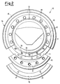
- a cutting disk for rock and similar materials is schematically illustrated, which is generally indicated with 10, and is installed on board of the casing 11 of a roll of a cutting head for mills, suitably linked onto a revolving shaft.
- the disk 10 is composed by two support elements 12, 13, between which a tool ring 14, acting as the cutting element, is installed.
- the ring 14 is constituted by a hard metal, suitably studied for shape and alloy, firmly linked to the support elements 12, 13.
- the tool ring 14 of hard metal is composed by three modular sectors 15, e.g., having a circle-arc shape, and extending over an angle of 120 o , which are equal to each other and interchangeable, in such a way that, once installed, they will form a complete ring.
- the wear tool ring 14 displays a symmetrical cross section and one of such modular sectors 15 is shown in exploded view in Figure 2.
- Said modular sectors 15, or, anyway, the tool ring 14, are is correctly positioned inside a relevant hollow seat 20 peripherally provided on the support element 13, which is made in the form of an enblock ring, and is facing inwards, i.e., opposite to the other support element 12.
- the correct positioning of the modular sector 15 relatively to the support elements 12 and 13 is furthermore accomplished thanks to the presence of elastic pins 16 which can be slid into through-bores 21 provided through the modular sectors 15 and inside blind bores 22 provided inside the support elements 12 and 13.
- the whole positioning of the cutting disk 10 is finally accomplished by lining up through-bores 17 and threaded bores 18 provided through and, respectively, inside both mutually facing support elements 12 and 13, respectively.
- Said support elements 12 and 13 are constrained to each other by entering relevant fastening elements, as screws 19, into the mutually lined-up bores 17 and 18, so as to realize the above said cutting assembly.
- the cutting disk 10 is housed on the casing 11 of the roll and is fastened in its position by means of an elastic ring 23 which can be housed inside a ring groove 24 provided in said casing.
- the tool ring 14 may be made as one single piece, with, however, the problems relating to manufacturing such an enblock piece of hard metal, remaining untouched.
- the support elements 12 and 13 are constituted by anular elements separate from the casing 11 of the roll. More precisely, said support element 13 is made, as said, as one single enblock, ring-shaped piece, and the support element 12 is realized as three mutually equal sectors each of which extends in circle-arc fashion over an angle of 120 o , and all of which, once installed, will form a ring-shaped element. Therefore, the disk 10 will be mounted on the casing 11 of the roll first by inserting the support element 13, then positioning, through the elastic pins 16, the tool ring 14, whether made as one single enblock part, or as a plurality of parts, and finally housing the second support element 12, or the three sectors which constitute it.
- the elastic ring 23 will be positioned inside the groove 24 provided in the casing 11, after fastening the support elements 12 and 13 to each other by means of screws 19.
- one of the support elements e.g., the support element indicated with 13, could be integrated in the casing 11, so as to constitute an enblock piece with it.
- the tool ring 14 of hard metal, or its modular sectors could be directly positioned on their relevant seat 20.
- the end assembly of the cutting disk could be carried out by installing the second support element 12, as a fastenable element to casing 11.
- the removability of the second support element 12 would allow the ring 14 or wear element to be totally or partially replaced, in this case too, without having to dismantle the roll from the mill head.
- Figure 3 displays a further, alternative exemplifying embodiment of the present finding, in which support elements 112 and 113 equal to each other are provided.
- support elements 112 and 113 equal to each other are provided.
- seats 120 are provided which are suitable for housing a tool ring 114.
- the tool ring 114 can be constituted by a plurality of parts with circular sector shape, which are modular and interchangeable.
- the tool ring 114, or its modular portions, are provided with through-bores 122 which can be lined-up to bores 117 and 118 provided through the support elements 112 and 113. In that way, both the linkage between the support elements 112 and 113, and, directly, fastening the tool ring 114 and/or its modular parts, can be accomplished by means of screws 119.
- the wear tool ring 114 has a cross-section in which a side 125 of said cross-section has a not very inclined direction, i.e., a nearly vertical direction, and, on the contrary, the other side 126 extends according to a rather inclined direction.
- a wear tool ring 114 may be given such a shape in order that the wear deriving from the penetration compensates for the wear caused at furrow exiting, producing a self-sharpening action and, above all, reducing the friction undergone by the tool when entering into and leaving from, the material to be cut.
Landscapes
- Engineering & Computer Science (AREA)
- Mining & Mineral Resources (AREA)
- Life Sciences & Earth Sciences (AREA)
- Geology (AREA)
- Environmental & Geological Engineering (AREA)
- General Life Sciences & Earth Sciences (AREA)
- Geochemistry & Mineralogy (AREA)
- Mechanical Engineering (AREA)
- Physics & Mathematics (AREA)
- Fluid Mechanics (AREA)
- Earth Drilling (AREA)
- Excavating Of Shafts Or Tunnels (AREA)
Applications Claiming Priority (2)
| Application Number | Priority Date | Filing Date | Title |
|---|---|---|---|
| IT001069 IT227065Y1 (it) | 1992-12-17 | 1992-12-17 | Disco di taglio per roccia e materiali similari |
| ITMI921069 | 1992-12-17 |
Publications (1)
| Publication Number | Publication Date |
|---|---|
| EP0602753A1 true EP0602753A1 (fr) | 1994-06-22 |
Family
ID=11363192
Family Applications (1)
| Application Number | Title | Priority Date | Filing Date |
|---|---|---|---|
| EP93203555A Withdrawn EP0602753A1 (fr) | 1992-12-17 | 1993-12-16 | Trépan à disques pour roche et matériaux similaires |
Country Status (2)
| Country | Link |
|---|---|
| EP (1) | EP0602753A1 (fr) |
| IT (1) | IT227065Y1 (fr) |
Cited By (4)
| Publication number | Priority date | Publication date | Assignee | Title |
|---|---|---|---|---|
| EP1319797A1 (fr) * | 2001-12-15 | 2003-06-18 | Sandra Duden | Anneau de coupe pour un disque tournant dans une machine de creusement à section partiale et totale |
| WO2004063529A1 (fr) * | 2003-01-10 | 2004-07-29 | Sandra Duden | Anneau de coupe destine a des rouleaux de disques de machines de coupe partielle ou complete |
| CN108138568A (zh) * | 2015-10-30 | 2018-06-08 | 罗宾斯公司 | 用于隧道钻机的夹持环切刀组件 |
| JP2019002178A (ja) * | 2017-06-14 | 2019-01-10 | 株式会社大林組 | 摩耗検知装置 |
Citations (5)
| Publication number | Priority date | Publication date | Assignee | Title |
|---|---|---|---|---|
| US1143275A (en) * | 1914-05-02 | 1915-06-15 | Sharp Hughes Tool Company | Domountable cutting edge for drilling-tools. |
| US3766998A (en) * | 1972-07-17 | 1973-10-23 | Gen Electric | Disc cutter for boring-type mining machine |
| US3981370A (en) * | 1972-06-02 | 1976-09-21 | Hard Metals Limited | Disc cutting unit for use on rock boring machines |
| US4004645A (en) * | 1974-07-31 | 1977-01-25 | Gwilym James Rees | Disc cutting units for use on rock boring machines |
| FR2593548A1 (fr) * | 1986-01-28 | 1987-07-31 | Boart Int Ltd | Disque de coupe pour machine a travailler la roche |
-
1992
- 1992-12-17 IT IT001069 patent/IT227065Y1/it active IP Right Grant
-
1993
- 1993-12-16 EP EP93203555A patent/EP0602753A1/fr not_active Withdrawn
Patent Citations (5)
| Publication number | Priority date | Publication date | Assignee | Title |
|---|---|---|---|---|
| US1143275A (en) * | 1914-05-02 | 1915-06-15 | Sharp Hughes Tool Company | Domountable cutting edge for drilling-tools. |
| US3981370A (en) * | 1972-06-02 | 1976-09-21 | Hard Metals Limited | Disc cutting unit for use on rock boring machines |
| US3766998A (en) * | 1972-07-17 | 1973-10-23 | Gen Electric | Disc cutter for boring-type mining machine |
| US4004645A (en) * | 1974-07-31 | 1977-01-25 | Gwilym James Rees | Disc cutting units for use on rock boring machines |
| FR2593548A1 (fr) * | 1986-01-28 | 1987-07-31 | Boart Int Ltd | Disque de coupe pour machine a travailler la roche |
Cited By (7)
| Publication number | Priority date | Publication date | Assignee | Title |
|---|---|---|---|---|
| EP1319797A1 (fr) * | 2001-12-15 | 2003-06-18 | Sandra Duden | Anneau de coupe pour un disque tournant dans une machine de creusement à section partiale et totale |
| WO2004063529A1 (fr) * | 2003-01-10 | 2004-07-29 | Sandra Duden | Anneau de coupe destine a des rouleaux de disques de machines de coupe partielle ou complete |
| CN108138568A (zh) * | 2015-10-30 | 2018-06-08 | 罗宾斯公司 | 用于隧道钻机的夹持环切刀组件 |
| US10018042B2 (en) * | 2015-10-30 | 2018-07-10 | The Robbins Company | Clamped-ring cutter assembly for tunnel boring machine |
| JP2018532058A (ja) * | 2015-10-30 | 2018-11-01 | ザ ロビンス カンパニー | トンネル掘進機のための咬持式リングカッタアセンブリ |
| EP3368746A4 (fr) * | 2015-10-30 | 2019-06-26 | The Robbins Company | Ensemble élément de coupe à bague de serrage pour tunnelier |
| JP2019002178A (ja) * | 2017-06-14 | 2019-01-10 | 株式会社大林組 | 摩耗検知装置 |
Also Published As
| Publication number | Publication date |
|---|---|
| ITMI921069V0 (it) | 1992-12-17 |
| IT227065Y1 (it) | 1997-09-09 |
| ITMI921069U1 (it) | 1994-06-17 |
Similar Documents
| Publication | Publication Date | Title |
|---|---|---|
| EP1827697B1 (fr) | Systeme de reduction de dimension de pneumatique et de separation de tringle de pneumatique | |
| US2568077A (en) | Centrifugal mill hammer with renewable wearing tip | |
| US5181577A (en) | Device for fixing disk cutter to tunnel excavator | |
| CN201098623Y (zh) | 一种新型粉碎机转子 | |
| CN2398000Y (zh) | 一种破碎机筒体组合衬板 | |
| CN218880999U (zh) | 一种双轮铣刀盘 | |
| CN219702075U (zh) | 基于矿石破碎的破碎机齿板 | |
| CN220277188U (zh) | 一种高硬度合金破碎刀 | |
| JP2003144955A (ja) | 剪断式破砕機 | |
| CN209597867U (zh) | 一种可拆卸式轧辊 | |
| CN2175037Y (zh) | 冲击锤式破碎机转子体 | |
| CN218486113U (zh) | 一种方便清理的破碎机齿辊 | |
| CN217249357U (zh) | 废钢破碎用破碎机转子 | |
| CN210875675U (zh) | 一种粉碎机甩盘 | |
| CN211070280U (zh) | 一种双金属含钨高铬铸铁复合锤头 | |
| CN211726027U (zh) | 一种破碎机 | |
| JP4101386B2 (ja) | 木片から微細屑を生産するためのインパクトミル | |
| CN2558487Y (zh) | 自滚式切削端铣刀 | |
| CN214916784U (zh) | 一种剪切机破碎刀盘装置 | |
| CN105833937B (zh) | 水泥熟料辊式破碎机 | |
| CN217069069U (zh) | 新型齿辊机齿柱装配结构 | |
| CN214638184U (zh) | 一种筛片及筛分结构 | |
| WO1997025514A1 (fr) | Perfectionnements relatifs aux tunneliers | |
| CN221288050U (zh) | 一种齿辊式破碎机截齿辊套 | |
| JP2558521Y2 (ja) | 破砕機回転子構造 |
Legal Events
| Date | Code | Title | Description |
|---|---|---|---|
| PUAI | Public reference made under article 153(3) epc to a published international application that has entered the european phase |
Free format text: ORIGINAL CODE: 0009012 |
|
| AK | Designated contracting states |
Kind code of ref document: A1 Designated state(s): AT BE CH DE DK ES FR GB GR IE IT LI LU MC NL PT SE |
|
| 18D | Application deemed to be withdrawn |
Effective date: 19941223 |