EP0602768A2 - Hydrogen-absorbing alloy electrode and manufacturing method therefor - Google Patents
Hydrogen-absorbing alloy electrode and manufacturing method therefor Download PDFInfo
- Publication number
- EP0602768A2 EP0602768A2 EP93305538A EP93305538A EP0602768A2 EP 0602768 A2 EP0602768 A2 EP 0602768A2 EP 93305538 A EP93305538 A EP 93305538A EP 93305538 A EP93305538 A EP 93305538A EP 0602768 A2 EP0602768 A2 EP 0602768A2
- Authority
- EP
- European Patent Office
- Prior art keywords
- hydrogen
- absorbing alloy
- granules
- layer
- binder
- Prior art date
- Legal status (The legal status is an assumption and is not a legal conclusion. Google has not performed a legal analysis and makes no representation as to the accuracy of the status listed.)
- Granted
Links
- 229910045601 alloy Inorganic materials 0.000 title claims abstract description 117
- 239000000956 alloy Substances 0.000 title claims abstract description 117
- 238000004519 manufacturing process Methods 0.000 title claims description 26
- 239000008187 granular material Substances 0.000 claims abstract description 103
- 239000011230 binding agent Substances 0.000 claims abstract description 70
- 239000000758 substrate Substances 0.000 claims abstract description 29
- 229920002120 photoresistant polymer Polymers 0.000 claims description 34
- XLYOFNOQVPJJNP-UHFFFAOYSA-N water Substances O XLYOFNOQVPJJNP-UHFFFAOYSA-N 0.000 claims description 23
- 239000011368 organic material Substances 0.000 claims description 19
- 229920003171 Poly (ethylene oxide) Polymers 0.000 claims description 17
- 238000000034 method Methods 0.000 claims description 14
- RTZKZFJDLAIYFH-UHFFFAOYSA-N Diethyl ether Chemical compound CCOCC RTZKZFJDLAIYFH-UHFFFAOYSA-N 0.000 claims description 12
- 239000003792 electrolyte Substances 0.000 claims description 12
- LFQSCWFLJHTTHZ-UHFFFAOYSA-N Ethanol Chemical compound CCO LFQSCWFLJHTTHZ-UHFFFAOYSA-N 0.000 claims description 11
- 239000004372 Polyvinyl alcohol Substances 0.000 claims description 10
- 229920002037 poly(vinyl butyral) polymer Polymers 0.000 claims description 10
- 229920002451 polyvinyl alcohol Polymers 0.000 claims description 10
- 229920000036 polyvinylpyrrolidone Polymers 0.000 claims description 10
- 239000001267 polyvinylpyrrolidone Substances 0.000 claims description 10
- 235000013855 polyvinylpyrrolidone Nutrition 0.000 claims description 10
- 229920002153 Hydroxypropyl cellulose Polymers 0.000 claims description 8
- 239000001863 hydroxypropyl cellulose Substances 0.000 claims description 8
- 235000010977 hydroxypropyl cellulose Nutrition 0.000 claims description 8
- 238000002156 mixing Methods 0.000 claims description 6
- 239000002195 soluble material Substances 0.000 claims description 6
- 239000011248 coating agent Substances 0.000 claims description 5
- 238000000576 coating method Methods 0.000 claims description 5
- 150000002576 ketones Chemical class 0.000 claims description 5
- 150000001412 amines Chemical class 0.000 claims description 4
- 238000004380 ashing Methods 0.000 claims description 4
- 235000014113 dietary fatty acids Nutrition 0.000 claims description 4
- 239000000194 fatty acid Substances 0.000 claims description 4
- 229930195729 fatty acid Natural products 0.000 claims description 4
- 150000004665 fatty acids Chemical class 0.000 claims description 4
- 239000003960 organic solvent Substances 0.000 claims description 4
- 238000001035 drying Methods 0.000 claims description 2
- 230000001678 irradiating effect Effects 0.000 claims description 2
- 230000005855 radiation Effects 0.000 claims description 2
- 238000011282 treatment Methods 0.000 description 24
- 238000012360 testing method Methods 0.000 description 21
- PXHVJJICTQNCMI-UHFFFAOYSA-N Nickel Chemical compound [Ni] PXHVJJICTQNCMI-UHFFFAOYSA-N 0.000 description 19
- 230000000052 comparative effect Effects 0.000 description 19
- 239000007788 liquid Substances 0.000 description 16
- 239000000203 mixture Substances 0.000 description 15
- MYMOFIZGZYHOMD-UHFFFAOYSA-N Dioxygen Chemical compound O=O MYMOFIZGZYHOMD-UHFFFAOYSA-N 0.000 description 14
- 229910001882 dioxygen Inorganic materials 0.000 description 14
- 239000010409 thin film Substances 0.000 description 13
- 238000002474 experimental method Methods 0.000 description 9
- 239000011572 manganese Substances 0.000 description 9
- CSCPPACGZOOCGX-UHFFFAOYSA-N Acetone Chemical compound CC(C)=O CSCPPACGZOOCGX-UHFFFAOYSA-N 0.000 description 8
- 229910052759 nickel Inorganic materials 0.000 description 8
- QTBSBXVTEAMEQO-UHFFFAOYSA-N Acetic acid Chemical compound CC(O)=O QTBSBXVTEAMEQO-UHFFFAOYSA-N 0.000 description 7
- 238000005507 spraying Methods 0.000 description 7
- ZWEHNKRNPOVVGH-UHFFFAOYSA-N 2-Butanone Chemical compound CCC(C)=O ZWEHNKRNPOVVGH-UHFFFAOYSA-N 0.000 description 6
- 230000036284 oxygen consumption Effects 0.000 description 6
- 239000002904 solvent Substances 0.000 description 5
- XKRFYHLGVUSROY-UHFFFAOYSA-N Argon Chemical compound [Ar] XKRFYHLGVUSROY-UHFFFAOYSA-N 0.000 description 4
- UFHFLCQGNIYNRP-UHFFFAOYSA-N Hydrogen Chemical compound [H][H] UFHFLCQGNIYNRP-UHFFFAOYSA-N 0.000 description 4
- PWHULOQIROXLJO-UHFFFAOYSA-N Manganese Chemical compound [Mn] PWHULOQIROXLJO-UHFFFAOYSA-N 0.000 description 4
- 229910052782 aluminium Inorganic materials 0.000 description 4
- XAGFODPZIPBFFR-UHFFFAOYSA-N aluminium Chemical compound [Al] XAGFODPZIPBFFR-UHFFFAOYSA-N 0.000 description 4
- 229910017052 cobalt Inorganic materials 0.000 description 4
- 239000010941 cobalt Substances 0.000 description 4
- GUTLYIVDDKVIGB-UHFFFAOYSA-N cobalt atom Chemical compound [Co] GUTLYIVDDKVIGB-UHFFFAOYSA-N 0.000 description 4
- 239000001257 hydrogen Substances 0.000 description 4
- 229910052739 hydrogen Inorganic materials 0.000 description 4
- 229910052748 manganese Inorganic materials 0.000 description 4
- 229910052751 metal Inorganic materials 0.000 description 4
- 239000002184 metal Substances 0.000 description 4
- 229910052987 metal hydride Inorganic materials 0.000 description 4
- 150000004681 metal hydrides Chemical class 0.000 description 4
- 229910001122 Mischmetal Inorganic materials 0.000 description 3
- QVGXLLKOCUKJST-UHFFFAOYSA-N atomic oxygen Chemical compound [O] QVGXLLKOCUKJST-UHFFFAOYSA-N 0.000 description 3
- 230000008901 benefit Effects 0.000 description 3
- 230000000977 initiatory effect Effects 0.000 description 3
- 239000000155 melt Substances 0.000 description 3
- BFDHFSHZJLFAMC-UHFFFAOYSA-L nickel(ii) hydroxide Chemical compound [OH-].[OH-].[Ni+2] BFDHFSHZJLFAMC-UHFFFAOYSA-L 0.000 description 3
- 239000001301 oxygen Substances 0.000 description 3
- 229910052760 oxygen Inorganic materials 0.000 description 3
- 230000008569 process Effects 0.000 description 3
- PIICEJLVQHRZGT-UHFFFAOYSA-N Ethylenediamine Chemical compound NCCN PIICEJLVQHRZGT-UHFFFAOYSA-N 0.000 description 2
- LRHPLDYGYMQRHN-UHFFFAOYSA-N N-Butanol Chemical compound CCCCO LRHPLDYGYMQRHN-UHFFFAOYSA-N 0.000 description 2
- 229910052786 argon Inorganic materials 0.000 description 2
- 239000012300 argon atmosphere Substances 0.000 description 2
- 239000012298 atmosphere Substances 0.000 description 2
- 238000006243 chemical reaction Methods 0.000 description 2
- 230000007423 decrease Effects 0.000 description 2
- 229960004132 diethyl ether Drugs 0.000 description 2
- 238000007599 discharging Methods 0.000 description 2
- 238000010438 heat treatment Methods 0.000 description 2
- 238000012986 modification Methods 0.000 description 2
- 230000004048 modification Effects 0.000 description 2
- 230000035699 permeability Effects 0.000 description 2
- -1 polytetrafluorethylene Polymers 0.000 description 2
- 229920001343 polytetrafluoroethylene Polymers 0.000 description 2
- BDERNNFJNOPAEC-UHFFFAOYSA-N propan-1-ol Chemical compound CCCO BDERNNFJNOPAEC-UHFFFAOYSA-N 0.000 description 2
- 229910052761 rare earth metal Inorganic materials 0.000 description 2
- 230000001105 regulatory effect Effects 0.000 description 2
- 239000007921 spray Substances 0.000 description 2
- 239000003232 water-soluble binding agent Substances 0.000 description 2
- SVONRAPFKPVNKG-UHFFFAOYSA-N 2-ethoxyethyl acetate Chemical compound CCOCCOC(C)=O SVONRAPFKPVNKG-UHFFFAOYSA-N 0.000 description 1
- 0 CCC1*CCC1 Chemical compound CCC1*CCC1 0.000 description 1
- 101000795655 Canis lupus familiaris Thymic stromal cotransporter homolog Proteins 0.000 description 1
- 229920013683 Celanese Polymers 0.000 description 1
- 229910002335 LaNi5 Inorganic materials 0.000 description 1
- 229910019083 Mg-Ni Inorganic materials 0.000 description 1
- 229910019403 Mg—Ni Inorganic materials 0.000 description 1
- 229910018561 MmNi5 Inorganic materials 0.000 description 1
- 229910003307 Ni-Cd Inorganic materials 0.000 description 1
- 239000004952 Polyamide Substances 0.000 description 1
- 229910004337 Ti-Ni Inorganic materials 0.000 description 1
- 229910009972 Ti2Ni Inorganic materials 0.000 description 1
- 229910011212 Ti—Fe Inorganic materials 0.000 description 1
- 229910011209 Ti—Ni Inorganic materials 0.000 description 1
- 238000010521 absorption reaction Methods 0.000 description 1
- 239000002253 acid Substances 0.000 description 1
- 230000004913 activation Effects 0.000 description 1
- 239000000654 additive Substances 0.000 description 1
- 230000000996 additive effect Effects 0.000 description 1
- 150000001298 alcohols Chemical class 0.000 description 1
- 125000000852 azido group Chemical group *N=[N+]=[N-] 0.000 description 1
- 238000009833 condensation Methods 0.000 description 1
- 230000005494 condensation Effects 0.000 description 1
- 239000000470 constituent Substances 0.000 description 1
- 238000010790 dilution Methods 0.000 description 1
- 239000012895 dilution Substances 0.000 description 1
- 238000007598 dipping method Methods 0.000 description 1
- 238000004090 dissolution Methods 0.000 description 1
- 238000003411 electrode reaction Methods 0.000 description 1
- 150000002170 ethers Chemical class 0.000 description 1
- 229940052303 ethers for general anesthesia Drugs 0.000 description 1
- 239000004744 fabric Substances 0.000 description 1
- 239000010408 film Substances 0.000 description 1
- 239000007789 gas Substances 0.000 description 1
- KHYBPSFKEHXSLX-UHFFFAOYSA-N iminotitanium Chemical compound [Ti]=N KHYBPSFKEHXSLX-UHFFFAOYSA-N 0.000 description 1
- 238000007603 infrared drying Methods 0.000 description 1
- 239000000463 material Substances 0.000 description 1
- QSHDDOUJBYECFT-UHFFFAOYSA-N mercury Chemical compound [Hg] QSHDDOUJBYECFT-UHFFFAOYSA-N 0.000 description 1
- 229920003986 novolac Polymers 0.000 description 1
- 238000012856 packing Methods 0.000 description 1
- 239000005011 phenolic resin Substances 0.000 description 1
- 229920002647 polyamide Polymers 0.000 description 1
- 150000002910 rare earth metals Chemical class 0.000 description 1
- 238000005215 recombination Methods 0.000 description 1
- 230000006798 recombination Effects 0.000 description 1
- 230000009467 reduction Effects 0.000 description 1
- 238000011160 research Methods 0.000 description 1
- 229920005989 resin Polymers 0.000 description 1
- 239000011347 resin Substances 0.000 description 1
- 230000000717 retained effect Effects 0.000 description 1
- PMTRSEDNJGMXLN-UHFFFAOYSA-N titanium zirconium Chemical compound [Ti].[Zr] PMTRSEDNJGMXLN-UHFFFAOYSA-N 0.000 description 1
Images





Classifications
-
- H—ELECTRICITY
- H01—ELECTRIC ELEMENTS
- H01M—PROCESSES OR MEANS, e.g. BATTERIES, FOR THE DIRECT CONVERSION OF CHEMICAL ENERGY INTO ELECTRICAL ENERGY
- H01M4/00—Electrodes
- H01M4/02—Electrodes composed of, or comprising, active material
- H01M4/24—Electrodes for alkaline accumulators
- H01M4/242—Hydrogen storage electrodes
-
- H—ELECTRICITY
- H01—ELECTRIC ELEMENTS
- H01M—PROCESSES OR MEANS, e.g. BATTERIES, FOR THE DIRECT CONVERSION OF CHEMICAL ENERGY INTO ELECTRICAL ENERGY
- H01M4/00—Electrodes
- H01M4/02—Electrodes composed of, or comprising, active material
- H01M4/62—Selection of inactive substances as ingredients for active masses, e.g. binders, fillers
- H01M4/621—Binders
-
- Y—GENERAL TAGGING OF NEW TECHNOLOGICAL DEVELOPMENTS; GENERAL TAGGING OF CROSS-SECTIONAL TECHNOLOGIES SPANNING OVER SEVERAL SECTIONS OF THE IPC; TECHNICAL SUBJECTS COVERED BY FORMER USPC CROSS-REFERENCE ART COLLECTIONS [XRACs] AND DIGESTS
- Y02—TECHNOLOGIES OR APPLICATIONS FOR MITIGATION OR ADAPTATION AGAINST CLIMATE CHANGE
- Y02E—REDUCTION OF GREENHOUSE GAS [GHG] EMISSIONS, RELATED TO ENERGY GENERATION, TRANSMISSION OR DISTRIBUTION
- Y02E60/00—Enabling technologies; Technologies with a potential or indirect contribution to GHG emissions mitigation
- Y02E60/10—Energy storage using batteries
Definitions
- This invention relates to a hydrogen-absorbing alloy electrode in an alkaline storage battery and to a method for manufacturing such an electrode.
- Alkaline storage batteries such as Ni-Cd batteries, and lead acid batteries, are well-known.
- Ni-Cd batteries and lead acid batteries
- metal hydride storage batteries which utilize a hydrogen-absorbing alloy to reversibly absorb and desorb hydrogen as a negative electrode, would appear to be advantageous.
- hydrogen-absorbing alloy granules are mixed with a powdery binder to form the electrode.
- the surface of the electrode is covered with a thin film composed of the binder with low oxygen permeability.
- One of an important characteristics of the metal hydride storage battery is rapid charging characteristics.
- charging is terminated in a short time using high rate current, that is, when the battery is rapidly charged, the utility of the positive electrode decreases.
- oxygen gas is generated at the positive electrode.
- the oxygen is consumed by reacting with hydrogen in the hydrogen-absorbing alloy.
- the surface of the negative electrode is covered with a thin film composed of the binder, having a low permeability of the oxygen gas, the negative electrode is inferior to oxygen gas absorption characteristics. Because the oxygen gas consumption reaction does not proceed rapidly enough, the internal pressure of a battery equipped with such a negative electrode increases.
- each component of the alloy is measured and mixed in a fixed ratio, melted in an arc furnace with an inert argon atmosphere and then cooled to obtain a hydrogen-absorbing alloy bulk.
- the hydrogen-absorbing alloys are mechanically pulverized into granules.
- the granules are then kneaded into a paste with powdered polytetrafluorethylene (PTFE), which acts as a binder.
- PTFE polytetrafluorethylene
- a primary object of the present invention is to improve the oxygen consumption characteristics of a hydrogen-absorbing alloy electrode for a negative electrode.
- Another object of the present invention is to provide a hydrogen-absorbing alloy electrode with increased cycle characteristics.
- a further object of the present invention is to provide a hydrogen-absorbing alloy electrode which reduces the internal pressure in a battery in which the electrode is used.
- An object of the present invention is to provide a hydrogen-absorbing alloy electrode with excellent rapid charging characteristics.
- a hydrogen-absorbing alloy for a negative electrode comprising a conductive substrate, a layer of hydrogen-absorbing alloy granules disposed on the conductive substrate and a binder for binding the granules together and to the conductive substrate. A part of the granules is exposed on a surface of the layer.
- the layer has a predetermined thickness and the granules may include large size granules having a maximum diameter larger than half the thickness of the layer but smaller than the thickness of the layer.
- the granules may also include first granules having a first average diameter and second granules having a second average diameter smaller than the first diameter, the first granules may be about 5 wt% or more but less than about 20 wt% of the total weight of the granules.
- a method of manufacturing a hydrogen-absorbing alloy for a negative electrode comprising the steps of mixing hydrogen-absorbing alloy granules with a binder to form a layer, coating the layer onto a conductive substrate to produce an electrode plate and removing a part of the binder from a surface of the electrode plate to expose a part of the granules in the surface to an electrolyte.
- the binder may include an organic soluble material, and the binder adjacent to the surface may be removed by an organic solvent. Also, the binder may include a water soluble material, the binder adjacent to the surface being removed by water which may include an organic material for dissolving the binder.
- the water soluble material may be selected from a group consisting of polyethylene oxide (PEO), polyvinyl pyrrolidone (PVP), polyvinyl alcohol (PVA), polyvinyl butyral (PVB) and hydroxypropyl cellulose (HPC).
- the organic material may be selected from a group consisting of amine, ketone, fatty acid, ether and alcohol, in an amount ranging from about 0.1 wt% to about 20 wt%.
- a method of manufacturing a hydrogen-absorbing alloy electrode comprising the steps of mixing hydrogen-absorbing alloy granules with a binder to form a layer, the binder including one type of photo resist, coating the layer onto a conductive substrate to provide an electrode plate, irradiating the electrode plate by ultraviolet radiation and removing a part of the binder from a surface of said electrode plate to expose a part of the granules in the surface to an electrolyte.
- the binder may be defined by a positive type photoresist and a negative type photoresist.
- the binder may include 100% of either type of photoresist.
- the removing step may be carried out by means of a dry ashing method or by a developer for the one type of photoresist.
- An amount ranging from about 20 wt% to about 80 wt% of the one type of photoresist may remain in the layer after the removing step.
- the layer has a predetermined thickness and the granules may include large size granules having a maximum diameter larger than half the thickness of the layer but smaller than the thickness of the layer.
- a hydrogen-absorbing alloy electrode surface may be covered with remaining binder.
- a hydrogen-absorbing alloy readily reacts with oxygen gas generated from a positive electrode.
- the oxygen gas is consumed on the electrode surface, and such consumption facilitates a recombination between oxygen and hydrogen.
- the electrode surface can freely contact an electrolyte. The negative electrode reaction is improved; thus, the cycle life of the negative electrode can be increased.
- FIG.1 is a cross-section of a cylindrical type metal hydride storage battery equipped with a hydrogen-absorbing alloy electrode of the present invention.
- a positive electrode 1 of the sintered type, a hydrogen-absorbing alloy negative electrode 2 according to the present invention and a separator 3, which is disposed between the negative electrode 2 and the positive electrode 1, are wound spirally, and compose an electrode body 4.
- the electrode body 4 is housed within an outer case 6 acting as a negative terminal.
- the negative electrode 2 is electrically connected to the outer case 6 by a negative lead 5.
- the outer case 6 is sealed by a cap 8 through an insulating packing 7.
- the cap 8 is equipped with a safety valve.
- a coil spring 9 is provided. When the internal pressure of the battery increases, the coil spring 9 is pressed in the direction "A" and compressed and gas in the battery can be released through the safety valve.
- the cap 8 is electrically connected to the positive electrode 1 by a positive lead 10.
- the above battery is made as follows. First, Mm (so-called "Misch metal", a mixture of rare-earth elements), nickel (Ni), cobalt (Co), manganese (Mn) and aluminum (Al) are measured and mixed in a ratio of 1:3.2:1:0.6:0.2. These constituents are melted in a high frequency furnace using argon atmosphere to obtain a melt and the melt is cooled, thereby producing a hydrogen-absorbing alloy bulk.
- the alloy is represented by the formula MmNi 3.2 CoMn 0.6 Al 0.2 .
- the hydrogen-absorbing alloy bulk is crushed and classified into granules of 50 ⁇ m average size.
- the granules are kneaded into a paste with polyethyleneoxide (PEO) as a binder.
- PEO polyethyleneoxide
- the paste is coated onto both sides of a punched metal conductive substrate, thereby forming an electrode plate.
- the hydrogen-absorbing alloy granules are combined and covered with the binder so that the electrode plate surface has a thin film of binder.
- the electrode plate is sprayed with steam.
- the binder of the surface is decomposed, and the binder is removed from the electrode plate surface.
- surface portions of the hydrogen-absorbing alloy granules on the electrode plate are exposed.
- the surface portions of the hydrogen-absorbing alloy granules may thereby be easily contacted by oxygen gas.
- the typical conditions of the steam spray are: a conductive substrate temperature is kept below 70 °C, and the spray steam volume is set under 1 cc/cm2 of water. After spraying with the steam, the electrode plate is dried by far infrared heating, thereby producing the hydrogen-absorbing alloy negative electrode 2. On drying, the conductive substrate temperature is kept below 70 °C, and the conductive substrate is moved at a speed ranging from 0.3m/min to 1.5m/min.
- the negative electrode 2 is combined with a sintered type nickel electrode 1 and a separator 3 in order to form a wound electrode body 4.
- the electrode body 4 is inserted into an outer case 6, and an alkaline electrolyte of 30 wt% KOH, is poured into the outer case 6. Then, the outer case 6 is sealed by the cap, whereby the metal hydride storage battery of cylindrical type is obtained.
- a battery comprising embodiment "A1" of the present invention is thus prepared.
- Hydrogen-absorbing alloy granules prepared in the same way as in the first embodiment 1-1, are mixed with a positive type photoresist as a binder to obtain a paste.
- the positive type photoresist is, for example, sold by Hoechst Celanese Corporation and composed of a mixture of novolac resin and O-quinone diazido.
- the viscosity of the paste ranges from about 100 cp to about 115 cp.
- the paste is coated onto both sides of the conductive substrate so as to provide an electrode plate.
- the electrode plate is dried at 85 °C for 15 minutes to remove the solvent from the binder.
- the electrode plate is exposed by a mercury-vapor lamp.
- Typical conditions are follows: ultraviolet ranging from 325 ⁇ m to 450 ⁇ m, illuminance power ranging from 200 W/m2 to 800 W/m2 and exposing time ranging from 15 seconds to 60 seconds. After exposing, the electrode plate is developed in a developer of AZ-developer by dipping for 1 minute.
- the photoresist of the electrode surface is removed; however, the inner part of the photoresist of the electrode remains.
- the photoresist of the electrode surface is irradiated by the ultraviolet; however, the inner part of the photoresist is not irradiated because of the hydrogen-absorbing alloy placed on the surface which acts as a photomask. Therefore, the inner part of the photoresist is retained, the hydrogen-absorbing alloy is held in the negative electrode, and is prevented from falling off during manufacturing.
- the electrode plate After developing, the electrode plate is rinsed with water, dried, and baked at 115 °C for 15 minutes. By this baking, adhesion between the hydrogen-absorbing granules and between the hydrogen-absorbing alloy granules and the conductive substrate improves. In this way, a negative electrode is prepared following which a battery of the second embodiment 1-2 is produced in the same way as the first embodiment 1-1. This embodiment is identified as battery "A2".
- Hydrogen-absorbing alloy granules prepared in the same way as in the first embodiment 1-1, are mixed with a positive type photoresist as a binder to obtain a paste.
- the positive type photoresist is soluble in organic solvents.
- the viscosity of the paste ranges from about 100 cp to about 115 cp.
- the paste is coated onto both sides of the conductive substrate to obtain an electrode plate.
- the electrode plate is baked at 115 °C for 15 minutes to remove the binder solvent.
- the electrode plate as a negative electrode, is wound with a positive electrode and a separator to form an electrode body of a spiral type.
- the electrode body is immersed in acetone to dissolve the binder and then dried. In this state, the 80% binder (photoresist) is removed. The binder is almost removed, the hydrogen-absorbing alloy granules are held by the positive electrode, the conductive substrate and also the separator. Therefore, in the negative electrode the hydrogen-absorbing alloy granules are prevented from falling off during manufacturing.
- the electrode body After removing the binder, the electrode body is prepared, and inserted into an outer case thus forming a battery of the third embodiment 1-3.
- This battery may be called embodiment "A3" of the present invention.
- the differences between the first embodiment 1-1 and a comparative example are set forth below.
- the spraying steam treatment is not carried out in the comparative example, and then, an electrode plate is prepared and used as a negative electrode.
- a battery equipped with the negative electrode of the comparative example is produced in the same way as in the first embodiment 1-1.
- the battery of the comparative example is called "X".
- On the surface of the negative electrode the binder remains; therefore, the surface is covered with a thin film of the binder.
- polyethylene oxide PEO
- PVA polyvinyl alcohol
- PVP polyvinyl pyrrolidone
- PVB polyvinyl butyral
- positive type photoresists are used; a mixture of phenol resin and azido may also be used. Further, a negative type photoresist can also be used for the positive type photoresist.
- the photoresist may be removed. And also, for a removing method of the photoresist, dry ashing method may be used.
- the dry ashing method uses RF plasma (13.56MHz); the photoresist is thereby decomposed into H2O and CO2.
- the method is not limited in the second embodiment 1-2.
- the photoresist can be removed.
- acetone is used as the solvent, but solvents including ketone or cellosolveacetate may be used.
- the amount of the photoresist removed can be set, ranging from about 20 % to about 80 % of the initial amount of the photoresist. When the amount of photoresist is removed less than about 20 %, the advantages of the invention are not sufficiently obtained. The other hand, removing more than about 80% causes shedding off of the hydrogen-absorbing alloy granules. In order to control the amount of photoresist removal, the immerse on time of the electrode body in a solvent may be regulated.
- the thin film is dissolved and removed by spraying with steam including an organic material.
- the organic material is added as a dissolution accelerant into the steam, and the thin film of the binder is quickly dissolved.
- organic material amines (ethylene diamine), ketones (acetone, methylethyl ketone), fatty acids (acetic acid), ethers (diethyl ether) and alcohols (ethanol, propanol, butanol) may be used.
- the organic materials can effectively dissolve the thin film of the binder by adding such materials to the steam, and various mixture of the organic materials may be used.
- the amount of the organic materials depends on the kind of binder.
- the kind of the organic materials and the thickness of the thin film depend upon the kind of binder, and the amount of the organic materials is set to range from about 0.1 parts weight to about 20 parts weight per 100 parts weight of water.
- rare-earth hydrogen-absorbing alloy systems LaNi5, LaNi3Co2, partial replacement them, MmNi5, MmNi3Co2
- Ti-Ni hydrogen-absorbing alloy systems Ti2Ni, TiNi2 and partial replacement of a part of nickel for cobalt, manganese or aluminum
- Ti-Mn hydrogen-absorbing alloy systems Ti-Fe hydrogen-absorbing alloy systems, Mg-Ni hydrogen-absorbing alloy systems, Ti-Zr hydrogen absorbing alloy systems and Zr-Mn hydrogen-absorbing alloy systems may be used.
- resins with softening temperatures below 250°C may be used.
- resins with softening temperatures below 250°C may be used.
- PEO polyethylene oxide
- PVP polyvinyl pyrrolidone
- PVA polyvinyl alcohol
- PVB polyvinyl butyral
- HPC hydroxypropyl cellulose
- Mm Misch metal
- Ni nickel
- Co cobalt
- Al aluminum
- Mn manganese
- the paste is coated onto both sides of a punched nickel metal plate as a conductive substrate, and dried, whereby an electrode plate is formed.
- the hydrogen-absorbing alloy granules are combined and covered with the binder; the electrode plate surface has a thin film of a PEO binder.
- the electrode plate is treated by spraying with steam including ethanol as an organic material. A ratio of water and the ethanol is set at 100 parts weight and 5 parts weight.
- the binder of the electrode surface is thereby decomposed, and the binder is removed form the electrode surface.
- hydrogen-absorbing alloy granules on the electrode surface are no longer covered by the binder and a part of the hydrogen-absorbing alloy granules can make easy contact with oxygen gas; an electrode identified a "E1" is thereby produced.
- FIG.4 is a process illustration of the present invention.
- a steam treatment system “S” has a steam generating tank 12, a steam supplying pipe 13 and a nozzle 14.
- the steam generating tank 12 includes steam treatment liquid "W” composed of a mixture of water and ethanol.
- a space 15 in the tank 12 comprises a steam generating space above the steam treatment liquid "W”.
- side walls are equipped with heaters 16 facing a part of the steam treatment liquid "W”. The heaters 16 heat up the steam treatment liquid "W" to generate the steam.
- One of the side walls has a safety valve 17 for releasing excessive internal pressure.
- a supply pipe 18 and a steam supply pipe 13 are mounted.
- the supply pipe 18 supplies the steam treatment liquid "W” heated at about 60°C for the steam generating tank 12.
- the steam supply pipe 13 produces the steam from the steam generating space 15.
- a tapered portion of the steam supply pipe 13 forms a nozzle 14.
- the steam supply pipe 13 has a pressure gage 21, pre-heaters 22 for preventing condensation and a pressure regulating valve 23.
- steam is generated by heating the steam treatment liquid "W” in the steam generating tank 12; the steam is discharged from the nozzle 14.
- the steam impinges upon a surface of the electrode plate to form the electrode E1.
- the binder on the surface of the electrode plate "E” is dissolved and removed.
- a steam treatment liquid comprising a mixture of water (100 parts weight) and diethylether (5 parts weight) is used. Except for the steam treatment liquid, the conditions are the same as in the first embodiment 2-1.
- a treated electrode "E2" of the present invention is produced.
- a steam treatment liquid comprising a mixture of water (100 parts weight) and ethylene diamine (5 parts weight) is used. Except for the steam treatment liquid, the conditions are the same as in the first embodiment 2-1.
- a treated electrode "E3" of the present invention is produced.
- a steam treatment liquid comprising a mixture of water (100 parts weight) and methylethyl ketone (5 parts weight) is used. Except for the steam treatment liquid, the conditions are the same as in the first embodiment 2-1. In the fourth embodiment 2-4, a treated electrode "E4" of the present invention is produced.
- a steam treatment liquid comprising a mixture of water (100 parts weight) and acetic acid (5 parts weight) is used. Except the steam treatment liquid, the conditions are the same as in the first embodiment 2-1.
- a treated electrode "E5" of the present invention is produced.
- a steam treatment liquid comprising a mixture of water (100 parts weight) and propanol (5 parts weight) is used. Except the steam treatment liquid, the conditions are the same as in the first embodiment 2-1.
- a treated electrode "E6" of the present invention is produced.
- non-treated electrodes including an organic material were prepared, and identified as “CE1”, “CE2”, “CE3”, “CE4", “CE5" and “CE6”, respectively.
- electrodes treated with water steam and without any organic mate rials were prepared, and identified as "CE7”, “CE8”, “CE9”, “CE10”, “CE11” and “CE12”, respectively.
- Electrodes as negative electrodes, were combined with sintered type nickel hydroxide electrodes to obtain batteries of standard AA size.
- TEST 2-1 the relationships between charging time and internal pressure for the batteries "BA1-BA6", “BC1-BC6” and “BC7-BC12" were determined. Typical results of the test are shown in FIGs.5-10, which show rapid charging characteristics of the batteries. The internal pressure of the battery was measured continuously by charging at a 1C rate.
- the batteries “BC1-BC6” equipped with the electrodes “CE1-CE6” without treatment of steam rapidly increase the internal pressure of the batteries.
- the batteries “BA1-BA6” equipped with the electrodes “E1-E6” of the present invention which were treated by steam with an organic material hardly increase the internal pressure of the batteries and have superior oxygen consumption characteristics.
- the batteries “BC7-BC12” equipped with the electrodes “CE7-CE12” have superior oxygen consumption characteristics compared to the batteries "BC1-BC6".
- the batteries BC7-BC12 are inferior in their consumption of oxygen gas, thus rapid increases of internal pressure are observed.
- a third experiment using a large size hydrogen-absorbing alloy granules and small size hydrogen-absorbing alloy granules with binder, thicknesses of a thin film of binder formed on an hydrogen-absorbing alloy granule are different depending upon the size. It is known that the thickness of the large size granules is thinner than that of the small size granules because of a difference caused by their surface tension curvatures.
- the thin film is dissolved and removed by water included in an alkaline electrolyte; the hydrogen-absorbing alloy is thereby exposed.
- a part of the thin film is so thin that dilution and removal of the binder are facilitated. Therefore, the characteristics of the battery, namely, the oxygen gas consumption characteristics, are improved.
- the size of the hydrogen-absorbing alloy granule may be set ranging from a thickness of a layer of the hydrogen-absorbing paste to a half of the thickness.
- Mm Misch metal
- nickel Ni
- cobalt Co
- manganese Mn
- aluminum Al
- MmNi nickel
- Co cobalt
- Mn manganese
- Al aluminum
- MmNi nickel
- Co cobalt
- Mn manganese
- Al aluminum
- the alloy is represented by the formula MmNi 3.2 CoMn 0.6 Al 0.2 .
- the hydrogen-absorbing alloy bulk is crushed and classified into granules less than 50 ⁇ m size (second granules) and about 100 ⁇ m size (first granules), thus two kinds of hydrogen-absorbing alloy granules are prepared.
- a second embodiment 3-2 small granules of a diameter not more than 50 ⁇ m and large granules having an about 100 ⁇ m diameter are mixed at a weight ratio of 90:10, and a mixture is used. Except for the mixture, the conditions are the same as in the first embodiment.
- an electrode "B2" of the present invention is prepared.
- a third embodiment 3-3 small granules of a diameter not more than 50 ⁇ m and large granules having an about 100 ⁇ m diameter are mixed at a weight ratio of 80:20, and a mixture is used. Except for the mixture, the conditions are the same as in the first embodiment 3-1.
- an electrode "B3" of the present invention is prepared.
- Electrodes "B1”, “B2”, “B3” and “Y”, as negative electrodes, are combined with nickel electrodes to form hermetic single cells.
- These cells, equipped with the electrodes “B1”, “B2”, “B3” and “Y”, are called “b1", “b2”, “b3” of the present inventions and "y” of the comparative example.
- These cells include a separator impregnated with 30wt% KOH as an alkaline electrolyte.
- TEST 3-2 an initial activity of those electrodes "B1", “B2", “B3” and “Y” was measured. Typical conditions were set as follows. After charging a battery at a rate of 50mA/g for 8 hours, each battery was discharged at a rate of 50mA/g and at a rate of 200mA/g. In TEST 3-2, discharging at the rate of 50mA/g, a capacity is set C50 and discharging at the rate of 200mA/g a capacity is set C200, and a value of C50/C200X100(%) is calculated. When the value of C50/C200X100(%) becomes larger, the initial activity of the electrode becomes higher.
- the vertical axis relatively represents a degree of the initial activity by the comparative electrode "Y" setting 100.
- the electrodes "B1", “B2" and “B3" of the present invention have superior characteristics of the initial characteristics compared to the electrode "Y" of the comparative example.
- the electrodes "B1", “B2”, “B3” and “Y” for negative electrodes are combined with sintered type nickel hydroxide electrode for a positive electrode to obtain the battery shown in FIG.1.
- These batteries equipped with the electrode “B1", “B2”, “B3” and “Y”, are designated “b1", “b2”, “b3” of the present inventions, and "y” of the comparative example.
- These batteries include a separator impregnated with 30wt% KOH as an alkaline electrolyte.
- an amount of the large size granules in the hydrogen-absorbing alloy may be preferred ranging from about 5 part weight to about 20 parts weight. The reason for this is based on the fact that use of too many of the large size granules causes reduction to fill up volume in a negative electrode, and cause decrease of real reaction area on the hydrogen-absorbing alloy granules.
- the steam spraying treatment may be combined with the third experiment.
- the advantage of removing binder is improved.
Landscapes
- Chemical & Material Sciences (AREA)
- Chemical Kinetics & Catalysis (AREA)
- Electrochemistry (AREA)
- General Chemical & Material Sciences (AREA)
- Battery Electrode And Active Subsutance (AREA)
- Powder Metallurgy (AREA)
- Cleaning And De-Greasing Of Metallic Materials By Chemical Methods (AREA)
Abstract
Description
- This invention relates to a hydrogen-absorbing alloy electrode in an alkaline storage battery and to a method for manufacturing such an electrode.
- Alkaline storage batteries, such as Ni-Cd batteries, and lead acid batteries, are well-known. Currently, lighter and larger capacity batteries with high energy density are needed. Therefore, metal hydride storage batteries, which utilize a hydrogen-absorbing alloy to reversibly absorb and desorb hydrogen as a negative electrode, would appear to be advantageous.
- In a hydrogen-absorbing alloy electrode for an alkaline storage battery, hydrogen-absorbing alloy granules are mixed with a powdery binder to form the electrode. The surface of the electrode is covered with a thin film composed of the binder with low oxygen permeability.
- One of an important characteristics of the metal hydride storage battery is rapid charging characteristics. When charging is terminated in a short time using high rate current, that is, when the battery is rapidly charged, the utility of the positive electrode decreases. As a result, oxygen gas is generated at the positive electrode. The oxygen is consumed by reacting with hydrogen in the hydrogen-absorbing alloy. Since the surface of the negative electrode is covered with a thin film composed of the binder, having a low permeability of the oxygen gas, the negative electrode is inferior to oxygen gas absorption characteristics. Because the oxygen gas consumption reaction does not proceed rapidly enough, the internal pressure of a battery equipped with such a negative electrode increases.
- On the other hand, on manufacturing the hydrogen-absorbing alloy, each component of the alloy is measured and mixed in a fixed ratio, melted in an arc furnace with an inert argon atmosphere and then cooled to obtain a hydrogen-absorbing alloy bulk. To complete a negative electrode, the hydrogen-absorbing alloys are mechanically pulverized into granules. The granules are then kneaded into a paste with powdered polytetrafluorethylene (PTFE), which acts as a binder. The paste is coated onto a conductive substrate, as a current collector, comprising a punched metal plate.
- A primary object of the present invention is to improve the oxygen consumption characteristics of a hydrogen-absorbing alloy electrode for a negative electrode.
- Another object of the present invention is to provide a hydrogen-absorbing alloy electrode with increased cycle characteristics.
- A further object of the present invention is to provide a hydrogen-absorbing alloy electrode which reduces the internal pressure in a battery in which the electrode is used.
- An object of the present invention is to provide a hydrogen-absorbing alloy electrode with excellent rapid charging characteristics.
- The above objectives are fulfilled by a hydrogen-absorbing alloy for a negative electrode comprising a conductive substrate, a layer of hydrogen-absorbing alloy granules disposed on the conductive substrate and a binder for binding the granules together and to the conductive substrate. A part of the granules is exposed on a surface of the layer.
- The layer has a predetermined thickness and the granules may include large size granules having a maximum diameter larger than half the thickness of the layer but smaller than the thickness of the layer. The granules may also include first granules having a first average diameter and second granules having a second average diameter smaller than the first diameter, the first granules may be about 5 wt% or more but less than about 20 wt% of the total weight of the granules.
- The above objectives may also be fulfilled by a method of manufacturing a hydrogen-absorbing alloy for a negative electrode comprising the steps of mixing hydrogen-absorbing alloy granules with a binder to form a layer, coating the layer onto a conductive substrate to produce an electrode plate and removing a part of the binder from a surface of the electrode plate to expose a part of the granules in the surface to an electrolyte.
- The binder may include an organic soluble material, and the binder adjacent to the surface may be removed by an organic solvent. Also, the binder may include a water soluble material, the binder adjacent to the surface being removed by water which may include an organic material for dissolving the binder.
- The water soluble material may be selected from a group consisting of polyethylene oxide (PEO), polyvinyl pyrrolidone (PVP), polyvinyl alcohol (PVA), polyvinyl butyral (PVB) and hydroxypropyl cellulose (HPC). The organic material may be selected from a group consisting of amine, ketone, fatty acid, ether and alcohol, in an amount ranging from about 0.1 wt% to about 20 wt%.
- Further, the above objectives may be fulfilled by a method of manufacturing a hydrogen-absorbing alloy electrode comprising the steps of mixing hydrogen-absorbing alloy granules with a binder to form a layer, the binder including one type of photo resist, coating the layer onto a conductive substrate to provide an electrode plate, irradiating the electrode plate by ultraviolet radiation and removing a part of the binder from a surface of said electrode plate to expose a part of the granules in the surface to an electrolyte.
- In this method, the binder may be defined by a positive type photoresist and a negative type photoresist. The binder may include 100% of either type of photoresist.
- The removing step may be carried out by means of a dry ashing method or by a developer for the one type of photoresist. An amount ranging from about 20 wt% to about 80 wt% of the one type of photoresist may remain in the layer after the removing step.
- In the above methods, the layer has a predetermined thickness and the granules may include large size granules having a maximum diameter larger than half the thickness of the layer but smaller than the thickness of the layer.
- These and other objectives, advantages and features of the invention will become apparent from the following detailed description taken in conjunction with the accompanying drawings that illustrate specific embodiments of the invention. In the drawings:
- FIG.1 is a cross-section of a battery equipped with the hydrogen-absorbing alloy electrode of the present invention;
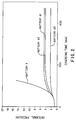
- FIG.2 is a graph showing a relationship between charging time and internal pressure in a battery of the present invention;
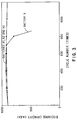
- FIG.3 is a graph showing a relationship between cycle numbers and a discharge capacity of the battery of the present invention;
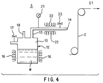
- FIG.4 is a schematic representation of a manufacturing method in accordance with the present invention;
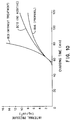
- FIGs.5-10 are graphs showing the relationship between the charging time and the internal pressure of a battery of the present invention;
- FIG.11 is an illustration of the hydrogen-absorbing alloy granules, a binder and a conductive substrate;
- FIG.12 is a cross-section of the hydrogen-absorbing alloy electrode;
- FIG.13 is a graph showing the relationship between each electrode and an oxygen gas consumption rate in accordance with the present invention;
- FIG.14 is a graph showing the relationship between each electrode and an activation intensity; and
- FIG.15 is a graph showing the relationship between the charging time and the internal pressure in a battery of the present invention.
- The following detailed description is of the best presently contemplated mode of carrying out the invention. This description is not to be taken in a limiting sense, but is made merely for the purpose of illustrating general principles and embodiments of the invention. The scope of the invention is defined by the appended claims.
- In accordance with a first experiment, small portions of a hydrogen-absorbing alloy electrode surface may be covered with remaining binder. However, a hydrogen-absorbing alloy readily reacts with oxygen gas generated from a positive electrode. As a result, the oxygen gas is consumed on the electrode surface, and such consumption facilitates a recombination between oxygen and hydrogen. Further, the electrode surface can freely contact an electrolyte. The negative electrode reaction is improved; thus, the cycle life of the negative electrode can be increased.
- FIG.1 is a cross-section of a cylindrical type metal hydride storage battery equipped with a hydrogen-absorbing alloy electrode of the present invention. In FIG.1, a
positive electrode 1 of the sintered type, a hydrogen-absorbing alloynegative electrode 2 according to the present invention and aseparator 3, which is disposed between thenegative electrode 2 and thepositive electrode 1, are wound spirally, and compose anelectrode body 4. Theelectrode body 4 is housed within anouter case 6 acting as a negative terminal. Thenegative electrode 2 is electrically connected to theouter case 6 by anegative lead 5. Theouter case 6 is sealed by acap 8 through an insulatingpacking 7. Thecap 8 is equipped with a safety valve. In thecap 8, acoil spring 9 is provided. When the internal pressure of the battery increases, thecoil spring 9 is pressed in the direction "A" and compressed and gas in the battery can be released through the safety valve. Thecap 8 is electrically connected to thepositive electrode 1 by apositive lead 10. - The above battery is made as follows. First, Mm (so-called "Misch metal", a mixture of rare-earth elements), nickel (Ni), cobalt (Co), manganese (Mn) and aluminum (Al) are measured and mixed in a ratio of 1:3.2:1:0.6:0.2. These constituents are melted in a high frequency furnace using argon atmosphere to obtain a melt and the melt is cooled, thereby producing a hydrogen-absorbing alloy bulk. The alloy is represented by the formula MmNi3.2CoMn0.6Al0.2. The hydrogen-absorbing alloy bulk is crushed and classified into granules of 50 µm average size. Next, the granules are kneaded into a paste with polyethyleneoxide (PEO) as a binder. The paste is coated onto both sides of a punched metal conductive substrate, thereby forming an electrode plate. The hydrogen-absorbing alloy granules are combined and covered with the binder so that the electrode plate surface has a thin film of binder. Then, the electrode plate is sprayed with steam. By this treatment, the binder of the surface is decomposed, and the binder is removed from the electrode plate surface. As a result, surface portions of the hydrogen-absorbing alloy granules on the electrode plate are exposed. The surface portions of the hydrogen-absorbing alloy granules may thereby be easily contacted by oxygen gas. The typical conditions of the steam spray are: a conductive substrate temperature is kept below 70 °C, and the spray steam volume is set under 1 cc/cm² of water. After spraying with the steam, the electrode plate is dried by far infrared heating, thereby producing the hydrogen-absorbing alloy
negative electrode 2. On drying, the conductive substrate temperature is kept below 70 °C, and the conductive substrate is moved at a speed ranging from 0.3m/min to 1.5m/min. - Finally, the
negative electrode 2 is combined with a sinteredtype nickel electrode 1 and aseparator 3 in order to form awound electrode body 4. Theelectrode body 4 is inserted into anouter case 6, and an alkaline electrolyte of 30 wt% KOH, is poured into theouter case 6. Then, theouter case 6 is sealed by the cap, whereby the metal hydride storage battery of cylindrical type is obtained. A battery comprising embodiment "A1" of the present invention is thus prepared. - The differences between the first embodiment 1-1 and a second embodiment 1-2 are explained below. Hydrogen-absorbing alloy granules, prepared in the same way as in the first embodiment 1-1, are mixed with a positive type photoresist as a binder to obtain a paste. The positive type photoresist is, for example, sold by Hoechst Celanese Corporation and composed of a mixture of novolac resin and O-quinone diazido. The viscosity of the paste ranges from about 100 cp to about 115 cp. The paste is coated onto both sides of the conductive substrate so as to provide an electrode plate. The electrode plate is dried at 85 °C for 15 minutes to remove the solvent from the binder. The electrode plate is exposed by a mercury-vapor lamp. Typical conditions are follows:
ultraviolet ranging from 325 µm to 450 µm, illuminance power ranging from 200 W/m² to 800 W/m² and exposing time ranging from 15 seconds to 60 seconds. After exposing, the electrode plate is developed in a developer of AZ-developer by dipping for 1 minute. - During the above treatments, the photoresist of the electrode surface is removed; however, the inner part of the photoresist of the electrode remains. During exposure, the photoresist of the electrode surface is irradiated by the ultraviolet; however, the inner part of the photoresist is not irradiated because of the hydrogen-absorbing alloy placed on the surface which acts as a photomask. Therefore, the inner part of the photoresist is retained, the hydrogen-absorbing alloy is held in the negative electrode, and is prevented from falling off during manufacturing.
- After developing, the electrode plate is rinsed with water, dried, and baked at 115 °C for 15 minutes. By this baking, adhesion between the hydrogen-absorbing granules and between the hydrogen-absorbing alloy granules and the conductive substrate improves. In this way, a negative electrode is prepared following which a battery of the second embodiment 1-2 is produced in the same way as the first embodiment 1-1. This embodiment is identified as battery "A2".
- The differences between the first embodiment 1-1 and a third embodiment 1-3 are explained below. Hydrogen-absorbing alloy granules, prepared in the same way as in the first embodiment 1-1, are mixed with a positive type photoresist as a binder to obtain a paste. The positive type photoresist is soluble in organic solvents. The viscosity of the paste ranges from about 100 cp to about 115 cp. The paste is coated onto both sides of the conductive substrate to obtain an electrode plate. The electrode plate is baked at 115 °C for 15 minutes to remove the binder solvent. The electrode plate, as a negative electrode, is wound with a positive electrode and a separator to form an electrode body of a spiral type. The electrode body is immersed in acetone to dissolve the binder and then dried. In this state, the 80% binder (photoresist) is removed. The binder is almost removed, the hydrogen-absorbing alloy granules are held by the positive electrode, the conductive substrate and also the separator. Therefore, in the negative electrode the hydrogen-absorbing alloy granules are prevented from falling off during manufacturing.
- After removing the binder, the electrode body is prepared, and inserted into an outer case thus forming a battery of the third embodiment 1-3. This battery may be called embodiment "A3" of the present invention.
- The differences between the first embodiment 1-1 and a comparative example are set forth below. The spraying steam treatment is not carried out in the comparative example, and then, an electrode plate is prepared and used as a negative electrode. A battery equipped with the negative electrode of the comparative example is produced in the same way as in the first embodiment 1-1. The battery of the comparative example is called "X". On the surface of the negative electrode, the binder remains; therefore, the surface is covered with a thin film of the binder.
-
- In TEST 1-1, the charging times and internal pressures of the batteries "A1", "A2", "A3" and "X" were determined. Typical test of the research are shown in FIG.2. The internal pressure of the battery is measured continuously by charging at 1 C rate. According to FIG.2, the batteries "A1", "A2" and "A3" prevent the internal pressure from increasing compared to the battery "X" of the comparative example. As to the capacity of oxygen consumption characteristics of the negative electrode, the battery "A3" is remarkably improved.
- In TEST 1-2, the cycle characteristics of the batteries "A1", "A2", "A3" and "X" were determined. Typical results of the test are shown in FIG.3. In FIG.3, the horizontal axis represents cycle times and the vertical axis represents discharge capacity of the battery. Typical conditions are set to charge at 1 C rate for 1.2 hours and to discharge at 2 C rate to 1.0 V battery voltage. According to FIG.3, the batteries "A1", "A2" and "A3" have excellent cycle characteristics as compared to the battery "X" of the comparative example.
- In the first embodiment 1-1, polyethylene oxide (PEO) is used as a water soluble binder, but polyvinyl alcohol (PVA), polyvinyl pyrrolidone (PVP) and polyvinyl butyral (PVB) may be used. Before the steam spraying treatment, an infrared-drying process for the paste can be used.
- In the second embodiment 1-2 and the third embodiment 1-3, positive type photoresists are used; a mixture of phenol resin and azido may also be used. Further, a negative type photoresist can also be used for the positive type photoresist.
- In the third embodiment 1-3, after preparing the
electrode body 4, by immersing theelectrode body 4 into acetone, the photoresist may be removed. And also, for a removing method of the photoresist, dry ashing method may be used. The dry ashing method uses RF plasma (13.56MHz); the photoresist is thereby decomposed into H₂O and CO₂. - As to the removing methods of the photoresist for the binder on a surface of the negative electrode, the method is not limited in the second embodiment 1-2. By using a roller impregnated with an organic solvent, the photoresist can be removed.
- In the third embodiment 1-3 acetone is used as the solvent, but solvents including ketone or cellosolveacetate may be used. The amount of the photoresist removed can be set, ranging from about 20 % to about 80 % of the initial amount of the photoresist. When the amount of photoresist is removed less than about 20 %, the advantages of the invention are not sufficiently obtained. The other hand, removing more than about 80% causes shedding off of the hydrogen-absorbing alloy granules. In order to control the amount of photoresist removal, the immerse on time of the electrode body in a solvent may be regulated.
- In a second experiment, after a thin film of a binder is formed on an electrode surface, the thin film is dissolved and removed by spraying with steam including an organic material. In this method, the organic material is added as a dissolution accelerant into the steam, and the thin film of the binder is quickly dissolved.
- As for the organic material, amines (ethylene diamine), ketones (acetone, methylethyl ketone), fatty acids (acetic acid), ethers (diethyl ether) and alcohols (ethanol, propanol, butanol) may be used. The organic materials can effectively dissolve the thin film of the binder by adding such materials to the steam, and various mixture of the organic materials may be used.
- The amount of the organic materials depends on the kind of binder. The kind of the organic materials and the thickness of the thin film depend upon the kind of binder, and the amount of the organic materials is set to range from about 0.1 parts weight to about 20 parts weight per 100 parts weight of water.
- As for a hydrogen-absorbing alloy, rare-earth hydrogen-absorbing alloy systems (LaNi₅, LaNi₃Co₂, partial replacement them, MmNi₅, MmNi₃Co₂), Ti-Ni hydrogen-absorbing alloy systems (Ti₂Ni, TiNi₂ and partial replacement of a part of nickel for cobalt, manganese or aluminum), Ti-Mn hydrogen-absorbing alloy systems, Ti-Fe hydrogen-absorbing alloy systems, Mg-Ni hydrogen-absorbing alloy systems, Ti-Zr hydrogen absorbing alloy systems and Zr-Mn hydrogen-absorbing alloy systems may be used.
- As for the binder of the present invention, resins with softening temperatures below 250°C may be used. For example, polyethylene oxide (PEO), polyvinyl pyrrolidone (PVP), polyvinyl alcohol (PVA), polyvinyl butyral (PVB) and hydroxypropyl cellulose (HPC) may be used.
- First, Mm (Misch metal), nickel (Ni), cobalt (Co), aluminum (Al) and manganese (Mn) are measured and mixed in a ratio of 1:3.2:1:0.6:0.2. They are melted in a high frequency furnace under an inert (argon) atmosphere, and cooled by a single roll process, then a hydrogen-absorbing alloy bulk is obtained. The hydrogen-absorbing alloy is represented by the formula MmNi3.2CoMn0.6Al0.2. The hydrogen-absorbing alloy bulk is crushed and classified into granules of 50 µm average size. Next, the granules are kneaded into a paste with polyethyleneoxide (PEO) as a binder at a 100:1 ratio. The paste is coated onto both sides of a punched nickel metal plate as a conductive substrate, and dried, whereby an electrode plate is formed. On the electrode plate, the hydrogen-absorbing alloy granules are combined and covered with the binder; the electrode plate surface has a thin film of a PEO binder. Then, the electrode plate is treated by spraying with steam including ethanol as an organic material. A ratio of water and the ethanol is set at 100 parts weight and 5 parts weight. The binder of the electrode surface is thereby decomposed, and the binder is removed form the electrode surface. As a result, hydrogen-absorbing alloy granules on the electrode surface are no longer covered by the binder and a part of the hydrogen-absorbing alloy granules can make easy contact with oxygen gas; an electrode identified a "E1" is thereby produced.
- FIG.4 is a process illustration of the present invention. A steam treatment system "S" has a
steam generating tank 12, a steam supplying pipe 13 and anozzle 14. Thesteam generating tank 12 includes steam treatment liquid "W" composed of a mixture of water and ethanol. Aspace 15 in thetank 12 comprises a steam generating space above the steam treatment liquid "W". In thesteam generating tank 12, side walls are equipped withheaters 16 facing a part of the steam treatment liquid "W". Theheaters 16 heat up the steam treatment liquid "W" to generate the steam. One of the side walls has asafety valve 17 for releasing excessive internal pressure. Along upper the margin of thesteam generating space 15, asupply pipe 18 and a steam supply pipe 13 are mounted. Thesupply pipe 18 supplies the steam treatment liquid "W" heated at about 60°C for thesteam generating tank 12. The steam supply pipe 13 produces the steam from thesteam generating space 15. A tapered portion of the steam supply pipe 13 forms anozzle 14. The steam supply pipe 13 has apressure gage 21,pre-heaters 22 for preventing condensation and apressure regulating valve 23. In the above steam treatment system "S", steam is generated by heating the steam treatment liquid "W" in thesteam generating tank 12; the steam is discharged from thenozzle 14. As a result, the steam impinges upon a surface of the electrode plate to form the electrode E1. Then, the binder on the surface of the electrode plate "E" is dissolved and removed. There is no limitation as to the shape of thenozzle 14. - In a second embodiment 2-2, a steam treatment liquid comprising a mixture of water (100 parts weight) and diethylether (5 parts weight) is used. Except for the steam treatment liquid, the conditions are the same as in the first embodiment 2-1. In the second embodiment 2-2, a treated electrode "E2" of the present invention is produced.
- In a third embodiment 2-3, a steam treatment liquid comprising a mixture of water (100 parts weight) and ethylene diamine (5 parts weight) is used. Except for the steam treatment liquid, the conditions are the same as in the first embodiment 2-1. In the third embodiment 2-3, a treated electrode "E3" of the present invention is produced.
- In a fourth embodiment 2-4, a steam treatment liquid comprising a mixture of water (100 parts weight) and methylethyl ketone (5 parts weight) is used. Except for the steam treatment liquid, the conditions are the same as in the first embodiment 2-1. In the fourth embodiment 2-4, a treated electrode "E4" of the present invention is produced.
- In a fifth embodiment 2-5, a steam treatment liquid comprising a mixture of water (100 parts weight) and acetic acid (5 parts weight) is used. Except the steam treatment liquid, the conditions are the same as in the first embodiment 2-1. In the fifth embodiment 2-5, a treated electrode "E5" of the present invention is produced.
- In a sixth embodiment 2-6, a steam treatment liquid comprising a mixture of water (100 parts weight) and propanol (5 parts weight) is used. Except the steam treatment liquid, the conditions are the same as in the first embodiment 2-1. In the sixth embodiment 2-6, a treated electrode "E6" of the present invention is produced.
- In each embodiment, non-treated electrodes (without the above-described steam spraying) including an organic material were prepared, and identified as "CE1", "CE2", "CE3", "CE4", "CE5" and "CE6", respectively. Further, in each embodiment, electrodes treated with water steam and without any organic mate rials (no additive) were prepared, and identified as "CE7", "CE8", "CE9", "CE10", "CE11" and "CE12", respectively.
- These electrodes, as negative electrodes, were combined with sintered type nickel hydroxide electrodes to obtain batteries of standard AA size. These batteries equipped with the electrode "E1- E6", "CE1-CE6" and "CE7-CE12" were prepared and identified as "BA1-BA6" of the present invention, and "BC1-BC6" and "BC7- BC12" of the comparative examples. These batteries included 30wt% KOH as an alkaline electrolyte and polyamide unwoven fabric as a separator.
- In TEST 2-1, the relationships between charging time and internal pressure for the batteries "BA1-BA6", "BC1-BC6" and "BC7-BC12" were determined. Typical results of the test are shown in FIGs.5-10, which show rapid charging characteristics of the batteries. The internal pressure of the battery was measured continuously by charging at a 1C rate.
- According to FIG.5 to FIG.10, the batteries "BC1-BC6" equipped with the electrodes "CE1-CE6" without treatment of steam rapidly increase the internal pressure of the batteries. The batteries "BA1-BA6" equipped with the electrodes "E1-E6" of the present invention which were treated by steam with an organic material hardly increase the internal pressure of the batteries and have superior oxygen consumption characteristics. On the other hand, the batteries "BC7-BC12" equipped with the electrodes "CE7-CE12" have superior oxygen consumption characteristics compared to the batteries "BC1-BC6". However, compared to the batteries BA1-BA6, the batteries BC7-BC12 are inferior in their consumption of oxygen gas, thus rapid increases of internal pressure are observed.
- In a third experiment, using a large size hydrogen-absorbing alloy granules and small size hydrogen-absorbing alloy granules with binder, thicknesses of a thin film of binder formed on an hydrogen-absorbing alloy granule are different depending upon the size. It is known that the thickness of the large size granules is thinner than that of the small size granules because of a difference caused by their surface tension curvatures. Using the above hydrogen-absorbing alloys for the negative electrode in an alkaline battery, the thin film is dissolved and removed by water included in an alkaline electrolyte; the hydrogen-absorbing alloy is thereby exposed. In the present invention, a part of the thin film is so thin that dilution and removal of the binder are facilitated. Therefore, the characteristics of the battery, namely, the oxygen gas consumption characteristics, are improved. The size of the hydrogen-absorbing alloy granule may be set ranging from a thickness of a layer of the hydrogen-absorbing paste to a half of the thickness.
- First, Mm (Misch metal), nickel (Ni), cobalt (Co), manganese (Mn) and aluminum (Al) are measured, mixed in a ratio of 1:3.2:1:0.6:0.2, and melted in a high frequency furnace under an inert (argon) atmosphere. The melt is cooled, and a hydrogen-absorbing alloy bulk is thereby obtained. The alloy is represented by the formula MmNi3.2CoMn0.6Al0.2. The hydrogen-absorbing alloy bulk is crushed and classified into granules less than 50 µm size (second granules) and about 100 µm size (first granules), thus two kinds of hydrogen-absorbing alloy granules are prepared. Next, after mixing less than 50 µm size granules and 100 µm size granules at a mixture ratio of 95:5, two kinds of granules are mixed and kneaded with polyethyleneoxide (PEO) as a water-soluble binder to obtain a paste. The paste is coated onto both sides of a punched nickel metal plate as a conductive substrate, and dried; an electrode plate is thereby produced. As shown in FIG.11, a thickness of a
binder film 113 on thelarge size granules 112 is thinner than that onsmall size granules 111. As to a range of the large size granules of the hydrogen-absorbing alloy shown in FIG.12, when a thickness of a layer composed of hydrogen-absorbing alloy granules is represented by "Y" and a diameter of the large size granules of the hydrogen-absorbing alloy is represented by "P". Thus, the relations between "Y" and "P" are represented by the equation Y/2<P<Y, which was obtained empirically. The hydrogen-absorbing alloy electrode so produced is identified as electrode "B1". - In a second embodiment 3-2, small granules of a diameter not more than 50 µm and large granules having an about 100 µm diameter are mixed at a weight ratio of 90:10, and a mixture is used. Except for the mixture, the conditions are the same as in the first embodiment. In the second embodiment 3-2, an electrode "B2" of the present invention is prepared.
- In a third embodiment 3-3, small granules of a diameter not more than 50 µm and large granules having an about 100 µm diameter are mixed at a weight ratio of 80:20, and a mixture is used. Except for the mixture, the conditions are the same as in the first embodiment 3-1. In the third embodiment 3-3, an electrode "B3" of the present invention is prepared.
- In a comparative example, as for the hydrogen-absorbing alloy granules, small granules of a diameter not more than 50 µm are used; the other condition are the same as in the first embodiment 3-1. In the comparative embodiment, an electrode "Y" is prepared.
- These electrodes "B1", "B2", "B3" and "Y", as negative electrodes, are combined with nickel electrodes to form hermetic single cells. These cells, equipped with the electrodes "B1", "B2", "B3" and "Y", are called "b1", "b2", "b3" of the present inventions and "y" of the comparative example. These cells include a separator impregnated with 30wt% KOH as an alkaline electrolyte.
- In TEST 3-1, the oxygen consumption rate of the cells of "b1", "b2", "b3" and "y" was measured. After charging each cell at 30 mA current for 10 hours to reach charging depth of 72%, oxygen gas filled the hermetic containers of the cells. The internal pressure of the hermetic containers was measured; thus, an oxygen consumption rate was calculated. In FIG.13, results are shown relatively compared to the comparative example represented by 100 rates. From the results in FIG.13, the electrodes "B1", "B2" and "B3" of the present invention have superior oxygen gas consumption characteristics.
- In TEST 3-2, the above electrodes "B1", "B2", "B3" and "Y" were combined with sintered type nickel hydroxide electrodes for a positive electrode to form batteries. These batteries, equipped with the electrodes "B1", "B2", "B3" and "Y", were designated "B1b", "B2b", "B3b" of the present inventions and "Yb" of the comparative example. These cells included a separator impregnated with 30wt% KOH as an alkaline electrolyte.
- In TEST 3-2, an initial activity of those electrodes "B1", "B2", "B3" and "Y" was measured. Typical conditions were set as follows. After charging a battery at a rate of 50mA/g for 8 hours, each battery was discharged at a rate of 50mA/g and at a rate of 200mA/g. In TEST 3-2, discharging at the rate of 50mA/g, a capacity is set C50 and discharging at the rate of 200mA/g a capacity is set C200, and a value of C50/C200X100(%) is calculated. When the value of C50/C200X100(%) becomes larger, the initial activity of the electrode becomes higher. In FIG.14, the vertical axis relatively represents a degree of the initial activity by the comparative electrode "Y" setting 100. According to FIG. 14, the electrodes "B1", "B2" and "B3" of the present invention have superior characteristics of the initial characteristics compared to the electrode "Y" of the comparative example.
- In TEST 3-3, the electrodes "B1", "B2", "B3" and "Y" for negative electrodes are combined with sintered type nickel hydroxide electrode for a positive electrode to obtain the battery shown in FIG.1. These batteries equipped with the electrode "B1", "B2", "B3" and "Y", are designated "b1", "b2", "b3" of the present inventions, and "y" of the comparative example. These batteries include a separator impregnated with 30wt% KOH as an alkaline electrolyte.
- In TEST 3-3, an internal pressure of the batteries "b1", "b2", "b3" and "y" is measured. Typical conditions were set as follows. After charging battery at a 1C rate continuously, each internal pressure of the battery is measured. According to FIG.15, the batteries "b1", "b2" and "b3" of the present invention have superior oxygen gas consumption characteristics com pared to the battery "y" of the comparative example, thus an increase of the internal pressure in the battery is prevented.
- Judging from above TEST 3-1, TEST 3-2 and TEST 3-3, an amount of the large size granules in the hydrogen-absorbing alloy may be preferred ranging from about 5 part weight to about 20 parts weight. The reason for this is based on the fact that use of too many of the large size granules causes reduction to fill up volume in a negative electrode, and cause decrease of real reaction area on the hydrogen-absorbing alloy granules.
- Low temperature characteristics, although not shown in this specification, are also improved by the conditions of the third experiment.
- As shown in the first and second experiments, the steam spraying treatment may be combined with the third experiment. As a result of this combination, the advantage of removing binder is improved.
- While the description above refers to particular embodiments of the present invention, it will be understood that many modifications may be made without departing from the spirit thereof. The accompany claims are intended to cover such modifications as would fall within the true scope and spirit of the present invention.
- The presently disclosed embodiments are therefore to be considered in all respects as illustrative and not restrictive, the scope of the invention being indicated by the appended claims, rather than the foregoing description, and all changes which come within the meaning and range of equivalency of the claims are therefore intended to be embraced therein.
Claims (22)
- A hydrogen-absorbing alloy electrode comprising:
a conductive substrate;
a layer of hydrogen-absorbing alloy granules disposed on said conductive substrate; and
a binder for binding said hydrogen-absorbing alloy granules together and to said conductive substrate;
wherein a part of said hydrogen-absorbing alloy granules is exposed on a surface of said layer. - A hydrogen-absorbing alloy electrode according to claim 1, wherein said layer has a predetermined thickness and said hydrogen-absorbing alloy granules includes large size granules having a maximum diameter larger than half the thickness of said layer but smaller than the thickness of said layer.
- A hydrogen-absorbing alloy electrode according to claim 1, wherein said hydrogen-absorbing alloy granules include first granules having a first average diameter and second granules having a second average diameter smaller than said first diameter, said first granules being 5 wt% or more but less than 20 wt% of the total weight of said hydrogen-absorbing alloy granules.
- A hydrogen-absorbing alloy electrode comprising:
a conductive substrate;
a layer of hydrogen-absorbing alloy granules disposed on said conductive substrate, said hydrogen-absorbing alloy granules including large size granules having a maximum diameter larger than half the thickness of said layer but smaller than the thickness of said layer, said hydrogen-absorbing alloy granules including 5 wt% or more but less than 20 wt% of said large size granules; and
a binder for binding said hydrogen-absorbing alloy granules together and to said conductive substrate, wherein a part of said hydrogen-absorbing alloy granules is exposed on a surface of said layer. - A method of manufacturing a hydrogen-absorbing alloy electrode comprising the steps of:
mixing hydrogen-absorbing alloy granules with a binder to form a layer;
coating said layer onto a conductive substrate to produce an electrode plate; and
removing a part of said binder from a surface of said electrode plate to expose a part of said hydrogen-absorbing alloy granules in said surface to an electrolyte. - A method of manufacturing a hydrogen-absorbing alloy electrode according to claim 5, wherein said layer has a predetermined thickness and said hydrogen-absorbing alloy granules includes large size granules having a maximum diameter larger than half the thickness of said layer but smaller than the thickness of said layer.
- A method of manufacturing a hydrogen-absorbing alloy electrode according to claim 5, wherein said binder includes an organic soluble material, and said binder adjacent to said surface is removed by an organic solvent.
- A method of manufacturing a hydrogen-absorbing alloy electrode according to claim 5, wherein said binder includes a water soluble material, and said binder adjacent to said surface is removed by water.
- A method of manufacturing a hydrogen-absorbing alloy electrode according to claim 8, wherein said water soluble material is selected from a group consisting of polyethylene oxide (PEO), polyvinyl pyrrolidone (PVP), polyvinyl alcohol (PVA), polyvinyl butyral (PVB) and hydroxypropyl cellulose (HPC).
- A method of manufacturing a hydrogen-absorbing alloy electrode according to claim 8, wherein said water includes an organic material for resolving said binder.
- A method of manufacturing a hydrogen-absorbing alloy electrode according to claim 10, wherein said organic material is selected from a group consisting of amine, ketone, fatty acid, ether and alcohol.
- A method of manufacturing a hydrogen-absorbing alloy electrode according to claim 10, wherein said water includes said organic material by an amount ranging 0.1 wt% to 20 wt%.
- A method of manufacturing a hydrogen-absorbing alloy electrode comprising the steps of:
mixing hydrogen-absorbing alloy granules with a binder to form a layer, said binder including one type photoresist;
coating said layer onto a conductive substrate to provide an electrode plate;
irradiating said electrode plate by ultraviolet radiation; and
removing a part of said binder from a surface of said electrode plate to expose a part of said hydrogen-absorbing alloy granules in said surface to an electrolyte. - A method of manufacturing a hydrogen-absorbing alloy electrode according to claim 13, wherein said layer has a predetermined thickness and said hydrogen-absorbing alloy granules includes large size granules having a maximum diameter larger than half the thickness of said layer but smaller than the thickness of said layer.
- A method of manufacturing a hydrogen-absorbing alloy electrode according to claim 13, wherein said binder is defined by one of a positive type photoresist and a negative type photoresist.
- A method of manufacturing a hydrogen-absorbing alloy electrode according to claim 13, wherein said binder includes 100% of said one type photoresist.
- A method of manufacturing a hydrogen-absorbing alloy electrode according to claim 13, wherein said step of removing is carried out by a dry ashing method.
- A method of manufacturing a hydrogen-absorbing alloy electrode according to claim 13, wherein said binder is removed by a developer for said one type photoresist.
- A method of manufacturing a hydrogen-absorbing alloy electrode according to claim 16, wherein an amount ranging from 20 wt% to 80 wt% of said one type photoresist remains in said layer after said removing step.
- A method of manufacturing a hydrogen-absorbing alloy electrode comprising the steps of:
mixing hydrogen-absorbing alloy granules with a binder selected from a group consisting of polyethylene oxide (PEO), polyvinyl pyrrolidone (PVP), polyvinyl alcohol (PVA), polyvinyl butyral (PVB) and hydroxypropyl cellulose (HPC) to obtain a layer;
coating said layer onto a conductive substrate to provide an electrode plate;
subjecting said electrode piate to water, said water including an organic material selected from a group consisting of amine, ketone, fatty acid, ether and alcohol; and
drying said electrode plate; wherein said hydrogen-absorbing alloy granules in said surface is exposed to an electrolyte. - A method of manufacturing a hydrogen-absorbing alloy electrode according to claim 20, wherein said layer has a predetermined thickness and said hydrogen-absorbing alloy granules includes large size granules having a maximum diameter larger than half the thickness of said layer but smaller than the thickness of said layer.
- A method of manufacturing a hydrogen-absorbing alloy electrode according to 20, wherein said water includes said organic material by an amount ranging from 0.1 wt% to 20 wt%.
Applications Claiming Priority (2)
| Application Number | Priority Date | Filing Date | Title |
|---|---|---|---|
| JP355881/92 | 1992-12-17 | ||
| JP4355881A JP2975790B2 (en) | 1992-12-17 | 1992-12-17 | Surface treatment method for hydrogen storage alloy electrode |
Publications (3)
| Publication Number | Publication Date |
|---|---|
| EP0602768A2 true EP0602768A2 (en) | 1994-06-22 |
| EP0602768A3 EP0602768A3 (en) | 1995-05-17 |
| EP0602768B1 EP0602768B1 (en) | 1998-09-16 |
Family
ID=18446212
Family Applications (1)
| Application Number | Title | Priority Date | Filing Date |
|---|---|---|---|
| EP93305538A Expired - Lifetime EP0602768B1 (en) | 1992-12-17 | 1993-07-14 | Hydrogen-absorbing alloy electrode and manufacturing method therefor |
Country Status (3)
| Country | Link |
|---|---|
| EP (1) | EP0602768B1 (en) |
| JP (1) | JP2975790B2 (en) |
| DE (1) | DE69321084T2 (en) |
Cited By (3)
| Publication number | Priority date | Publication date | Assignee | Title |
|---|---|---|---|---|
| EP0697745A1 (en) * | 1994-07-22 | 1996-02-21 | Sanyo Electric Co., Ltd. | Hydrogen-absorbing alloy electrode for metal hydride alkaline battery |
| FR2733355A1 (en) * | 1995-04-24 | 1996-10-25 | Accumulateurs Fixes | NEGATIVE ELECTRODE OF ALKALINE BATTERY |
| EP0961332A1 (en) * | 1998-05-19 | 1999-12-01 | Sanyo Electric Co., Ltd. | Hydrogen storage alloy electrode and method for fabrication thereof |
Families Citing this family (3)
| Publication number | Priority date | Publication date | Assignee | Title |
|---|---|---|---|---|
| US5629000A (en) * | 1994-11-25 | 1997-05-13 | Sanyo Electric Co., Ltd. | Hydrogen-absorbing alloy electrode for metal hydride alkaline batteries and process for producing the same |
| JPH09180715A (en) * | 1995-12-21 | 1997-07-11 | Toyota Central Res & Dev Lab Inc | Surface treatment method of hydrogen storage alloy with steam and the obtained alloy |
| DE102019102557A1 (en) * | 2019-02-01 | 2020-08-06 | Volkswagen Aktiengesellschaft | Method of making an electrode |
Family Cites Families (6)
| Publication number | Priority date | Publication date | Assignee | Title |
|---|---|---|---|---|
| IT974430B (en) * | 1972-01-08 | 1974-06-20 | Deutsche Automobilgesellsch | PROCEDURE FOR THE MANUFACTURE OF HYDROGEN STORAGE ELECTRODES FOR ELECTRIC ACCUMULATORS |
| JPS63138653A (en) * | 1986-11-28 | 1988-06-10 | Hitachi Metals Ltd | Alkaline secondary battery |
| US5034289A (en) * | 1989-02-23 | 1991-07-23 | Matsushita Electric Industrial Co., Ltd. | Alkaline storage battery and method of producing negative electrode thereof |
| JP3177653B2 (en) * | 1989-03-08 | 2001-06-18 | 日本電池株式会社 | Method for producing hydrogen storage electrode |
| DE69014185T2 (en) * | 1989-09-18 | 1995-03-30 | Toshiba Battery | Secondary nickel metal hydride cell. |
| JP2980328B2 (en) * | 1989-09-29 | 1999-11-22 | 株式会社東芝 | Hydrogen storage alloy for battery, method for producing the same, and nickel-metal hydride secondary battery |
-
1992
- 1992-12-17 JP JP4355881A patent/JP2975790B2/en not_active Expired - Fee Related
-
1993
- 1993-07-14 EP EP93305538A patent/EP0602768B1/en not_active Expired - Lifetime
- 1993-07-14 DE DE69321084T patent/DE69321084T2/en not_active Expired - Fee Related
Cited By (7)
| Publication number | Priority date | Publication date | Assignee | Title |
|---|---|---|---|---|
| EP0697745A1 (en) * | 1994-07-22 | 1996-02-21 | Sanyo Electric Co., Ltd. | Hydrogen-absorbing alloy electrode for metal hydride alkaline battery |
| US5616435A (en) * | 1994-07-22 | 1997-04-01 | Sanyo Electric Co., Ltd. | Hydrogen-absorbing alloy electrode for metal hydride alkaline battery |
| CN1084934C (en) * | 1994-07-22 | 2002-05-15 | 三洋电机株式会社 | Hydrogen-absorbing alloy electrode for metal hydride alkaline battery |
| FR2733355A1 (en) * | 1995-04-24 | 1996-10-25 | Accumulateurs Fixes | NEGATIVE ELECTRODE OF ALKALINE BATTERY |
| EP0740355A1 (en) * | 1995-04-24 | 1996-10-30 | Saft | Negative electrode for Ni-metal hydride accumulator |
| EP0961332A1 (en) * | 1998-05-19 | 1999-12-01 | Sanyo Electric Co., Ltd. | Hydrogen storage alloy electrode and method for fabrication thereof |
| US6258482B1 (en) | 1998-05-19 | 2001-07-10 | Sanyo Electric Co., Ltd. | Hydrogen storage alloy electrode and method for fabrication thereof |
Also Published As
| Publication number | Publication date |
|---|---|
| DE69321084T2 (en) | 1999-02-25 |
| EP0602768B1 (en) | 1998-09-16 |
| JP2975790B2 (en) | 1999-11-10 |
| DE69321084D1 (en) | 1998-10-22 |
| JPH06187980A (en) | 1994-07-08 |
| EP0602768A3 (en) | 1995-05-17 |
Similar Documents
| Publication | Publication Date | Title |
|---|---|---|
| US6495289B1 (en) | Lithium secondary cell with an alloyed metallic powder containing electrode | |
| KR100312945B1 (en) | Mg-based negative electrode active material, method of manufacturing the same, hydrogen-storage alloy electrode, and alkali secondary battery | |
| KR920007381B1 (en) | Making method of akaline battery | |
| EP0647973B1 (en) | Hydrogen-absorbing alloy electrode and process for producing the same | |
| US4994334A (en) | Sealed alkaline storage battery and method of producing negative electrode thereof | |
| JP3214341B2 (en) | Manufacturing method of hydrogen storage alloy for batteries | |
| CN1117207A (en) | Nickel-hydrogen secondary battery and method for manufacturing the same | |
| EP0602768B1 (en) | Hydrogen-absorbing alloy electrode and manufacturing method therefor | |
| CN101320805A (en) | Nickel-hydrogen battery and preparation method for anode material | |
| US5395403A (en) | Hydrogen-absorbing alloy electrode and manufacturing method therefor | |
| Kaiya et al. | Improvement in cycle life performance of high capacity nickel-metal hydride battery | |
| CN101027802A (en) | Hydrogen storage electrodes and nickel metal hydride batteries | |
| CN100359722C (en) | Sealed nickel metal hydride storage battery and manufacturing method thereof | |
| JP3515286B2 (en) | Electrodes for secondary batteries | |
| JP2875822B2 (en) | Method for manufacturing nickel-hydrogen secondary battery | |
| JPH08264174A (en) | Hydrogen storage alloy cathode and manufacturing method thereof | |
| JP3093801B2 (en) | Battery manufacturing method and battery | |
| JP3012658B2 (en) | Nickel hydride rechargeable battery | |
| JP3459472B2 (en) | Hydrogen storage alloy electrode for sealed alkaline storage battery and method for producing the same | |
| JP2001266860A (en) | Nickel hydrogen storage battery | |
| JP3267156B2 (en) | Nickel hydride rechargeable battery | |
| JPH0799690B2 (en) | Method for manufacturing hydrogen storage electrode | |
| JPS58201271A (en) | Sealed type alkaline storage battery | |
| JPH103940A (en) | Nickel-metal hydride storage battery and its manufacture | |
| JP3136961B2 (en) | Method of treating hydrogen storage alloy for batteries |
Legal Events
| Date | Code | Title | Description |
|---|---|---|---|
| PUAI | Public reference made under article 153(3) epc to a published international application that has entered the european phase |
Free format text: ORIGINAL CODE: 0009012 |
|
| AK | Designated contracting states |
Kind code of ref document: A2 Designated state(s): DE FR |
|
| PUAL | Search report despatched |
Free format text: ORIGINAL CODE: 0009013 |
|
| AK | Designated contracting states |
Kind code of ref document: A3 Designated state(s): DE FR |
|
| 17P | Request for examination filed |
Effective date: 19950731 |
|
| 17Q | First examination report despatched |
Effective date: 19960321 |
|
| GRAG | Despatch of communication of intention to grant |
Free format text: ORIGINAL CODE: EPIDOS AGRA |
|
| GRAG | Despatch of communication of intention to grant |
Free format text: ORIGINAL CODE: EPIDOS AGRA |
|
| GRAH | Despatch of communication of intention to grant a patent |
Free format text: ORIGINAL CODE: EPIDOS IGRA |
|
| GRAH | Despatch of communication of intention to grant a patent |
Free format text: ORIGINAL CODE: EPIDOS IGRA |
|
| GRAA | (expected) grant |
Free format text: ORIGINAL CODE: 0009210 |
|
| AK | Designated contracting states |
Kind code of ref document: B1 Designated state(s): DE FR |
|
| REF | Corresponds to: |
Ref document number: 69321084 Country of ref document: DE Date of ref document: 19981022 |
|
| ET | Fr: translation filed | ||
| K2C3 | Correction of patent specification (complete document) published |
Effective date: 19980916 |
|
| PLBE | No opposition filed within time limit |
Free format text: ORIGINAL CODE: 0009261 |
|
| STAA | Information on the status of an ep patent application or granted ep patent |
Free format text: STATUS: NO OPPOSITION FILED WITHIN TIME LIMIT |
|
| 26N | No opposition filed | ||
| PGFP | Annual fee paid to national office [announced via postgrant information from national office to epo] |
Ref country code: DE Payment date: 20070712 Year of fee payment: 15 |
|
| PGFP | Annual fee paid to national office [announced via postgrant information from national office to epo] |
Ref country code: FR Payment date: 20070710 Year of fee payment: 15 |
|
| PG25 | Lapsed in a contracting state [announced via postgrant information from national office to epo] |
Ref country code: DE Free format text: LAPSE BECAUSE OF NON-PAYMENT OF DUE FEES Effective date: 20090203 |
|
| REG | Reference to a national code |
Ref country code: FR Ref legal event code: ST Effective date: 20090331 |
|
| PG25 | Lapsed in a contracting state [announced via postgrant information from national office to epo] |
Ref country code: FR Free format text: LAPSE BECAUSE OF NON-PAYMENT OF DUE FEES Effective date: 20080731 |