EP0602817A2 - Dispositif de traitement d'un signal vidéo numérique - Google Patents
Dispositif de traitement d'un signal vidéo numérique Download PDFInfo
- Publication number
- EP0602817A2 EP0602817A2 EP93309515A EP93309515A EP0602817A2 EP 0602817 A2 EP0602817 A2 EP 0602817A2 EP 93309515 A EP93309515 A EP 93309515A EP 93309515 A EP93309515 A EP 93309515A EP 0602817 A2 EP0602817 A2 EP 0602817A2
- Authority
- EP
- European Patent Office
- Prior art keywords
- error
- blocks
- record
- concealment
- video signal
- Prior art date
- Legal status (The legal status is an assumption and is not a legal conclusion. Google has not performed a legal analysis and makes no representation as to the accuracy of the status listed.)
- Granted
Links
Images



Classifications
-
- G—PHYSICS
- G11—INFORMATION STORAGE
- G11B—INFORMATION STORAGE BASED ON RELATIVE MOVEMENT BETWEEN RECORD CARRIER AND TRANSDUCER
- G11B20/00—Signal processing not specific to the method of recording or reproducing; Circuits therefor
- G11B20/10—Digital recording or reproducing
- G11B20/18—Error detection or correction; Testing, e.g. of drop-outs
-
- H—ELECTRICITY
- H04—ELECTRIC COMMUNICATION TECHNIQUE
- H04N—PICTORIAL COMMUNICATION, e.g. TELEVISION
- H04N21/00—Selective content distribution, e.g. interactive television or video on demand [VOD]
- H04N21/20—Servers specifically adapted for the distribution of content, e.g. VOD servers; Operations thereof
- H04N21/23—Processing of content or additional data; Elementary server operations; Server middleware
- H04N21/236—Assembling of a multiplex stream, e.g. transport stream, by combining a video stream with other content or additional data, e.g. inserting a URL [Uniform Resource Locator] into a video stream, multiplexing software data into a video stream; Remultiplexing of multiplex streams; Insertion of stuffing bits into the multiplex stream, e.g. to obtain a constant bit-rate; Assembling of a packetised elementary stream
-
- H—ELECTRICITY
- H04—ELECTRIC COMMUNICATION TECHNIQUE
- H04N—PICTORIAL COMMUNICATION, e.g. TELEVISION
- H04N19/00—Methods or arrangements for coding, decoding, compressing or decompressing digital video signals
- H04N19/10—Methods or arrangements for coding, decoding, compressing or decompressing digital video signals using adaptive coding
- H04N19/102—Methods or arrangements for coding, decoding, compressing or decompressing digital video signals using adaptive coding characterised by the element, parameter or selection affected or controlled by the adaptive coding
- H04N19/124—Quantisation
- H04N19/126—Details of normalisation or weighting functions, e.g. normalisation matrices or variable uniform quantisers
-
- H—ELECTRICITY
- H04—ELECTRIC COMMUNICATION TECHNIQUE
- H04N—PICTORIAL COMMUNICATION, e.g. TELEVISION
- H04N19/00—Methods or arrangements for coding, decoding, compressing or decompressing digital video signals
- H04N19/85—Methods or arrangements for coding, decoding, compressing or decompressing digital video signals using pre-processing or post-processing specially adapted for video compression
- H04N19/89—Methods or arrangements for coding, decoding, compressing or decompressing digital video signals using pre-processing or post-processing specially adapted for video compression involving methods or arrangements for detection of transmission errors at the decoder
- H04N19/895—Methods or arrangements for coding, decoding, compressing or decompressing digital video signals using pre-processing or post-processing specially adapted for video compression involving methods or arrangements for detection of transmission errors at the decoder in combination with error concealment
-
- H—ELECTRICITY
- H04—ELECTRIC COMMUNICATION TECHNIQUE
- H04N—PICTORIAL COMMUNICATION, e.g. TELEVISION
- H04N21/00—Selective content distribution, e.g. interactive television or video on demand [VOD]
- H04N21/40—Client devices specifically adapted for the reception of or interaction with content, e.g. set-top-box [STB]; Operations thereof
- H04N21/43—Processing of content or additional data, e.g. demultiplexing additional data from a digital video stream; Elementary client operations, e.g. monitoring of home network or synchronising decoder's clock; Client middleware
- H04N21/434—Disassembling of a multiplex stream, e.g. demultiplexing audio and video streams, extraction of additional data from a video stream; Remultiplexing of multiplex streams; Extraction or processing of SI; Disassembling of packetised elementary stream
-
- H—ELECTRICITY
- H04—ELECTRIC COMMUNICATION TECHNIQUE
- H04N—PICTORIAL COMMUNICATION, e.g. TELEVISION
- H04N9/00—Details of colour television systems
- H04N9/79—Processing of colour television signals in connection with recording
- H04N9/80—Transformation of the television signal for recording, e.g. modulation, frequency changing; Inverse transformation for playback
- H04N9/804—Transformation of the television signal for recording, e.g. modulation, frequency changing; Inverse transformation for playback involving pulse code modulation of the colour picture signal components
- H04N9/8042—Transformation of the television signal for recording, e.g. modulation, frequency changing; Inverse transformation for playback involving pulse code modulation of the colour picture signal components involving data reduction
- H04N9/8047—Transformation of the television signal for recording, e.g. modulation, frequency changing; Inverse transformation for playback involving pulse code modulation of the colour picture signal components involving data reduction using transform coding
-
- H—ELECTRICITY
- H04—ELECTRIC COMMUNICATION TECHNIQUE
- H04N—PICTORIAL COMMUNICATION, e.g. TELEVISION
- H04N9/00—Details of colour television systems
- H04N9/79—Processing of colour television signals in connection with recording
- H04N9/87—Regeneration of colour television signals
- H04N9/88—Signal drop-out compensation
- H04N9/888—Signal drop-out compensation for signals recorded by pulse code modulation
-
- H—ELECTRICITY
- H04—ELECTRIC COMMUNICATION TECHNIQUE
- H04N—PICTORIAL COMMUNICATION, e.g. TELEVISION
- H04N19/00—Methods or arrangements for coding, decoding, compressing or decompressing digital video signals
- H04N19/10—Methods or arrangements for coding, decoding, compressing or decompressing digital video signals using adaptive coding
- H04N19/102—Methods or arrangements for coding, decoding, compressing or decompressing digital video signals using adaptive coding characterised by the element, parameter or selection affected or controlled by the adaptive coding
- H04N19/124—Quantisation
-
- H—ELECTRICITY
- H04—ELECTRIC COMMUNICATION TECHNIQUE
- H04N—PICTORIAL COMMUNICATION, e.g. TELEVISION
- H04N19/00—Methods or arrangements for coding, decoding, compressing or decompressing digital video signals
- H04N19/60—Methods or arrangements for coding, decoding, compressing or decompressing digital video signals using transform coding
Definitions
- This invention relates to a digital video signal recording/reproducing apparatus using bit rate reduction coding and having a function of outputting reproduced data in a form of bit rate reduction coded state.
- an input video signal is converted into a digital signal by an A/D converter and compressed into a predetermined quantity of data by a bit rate reduction encoder.
- a method of bit rate reduction encoding the video signal a method of using orthogonal transformation is generally employed from the viewpoint of compression efficiency.
- the orthogonal transformation divides plural pixels into blocks and converts the pixels into frequency regions on a block by block basis.
- the data can be efficiently compressed. In this case, if the unit for the variable length encoding is increased, the efficiency of encoding can be improved. On the other hand, if an error is generated, the range of error propagation becomes large.
- an error correction parity is added, and then a sync signal and identification data (ID) are added to form a recording block (hereinafter called a sync block).
- a sync block is modulated for recording and recorded on a recording tape.
- the sync block is essentially composed of a sync signal for detecting the sync block from the reproduced signal, an identification data (ID) containing a track number for correctly writing the reproduced sync block into a memory and a sync block number, bit rate reduction encoded data of the video signal, and the error correction parity.
- the sync blocks thus composed are recorded on a track on the tape.
- a reproduced signal from a reproducing head is subjected to detection and demodulation of the sync block, and subjected to error correction in an error correction decoder according to the error correction parity added during recording.
- Error correction is effected to a certain number of errors by this process. However, if a drop out occurred, for example, due to a damage on a tape, such an error occurs that cannot be corrected by the error correction decoder. If an uncorrectable error occurred as such, error concealment is performed so that the influence of the error can be as inconspicuous as possible visually. The influence of the error propagates to the range within which a variable length encoding is completed.
- error concealment is carried out by substituting an entire sync block forming a compression block containing erroneous data with a previous corresponding sync block.
- the concealed data is decoded to the original data in a bit rate reduction decoder and converted through a D/A converter into the analog signal.
- a digital recording VTR using the bit rate reduction coding technology as shown above is disclosed, for example, in "An Experimental Study on a Home-Use Digital VTR" by C. Yamamitsu et al., IEEE Transaction on Consumer Electronics, Vol. 35, No. 3, August 1989, pp.450 - 457.
- the digital recording data sequence of 0 and 1 is recorded. If 0 and 1 are detected erroneously due to distortion of the reproduced waveform, it becomes an error of the data. In this case, if the error rate is a predetermined value or less, the error can be corrected by the error correction technique. Therefore, by setting the correctability adequately with respect to the error rate of the reproduced data, perfectly correct data can be reproduced. As a result, contrary to the analog recording in which repetition of dubbing results in an increase and accumulation of distortion, the digital recording is largely advantageous in that deterioration due to dubbing can be largely reduced.
- the "dubbing" means that a signal reproduced from one reproducing apparatus is sent to and recorded by another recording apparatus. Particularly, in the digital dubbing through no analog processing, deterioration of the signal can be further largely reduced.
- the orthogonal transform encoding is used as a method of bit rate reduction encoding of a video signal
- the orthogonal transformation and inverse orthogonal transformation are actually processed in a finite word length, so that the repetition of the orthogonal and inverse orthogonal transformations results in an accumulation of operational errors, leading to an increase in distortion.
- filtering processes such as the decimation, interpolation and the like are additionally carried out, the repetition of such filtering processes results in an increase in distortion as well.
- the method disclosed therein is such that concealed data are outputted for dubbing in any case. As a result, it cannot respond to any case that error concealment is not carried out in the bit rate reduction encoded state. Also, even in case that the concealment is to be carried out, it must be done in the form that the decoding is correctly carried out in the bit rate reduction decoder.
- An object of this invention is to provide an apparatus for processing digital video signals subjected to bit rate reduction coding, which is capable of restraining deterioration of data due to digital dubbing and correctly decoding the data after dubbing thereby to reproduce a high quality picture.
- the present invention provides a digital video signal processing apparatus for reproducing a digital video signal from bit rate reduction coded data recorded on a recording medium in the form of record blocks which have been produced by dividing a digital video signal into small blocks, forming macro blocks each being composed of a specified number of small blocks, bit rate reduction encoding each of the macro blocks, forming record blocks from the encoded macro blocks, respectively, and recording the record blocks on the recording medium, wherein each reproduced record block of bit rate reduction encoded data is multiplexed with a concealment information data concerning an error concealment of the record block.
- the reproduced record block may further be multiplexed with a decoding information data concerning a decoding of the record block or an error flag indicating an existence or absence of an error in the record block.
- the concealment information data, decoding information data and error flag may be included in a single status information.
- a digital video signal processing apparatus comprises: reproducing means for reproducing the record blocks from the recording medium; error correction means coupled to the reproducing means for correcting errors contained in the reproduced record blocks; error concealment means coupled to the error correction means for performing error concealment of each record block having an error which cannot be corrected by the error correction means; multiplexing means coupled to the error concealment means for multiplexing each record block with a concealment information data concerning the error concealment; first output means coupled to the multiplexing means for outputting the record blocks each being multiplexed with the concealment information data; decoding means coupled to the multiplexing means for decoding bit rate reduction encoded data in each of the record blocks to obtain a decoded digital video signal; and second output means coupled to the decoding means for outputting the decoded digital video signal.
- the multiplexing means may further multiplexes each record block which has been concealed by the error concealment means with a decoding information data concerning decoding of the record block, and each record block which has not been concealed by the error concealment means with an error flag indicating whether or not an error exists in the record block.
- the decoding means decodes the bit rate reduction encoded data of each record block according to the decoding information data multiplexed to the record block, and the first output means outputs the record blocks each being multiplexed with not only the concealment information data but also either the decoding information data or the error flag.
- the multiplexing means may express the concealment information data, the decoding information data and the error flag by a single coded data and multiplexes the single coded data as a status information data.
- a digital video signal processing apparatus comprises: reproducing means for reproducing the record blocks from the recording medium; error correction means coupled to the reproducing means for correcting errors contained in the reproduced record blocks; multiplexing means coupled to the error correction means for multiplexing each record block with a concealment information data concerning an error concealment and a first error flag indicating whether or not an error exists in the record block; first output means coupled to the multiplexing means for outputting the record blocks each being multiplexed with the concealment information data and the first error flag; decoding means coupled to the multiplexing means for decoding bit rate reduction encoded data in each of the record blocks according to the first error flag multiplexed to each record block to obtain a decoded digital video signal and for outputting a second error flag for each small block or each macro block of the decoded digital video signal; error concealment means for performing an error concealment of each small block or macro block having an error and contained in the decoded digital video signal according to the second error flag; and second output means coupled to the error concealing
- the digital video signal processing apparatus using bit rate reduction coding of this invention selects the information to be multiplexed to each reproduced record block depending on the reproducing process.
- a concealment information data indicating that an error concealment has been carried out is multiplexed to the record block.
- continuity of the bit rate reduction encoded data may be broken by concealing a part of the record blocks, information concerning decoding becomes necessary. So, a decoding information data indicating a decoding method of bit rate reduction encoded data is also multiplexed.
- an error flag is multiplexed to the corresponding record block to be outputted.
- the apparatus of this invention is capable of restraining deterioration of data due to digital dubbing and correctly processing the data after dubbing thereby to reproduce a high quality picture.
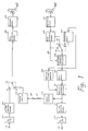
- Fig. 1 is a block diagram of a digital video signal processing apparatus according to a first embodiment of this invention.
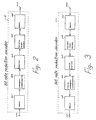
- Fig. 2 is a block diagram showing a detailed structure of the bit rate reduction encoder 118 shown in Fig. 1.
- Fig. 3 is a block diagram showing a detailed structure of the bit rate reduction decoder 111 shown in Fig. 1.
- Fig. 4 is an explanatory diagram of a method of reading out a compression block.
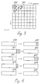
- Fig. 5 is a diagram for explaining the order of variable length encoding coefficients obtained by orthogonal transformation.
- Fig. 6 is an explanatory diagram of a method of inserting variable length encoded data into five UNITs.
- Fig. 7 is a diagram for explaining a UNIT structure multiplexed with a concealment information data and an additional information data.
- Fig. 8(a) is a diagram for explaining a concealment information data and an additional information data to be set when one UNIT of one compression block is erroneous.
- Fig. 8(b) is a diagram of explaining a concealment information data and an additional information data to be set when all UNITs of one compression block are erroneous.
- Fig. 9 is a block diagram of a digital video signal processing apparatus according to a second embodiment of this invention.
- Fig. 10 is a block diagram of a digital video signal processing apparatus according to a third embodiment of this invention.
- Fig. 11 is a diagram for explaining a UNIT structure multiplexed with a STATUS information data when the STATUS information data is defined as shown in Table 2.
- Fig. 12(a) is a diagram for explaining a STATUS information data to be set when the STATUS information data is defined as shown in Table 2 and one UNIT of one compression block is erroneous.
- Fig. 12(b) is a diagram for explaining a STATUS information data to be set when the STATUS information data is defined as shown in Table 2 and all UNITs of one compression blocks are erroneous.
- bit rate reduction encoded data are recorded on a recording medium (a magnetic tape in the embodiments) in the form of record blocks each composed of a sync signal, an identification data (ID) and a UNIT which is composed of a head area and encoded data as shown in Figs. 7 and 11.
- Fig 1. is a block diagram of a digital video signal processing apparatus according to a first embodiment of this invention.
- This apparatus comprises, on the reproduction side thereof, a reproducing head 100, a reproduction processing circuit 101 which amplifies, detects and demodulates data reproduced through the reproducing head 100 from a magnetic tape MT, an error correction decoder 102 which produces an error correction decoded data 103 and a flag 104 showing existence of an error on a UNIT by UNIT basis, a concealment memory 105, a switch 106 for selecting the output data 103 of the error correction decoder 102 and an output data of the concealment memory 105 on a UNIT by UNIT basis, a concealment information multiplexer 107 for multiplexing a data showing such information that an error concealment has been carried out (hereinafter called concealment information data) to the concealed UNIT, a delay memory 108 for delaying data for five UNITs, an additional information generator 109 which detects the concealment information data multiplexed to each UNIT to generate
- the apparatus comprises, on the recording side thereof, an input terminal 116 of an analog video signal, an A/D converter 117 for converting the analog video signal into a digital signal, a bit rate reduction encoder 118, an input terminal 119 for receiving the digital data outputted from the output terminal 115, a digital interface circuit 120 for converting the digital data in the transmission format sent from the terminal 119 into the original bit rate reduction encoded digital data, a switch 121 for selecting an output data of the bit rate reduction encoder 119 and an output data of the digital interface circuit 120, an error correction encoder 122, a recording processing circuit 123 for effecting modulation for recording, and a recording head 124 for recording the modulated data on a magnetic tape MT.
- the operation of the apparatus constituted as above will be explained below.
- Fig. 2 is a block diagram of the bit rate reduction encoder 118 shown in Fig. 1.
- the encoder 118 comprises an input terminal 200 of a video digital signal from the A/D converter 117, a memory 201 for dividing the digital video signal into small blocks each composed of horizontal 8 pixels x vertical 8 pixels, an orthogonal transformation circuit 202 for performing two-dimensional orthogonal transformation of data in each small blocks of 8 x 8 pixels, a quantizer 203, a variable length encoder 204, a memory 205 for inserting variable length encoded data into UNITs, and 206 is an output terminal of the data inserted into UNITs.
- Fig. 3 is a block diagram of the bit rate reduction decoder 111 shown in Fig. 1.
- the decoder 111 comprises an input terminal 300 of the data inserted into UNITs, a memory 301 for re-arranging the variable length encoded data inserted into UNITs in the order to be decoded, a variable length decoder 302, an inverse quantizer 303, an inverse orthogonal transformation circuit 304, a memory 305 for rearranging data on a block by block basis in the original order, and an output terminal 306 of the decoded data thus re-arranged in the original order.
- digital video signals received through the terminal 200 are written successively into the memory 201.
- the memory 201 In the memory 201, one frame is formed of two fields and the data is read out in the form of small blocks each composed of 8 x 8 pixels.
- the bit rate reduction encoding is carried out so that the quantity of data after variable length encoding is always kept constant in a unit of 30 small blocks. Therefore, the data is read out from the memory 201 in a unit of a compression block consisting of 30 small blocks.
- Fig. 4 is a diagram showing a method of reading out the compression block from the memory 201, in which one frame 400 forming one picture is divided into five regions.
- the input video signal is a 4:2:2 component signal, in which the chrominance signal has been decimated by one for every two lines. Accordingly, four luminance signal blocks and each of two chrominance signal blocks have the same position and area on a picture.
- a set of the four luminance signal blocks and two chrominance signal blocks is called a macro block.
- One compression block is composed of five macro blocks 401, 402, 403, 404 and 405.
- Fig. 5 is a diagram showing the order of variable-length encoding the coefficients obtained by the orthogonal transformation in the orthogonal transformation circuit 202 in the unit of the block of 8 x 8 pixels, in which a shaded are 500 shows the DC component and an area 501 shows AC components. As shown in Fig. 5, the coefficients are encoded by zigzag scan successively from the DC component, lower frequency AC components to higher frequency AC components.
- the quantizer 203 quantizes the data so that the quantity of data after variable length encoding is always kept constant in the compression block unit.
- the variable length encoded data in each compression block are written successively from the lower to higher frequency components into the memory 205.
- the variable length encoded data of the five macro blocks forming one compression block is divided and inserted into five UNITs.
- Fig. 6 is a diagram showing a method of inserting the variable length encoded data of five macro blocks by the memory 205 into five UNITs.
- the data 600, 601, 602, 603 and 604 are respectively obtained by encoding the five micro blocks.
- the data of each macro block are inserted into a corresponding one of UNITs 605, 606, 607, 608 and 609 successively from the first data.
- the quantity of data of each of the five macro blocks is not constant, there may occur such a case that the quantity of encoded data of one macro block becomes larger or smaller than the quantity of data insertable into the corresponding UNIT.
- one macro block corresponds to one UNIT, so that if one UNIT can be reproduced, the corresponding macro block can be reproduced on a picture.
- the data inserted into any other UNIT because of an excess of the data quantity corresponds to the high frequency components of a macro block, so that even if such data are lost, large deterioration in picture quality does not occur.
- the data in the compression block inserted into UNITs are rearranged in the memory 301 in the order to be variable length decoded, and applied with the inverse processes to the encoding processes through the variable length decoder 302, the inverse quantizer 303, inverse orthogonal transformation circuit 304 and memory 305.
- the data reproduced from the reproducing head 100 is detected and decoded in the reproduction processing circuit 101, and sent to the error correction decoder 102.
- the error correction is carried out in accordance with the error correction parity added in the recording processing.
- the error correction decoded data 103 is sent out from the error correction decoder 102 together with the flag 104.
- the flag 104 is sent to each UNIT, and set to "0" if the UNIT has no error and "1" if the UNIT has an error.
- the error concealment uses the concealment memory 105 and the switch 106.
- the switch 106 is switched on a UNIT by UNIT basis in response to the flag 104.
- the switch 106 is set to the A-side thereof.
- the data 103 read out from the error correction decoder 102 is selected and sent to the concealment information multiplexer 107 to be multiplexed with the concealment information data, and written into the delay memory 108 and the concealment memory 105.
- the switch 106 is set to the B-side thereof. Then, the data of a corresponding UNIT of one frame before is read out from the concealment memory 105 and sent to the concealment information multiplexer 107 to be multiplexed with the concealment information data, and written into the delay memory 108 and the concealment memory 105. Namely, the data of any correct UNIT is directly sent out and simultaneously written into the concealment memory 105. On the other hand, the data of the corresponding UNIT of one frame before is read out from the concealment memory 105 instead of the data of any UNIT that has an error, and written again into the concealment memory 105. As a result, the concealment memory 105 always has stored therein only the data of correct UNITs for error concealment of data of the next and following frames.
- the concealment information data is multiplexed to two first existing bits of each UNIT in response to the flag 104.
- the concealment information shows whether an error concealment was performed for each UNIT.
- the concealment information data is, as shown in Table 1, set to "00" when the error concealment was not performed, and to other codes than "00" depending on the concealment method when the concealment was performed.
- the substitution is made with the data of the corresponding UNIT of at least one frame before, so that in the case that the flag 104 is set to "0", the concealment information data is set to "00", and in the case that the flag 104 is set to "1", the concealment information data is set to "01” or "11".
- the concealment information data is always set to "00" and multiplexed.
- the delay memory 108 is a memory for delaying data inputted thereto by a time period corresponding to five UNITs which is a processing time of the input data by the additional information generator 109.
- the additional information generator 109 detects the concealment information data of the five UNITs constituting the compression block and outputs an error flag or a decoding information data as additional information in accordance with the concealment information data as shown in Table 1.
- the concealment information data is "00", showing that no error concealment was carried out
- the additional information is used as the error flag.
- the condition of a UNIT may be classified into such two cases that the UNIT has no error and that the UNIT has an error but was not subjected to error concealment. As a result, for these two cases, the error flag is defined as shown in Table 1.
- the additional information is used as the decoding information.
- the concealment information data is set to other code than "00" in the case that the error concealment was carried out for the record block, so that it is meaningless to define the error flag because error does not exist after the error concealment.
- the decoding information data is defined as shown in Table 1 instead of the error flag.
- Table 1 Concealment information 00 UNIT is not concealed. 01 UNIT is concealed from one frame before. 10 UNIT is concealed from one frame after.
- Fig. 7 is a diagram showing a data arrangement of a UNIT having the additional information data multiplexed, in which 700 is a four-bit quantization information data, 701 is a two-bit concealment information data, 702 is a one-bit additional information data and 703 is a bit rate reduction encoded data.
- the concealment information data and the additional information data to be multiplexed to the UNITs are collectively called a STATUS information data.
- the STATUS information is defined as shown below depending on the concealed pattern of the UNITs constituting one compression block.
- the UNIT is substituted with a corresponding UNIT of one frame before and the concealment information data is set to "01".
- encoded data of other macro-blocks overflowed from another UNIT may possibly exist in the erroneous UNIT.
- Such overflow data may possibly be lost and not used in decoding, so that the decoding information data is set to "1".
- each of the five UNITs is substituted with a corresponding one of the UNITs of one frame before and the concealment information data is set to "01".
- the encoded data overflowed from the corresponding macro block can be decoded, so that the decoding information data is set to "0" for each of the five UNITs.
- Fig. 8(a) shows the STATUS information data to be set for each UNIT in the case that only one UNIT of the five UNITs constituting one compression block is concealed.
- the concealment information data is set to "01" and the decoding information data is set to "1".
- the concealment information data is set to "00" and the decoding information data is set to "0".
- Fig. 8(b) shows the STATUS information data to be set for each UNIT in the case that all of the five UNITs constituting one compression block are concealed.
- the concealment information data is set to "01" and the decoding information data is set to "0".
- the data of each UNIT at the head of which the STATUS information data is multiplexed is on one hand decoded in the bit rate reduction decoder 111 to the original video signal, and on the other hand simultaneously sent out to the digital interface circuit 114.
- a decoding method is determined depending on the decoding information data. In the case that the decoding information data is "0", the data of all of the five UNITs constituting one compression block are decoded. Also, in the case that the decoding information data of at least one UNIT of the five UNITs constituting one compression block is "1", only the data of the macro blocks corresponding to each UNIT are decoded, and the data overflowed from another UNIT are not decoded.
- the bit rate reduction encoded data are formatted to a specified transmission format and outputted from the terminal 115. In this case, the STATUS information data is sent out in the state that is multiplexed to each UNIT.
- the data of the transmission format received through the terminal 119 are sent to the digital interface circuit 120 and returned to the original bit rate reduction encoded data.
- the switch 121 is fixed to the B-side thereof to select the output data of the digital interface circuit 120.
- the selected data is added with an error correction parity in the error correction encoder 122, modulated in the recording processing circuit 123, and recorded onto a magnetic tape MT by the recording head 124. That is, the error correction processing is carried out in the state that the STATUS information data is multiplexed to each UNIT, so that the STATUS information is recorded onto the magnetic tape.
- the data of each UNIT when the data having been subjected to a digital dubbing performed in the bit rate reduction encoded state is reproduced, the data of each UNIT can be perfectly decoded according to the decoding information data.
- FIG. 9 is a block diagram of a digital video signal processing apparatus according to a second embodiment of this invention.
- This apparatus has a concealment information multiplexer 900, an additional information multiplexer 901, a bit rate reduction decoder 902, producing a bit rate reduction decoded video data 903 and an error flag 904 on a block by block basis, a concealment memory 905, and a switch 906 for selecting either the output data 903 of the bit rate reduction decoder 902 or an output data of the concealment memory 905.
- decoding is carried out for the bit rate reduction encoded data and error concealment is carried out for the decoded video signal.
- an output UNIT of the error correction decoder 102 is multiplexed with a concealment information data in the concealment information multiplexer 900.
- error concealment is not carried out for any UNIT having an error, and the concealment information data is always set to "00" and multiplexed.
- an error flag 104 is multiplexed to the corresponding UNIT.
- each UNIT is multiplexed with the concealment information data "00" and the error flag, and supplied to both the bit rate reduction decoder 902 and the digital interface circuit 114.
- the bit rate reduction decoder 902 carries out decoding according to the multiplexed error flag and outputs the decoded video data 903 and the error flag 904 in the unit of the block of 8 x 8 pixels. Namely, for the UNIT multiplexed with the error flag "1", the error flag 904 is set to "1" for the five blocks forming the corresponding macro block.
- error concealment is carried out by using the concealment memory 905 and switch 906.
- the switch 906 operates switching on a block by block basis in response to the error flag 904.
- the error flag 904 is "0" that is, when the block has no error
- the switch 906 is set to the A-side thereof.
- the decoded data 903 from the bit rate reduction decoder 902 is selected and sent through the D/A converter 112 to the terminal 113, and at the same time written into the concealment memory 905.
- the switch 906 is set to the B-side thereof.
- the decoded data of a corresponding block of one frame before is read out from the concealment memory 905 and sent through the D/A converter 112 to the terminal 113, and at the same time written into the concealment memory 905 again.
- the concealment memory 905 always has stored therein correct block data for concealment of data of the next and following frames.
- the concealment information data and the error flag are multiplexed to each UNIT and sent out from the terminal 115 as digital data in the bit rate reduction encoded state.
- the dubbing processing of the data in the apparatus on the recording side in this embodiment is the same as in the first embodiment.
- the data of each UNIT is concealed depending on the multiplexed error flag, so that it is possible not to output any erroneous data onto a reproduced picture.
- Fig. 10 is a block diagram of a digital video signal processing apparatus according to a third embodiment of this invention.
- This apparatus has a STATUS information generator 1000 and a STATUS information multiplexer 1001.
- each UNIT is multiplexed with a STATUS information data as shown in Table 2.
- the concealment information is expressed in a two-bit code and the additional information is expressed in a one-bit code.
- the concealment information, decoding information and error information are collectively expressed in a single four-bit code.
- Fig. 11 is a diagram showing a data arrangement of a UNIT multiplexed with the STATUS information data.
- the STATUS information generator 1000 generates a four-bit STATUS information data in accordance with the concealment information data multiplexed in the concealment information multiplexer 107.
- the STATUS information multiplexer 1001 multiplexes the STATUS information data to the head of each UNIT instead of the concealment information data.
- Table 2 STATUS Definition 0 0 0 0 UNIT has no error UNIT is not concealed. 0 0 1 0 UNIT is concealed from one frame before. Continuity of data with other UNITs is ensured. 1 0 1 0 UNIT is concealed from one frame before. Continuity of data with other UNITs is not ensured. 0 1 0 0 UNIT is concealed from one frame after. Continuity of data with other UNITs is ensured. 1 1 0 0 UNIT is concealed from one frame after. Continuity of data with other UNITs is not ensured.
- Fig. 12(a) shows the STATUS information to be set to each UNIT when only one UNIT of the five UNITs constituting one compression block in this embodiment is concealed.
- the STATUS information data is set to "1010".
- the STATUS information is set to "0000”.
- Fig. 12(b) shows the STATUS information data to be set to each UNIT when all of the five UNITs constituting one compression block in this embodiment are concealed, in which the concealment information data is set to "0001" to each of UNIT n to UNIT (n+4).
- a macro block is made of four luminance signal blocks and two chrominance signal blocks, but not limited thereto, one macro block may be made of a different number of blocks.
- the output terminal 115 of the apparatus shown in Fig. 1 may be connected to either the input terminal 119 of the same apparatus or a corresponding input terminal (119) of another recording apparatus. The same thing can be said for the apparatuses shown in Figs. 9 and 10.
- error concealment may be made by replacing a UNIT by a corresponding UNIT of a picture one frame after the current frame.
Landscapes
- Engineering & Computer Science (AREA)
- Signal Processing (AREA)
- Multimedia (AREA)
- Television Signal Processing For Recording (AREA)
- Signal Processing For Digital Recording And Reproducing (AREA)
- Compression Or Coding Systems Of Tv Signals (AREA)
Applications Claiming Priority (3)
| Application Number | Priority Date | Filing Date | Title |
|---|---|---|---|
| JP33841992 | 1992-12-18 | ||
| JP33841992 | 1992-12-18 | ||
| JP338419/92 | 1992-12-18 |
Publications (3)
| Publication Number | Publication Date |
|---|---|
| EP0602817A2 true EP0602817A2 (fr) | 1994-06-22 |
| EP0602817A3 EP0602817A3 (fr) | 1995-02-08 |
| EP0602817B1 EP0602817B1 (fr) | 2000-03-01 |
Family
ID=18317981
Family Applications (1)
| Application Number | Title | Priority Date | Filing Date |
|---|---|---|---|
| EP93309515A Expired - Lifetime EP0602817B1 (fr) | 1992-12-18 | 1993-11-29 | Dispositif de traitement d'un signal vidéo numérique |
Country Status (4)
| Country | Link |
|---|---|
| US (1) | US5532837A (fr) |
| EP (1) | EP0602817B1 (fr) |
| KR (1) | KR0137736B1 (fr) |
| DE (1) | DE69327942T2 (fr) |
Cited By (3)
| Publication number | Priority date | Publication date | Assignee | Title |
|---|---|---|---|---|
| EP0757493A3 (fr) * | 1995-08-03 | 1999-06-30 | Ntt Mobile Communications Network Inc. | Dispositif de transmission de données codées à longeur variable |
| GB2362533A (en) * | 2000-05-15 | 2001-11-21 | Nokia Mobile Phones Ltd | Encoding a video signal with an indicator of the type of error concealment used |
| GB2365647A (en) * | 2000-08-04 | 2002-02-20 | Snell & Wilcox Ltd | Deriving parameters for post-processing from an encoded signal |
Families Citing this family (12)
| Publication number | Priority date | Publication date | Assignee | Title |
|---|---|---|---|---|
| US5637766A (en) * | 1993-06-08 | 1997-06-10 | Novus International, Inc. | Process for the preparation of 3-(methylthio) propanal |
| JPH0795538A (ja) * | 1993-09-17 | 1995-04-07 | Canon Inc | 画像記録再生装置 |
| US5892882A (en) * | 1994-03-23 | 1999-04-06 | Pioneer Electronic Corporation | Moving picture decoding device having a compressed picture data memory |
| US5852706A (en) * | 1995-06-08 | 1998-12-22 | Sony Corporation | Apparatus for recording and reproducing intra-frame and inter-frame encoded video data arranged into recording frames |
| KR0183163B1 (ko) * | 1995-12-27 | 1999-04-15 | 김광호 | 표준 정의 비디오 카세트 레코오더의 고속 탐색장치 |
| KR100200702B1 (ko) * | 1996-06-05 | 1999-06-15 | 윤종용 | 디지탈 비디오 시스템의 디지탈 비디오 인코더 |
| JP3809719B2 (ja) * | 1998-01-05 | 2006-08-16 | ソニー株式会社 | ディジタルビデオ信号処理装置および方法、ディジタルビデオ信号再生装置、復号装置および方法、ならびに、再生装置および方法 |
| EP1645135A4 (fr) * | 2003-01-10 | 2010-03-03 | Thomson Licensing | Definition de filtres d'interpolation pour la dissimulation d'erreurs dans une image codee |
| US7576771B1 (en) * | 2005-03-08 | 2009-08-18 | Advanced Micro Devices, Inc. | Method and apparatus of providing video synchronization |
| AR055185A1 (es) * | 2005-09-27 | 2007-08-08 | Qualcomm Inc | Metodo de codificacion de video que posibilita decodificacion parcial altamente eficaz de h.264 y otra informacion codificada transformada |
| KR20080069041A (ko) * | 2007-01-22 | 2008-07-25 | 삼성전자주식회사 | 영상처리장치 및 그 제어방법과, 전자장치 및 그 제어방법 |
| KR20190022514A (ko) * | 2016-07-05 | 2019-03-06 | 비셰어 테크놀로지 리미티드 | 비디오 스트리밍을 위한 방법 및 시스템 |
Family Cites Families (7)
| Publication number | Priority date | Publication date | Assignee | Title |
|---|---|---|---|---|
| JP2522258B2 (ja) * | 1986-09-05 | 1996-08-07 | ソニー株式会社 | 信号処理装置 |
| DE68929548T2 (de) * | 1988-08-05 | 2007-09-20 | Canon K.K. | Informationsübertragungssystem mit Aufzeichnungs-/Wiedergabeeinrichtung |
| DE69031102T2 (de) * | 1989-08-29 | 1998-01-15 | Matsushita Electric Ind Co Ltd | Digitalvideosignalaufzeichnungs- und -wiedergabegerät |
| JP2821223B2 (ja) * | 1990-02-20 | 1998-11-05 | キヤノン株式会社 | 再生装置 |
| GB9015426D0 (en) * | 1990-07-13 | 1990-08-29 | Indep Broadcasting Authority | Error protection for variable length codestreams |
| US5313471A (en) * | 1991-02-26 | 1994-05-17 | Matsushita Electric Industrial Co., Ltd. | Error concealing method |
| US5657399A (en) * | 1991-05-17 | 1997-08-12 | Canon Kabushiki Kaisha | Encoding/decoding apparatus using quantizing steps information |
-
1993
- 1993-11-18 US US08/154,468 patent/US5532837A/en not_active Expired - Lifetime
- 1993-11-29 EP EP93309515A patent/EP0602817B1/fr not_active Expired - Lifetime
- 1993-11-29 DE DE69327942T patent/DE69327942T2/de not_active Expired - Fee Related
- 1993-12-17 KR KR1019930028153A patent/KR0137736B1/ko not_active Expired - Lifetime
Cited By (5)
| Publication number | Priority date | Publication date | Assignee | Title |
|---|---|---|---|---|
| EP0757493A3 (fr) * | 1995-08-03 | 1999-06-30 | Ntt Mobile Communications Network Inc. | Dispositif de transmission de données codées à longeur variable |
| GB2362533A (en) * | 2000-05-15 | 2001-11-21 | Nokia Mobile Phones Ltd | Encoding a video signal with an indicator of the type of error concealment used |
| US7400684B2 (en) | 2000-05-15 | 2008-07-15 | Nokia Corporation | Video coding |
| CN1848956B (zh) * | 2000-05-15 | 2011-09-07 | 诺基亚有限公司 | 用于改良视频编码中的错误隐藏的错误隐藏方法和编码器 |
| GB2365647A (en) * | 2000-08-04 | 2002-02-20 | Snell & Wilcox Ltd | Deriving parameters for post-processing from an encoded signal |
Also Published As
| Publication number | Publication date |
|---|---|
| DE69327942D1 (de) | 2000-04-06 |
| KR940017899A (ko) | 1994-07-27 |
| EP0602817B1 (fr) | 2000-03-01 |
| KR0137736B1 (ko) | 1998-06-01 |
| US5532837A (en) | 1996-07-02 |
| DE69327942T2 (de) | 2000-06-29 |
| EP0602817A3 (fr) | 1995-02-08 |
Similar Documents
| Publication | Publication Date | Title |
|---|---|---|
| US5481554A (en) | Data transmission apparatus for transmitting code data | |
| EP0533947B1 (fr) | Codeur et decodeur | |
| JP3134424B2 (ja) | 可変長符号化方法及び装置 | |
| EP0617558B1 (fr) | Appareil pour dissimuler des erreurs de données | |
| JP3428033B2 (ja) | ディジタルvtr | |
| US5532837A (en) | Digital video signal processing apparatus | |
| JPH04326255A (ja) | 画像符号化方法及び装置 | |
| US5392129A (en) | Digital VCR signal processing apparatus for concealing uncorrectable errors | |
| CA2086991C (fr) | Appareil et methode de transmission de signaux d'imagerie numeriques comprimes | |
| US5995171A (en) | Coding and/or decoding apparatus for decoding variable-length coded image information | |
| US5587803A (en) | Digital signal recording and reproducing apparatus and error-correcting apparatus | |
| US5384665A (en) | Data dividing apparatus | |
| US5642242A (en) | Processing system for digital video signal | |
| JP3282489B2 (ja) | デジタル情報データ記録及び再生装置 | |
| US6301390B1 (en) | Encoding image data in blocks read out in a predetermined order | |
| US6208803B1 (en) | Recording and/or reproducing apparatus which produces main information and historical information with respect to signal processing performed on the main information | |
| JP3291785B2 (ja) | ブロック変換符号化データの伝送装置 | |
| JP3084415B2 (ja) | 映像信号記録再生装置 | |
| JP3127629B2 (ja) | ディジタル画像信号のエラー修整装置 | |
| JPH09200694A (ja) | 画像符号化記録再生装置 | |
| JP2985586B2 (ja) | 記録再生装置 | |
| JPH066753A (ja) | 誤り修整装置 | |
| JP2857427B2 (ja) | 情報データ処理装置 | |
| JP2626527B2 (ja) | ディジタル映像信号の処理方法及び処理装置 | |
| JPH1032788A (ja) | デジタル画像情報の記録再生装置 |
Legal Events
| Date | Code | Title | Description |
|---|---|---|---|
| PUAI | Public reference made under article 153(3) epc to a published international application that has entered the european phase |
Free format text: ORIGINAL CODE: 0009012 |
|
| AK | Designated contracting states |
Kind code of ref document: A2 Designated state(s): DE FR GB NL |
|
| PUAL | Search report despatched |
Free format text: ORIGINAL CODE: 0009013 |
|
| AK | Designated contracting states |
Kind code of ref document: A3 Designated state(s): DE FR GB NL |
|
| 17P | Request for examination filed |
Effective date: 19950719 |
|
| 17Q | First examination report despatched |
Effective date: 19980216 |
|
| GRAG | Despatch of communication of intention to grant |
Free format text: ORIGINAL CODE: EPIDOS AGRA |
|
| RIC1 | Information provided on ipc code assigned before grant |
Free format text: 6H 04N 7/24 A |
|
| GRAG | Despatch of communication of intention to grant |
Free format text: ORIGINAL CODE: EPIDOS AGRA |
|
| GRAH | Despatch of communication of intention to grant a patent |
Free format text: ORIGINAL CODE: EPIDOS IGRA |
|
| GRAH | Despatch of communication of intention to grant a patent |
Free format text: ORIGINAL CODE: EPIDOS IGRA |
|
| GRAA | (expected) grant |
Free format text: ORIGINAL CODE: 0009210 |
|
| AK | Designated contracting states |
Kind code of ref document: B1 Designated state(s): DE FR GB NL |
|
| REF | Corresponds to: |
Ref document number: 69327942 Country of ref document: DE Date of ref document: 20000406 |
|
| ET | Fr: translation filed | ||
| PLBE | No opposition filed within time limit |
Free format text: ORIGINAL CODE: 0009261 |
|
| 26N | No opposition filed | ||
| REG | Reference to a national code |
Ref country code: GB Ref legal event code: IF02 |
|
| PGFP | Annual fee paid to national office [announced via postgrant information from national office to epo] |
Ref country code: NL Payment date: 20071104 Year of fee payment: 15 Ref country code: DE Payment date: 20071122 Year of fee payment: 15 |
|
| PGFP | Annual fee paid to national office [announced via postgrant information from national office to epo] |
Ref country code: GB Payment date: 20071128 Year of fee payment: 15 Ref country code: FR Payment date: 20071108 Year of fee payment: 15 |
|
| GBPC | Gb: european patent ceased through non-payment of renewal fee |
Effective date: 20081129 |
|
| PG25 | Lapsed in a contracting state [announced via postgrant information from national office to epo] |
Ref country code: NL Free format text: LAPSE BECAUSE OF NON-PAYMENT OF DUE FEES Effective date: 20090601 |
|
| NLV4 | Nl: lapsed or anulled due to non-payment of the annual fee |
Effective date: 20090601 |
|
| REG | Reference to a national code |
Ref country code: FR Ref legal event code: ST Effective date: 20090731 |
|
| PG25 | Lapsed in a contracting state [announced via postgrant information from national office to epo] |
Ref country code: DE Free format text: LAPSE BECAUSE OF NON-PAYMENT OF DUE FEES Effective date: 20090603 |
|
| PG25 | Lapsed in a contracting state [announced via postgrant information from national office to epo] |
Ref country code: GB Free format text: LAPSE BECAUSE OF NON-PAYMENT OF DUE FEES Effective date: 20081129 |
|
| PG25 | Lapsed in a contracting state [announced via postgrant information from national office to epo] |
Ref country code: FR Free format text: LAPSE BECAUSE OF NON-PAYMENT OF DUE FEES Effective date: 20081130 |