EP0602832A2 - Méthode et appareil pour combiner des faisceaux lumineux - Google Patents
Méthode et appareil pour combiner des faisceaux lumineux Download PDFInfo
- Publication number
- EP0602832A2 EP0602832A2 EP93309627A EP93309627A EP0602832A2 EP 0602832 A2 EP0602832 A2 EP 0602832A2 EP 93309627 A EP93309627 A EP 93309627A EP 93309627 A EP93309627 A EP 93309627A EP 0602832 A2 EP0602832 A2 EP 0602832A2
- Authority
- EP
- European Patent Office
- Prior art keywords
- angle
- light beams
- array
- variant device
- onto
- Prior art date
- Legal status (The legal status is an assumption and is not a legal conclusion. Google has not performed a legal analysis and makes no representation as to the accuracy of the status listed.)
- Granted
Links
- 238000003491 array Methods 0.000 title claims abstract description 35
- 238000000034 method Methods 0.000 title claims description 20
- 230000003287 optical effect Effects 0.000 claims abstract description 16
- 230000005540 biological transmission Effects 0.000 description 17
- 238000002310 reflectometry Methods 0.000 description 9
- 230000004075 alteration Effects 0.000 description 4
- 238000010586 diagram Methods 0.000 description 3
- 210000001747 pupil Anatomy 0.000 description 3
- 238000003384 imaging method Methods 0.000 description 2
- 238000000926 separation method Methods 0.000 description 2
- 239000011521 glass Substances 0.000 description 1
- 238000012986 modification Methods 0.000 description 1
- 230000004048 modification Effects 0.000 description 1
- 230000008707 rearrangement Effects 0.000 description 1
Images


Classifications
-
- G—PHYSICS
- G02—OPTICS
- G02B—OPTICAL ELEMENTS, SYSTEMS OR APPARATUS
- G02B27/00—Optical systems or apparatus not provided for by any of the groups G02B1/00 - G02B26/00, G02B30/00
- G02B27/10—Beam splitting or combining systems
- G02B27/14—Beam splitting or combining systems operating by reflection only
- G02B27/144—Beam splitting or combining systems operating by reflection only using partially transparent surfaces without spectral selectivity
-
- G—PHYSICS
- G02—OPTICS
- G02B—OPTICAL ELEMENTS, SYSTEMS OR APPARATUS
- G02B27/00—Optical systems or apparatus not provided for by any of the groups G02B1/00 - G02B26/00, G02B30/00
- G02B27/10—Beam splitting or combining systems
- G02B27/1006—Beam splitting or combining systems for splitting or combining different wavelengths
-
- G—PHYSICS
- G02—OPTICS
- G02B—OPTICAL ELEMENTS, SYSTEMS OR APPARATUS
- G02B27/00—Optical systems or apparatus not provided for by any of the groups G02B1/00 - G02B26/00, G02B30/00
- G02B27/10—Beam splitting or combining systems
- G02B27/14—Beam splitting or combining systems operating by reflection only
- G02B27/145—Beam splitting or combining systems operating by reflection only having sequential partially reflecting surfaces
Definitions
- This invention relates to methods and apparatus for combining multiple arrays of light beams and, more particularly, to methods and apparatus for directing multiple arrays of light beams onto a single surface.
- One technique that has been used to direct multiple arrays of light beams onto a target surface is to use a patterned, or so-called "space-variant,” mirror, in which the reflectivity of the mirror varies in space.
- One array of light beams is arranged so that the light beams strike portions of the mirror that are highly transmissive. This first array of light beams passes through the mirror to strike the target surface.
- the other array of light beams is arranged to reflect from the mirror and onto the target surface.
- An imaging lens often is required to image the mirror plane onto the surface. Passing the beams through an image plane, however, introduces undesirable optical aberrations which limit the size of the array.
- use of an imaging lens increases the distance required between the space-variant mirror and the target surface, and thus increases the overall system size.
- lens plane combination Another technique for combining arrays of light beams is referred to as "pupil plane combination.”
- a first array of light beams is transmitted through one half of the pupil plane of a lens and a second array of light beams is transmitted through the other half of the lens pupil plane.
- This technique is susceptible to large optical aberrations due to lens imperfections.
- Arrays of light beams are combined in a manner that minimizes optical power loss by passing a first array of light beams through an angle-variant device onto a target surface while reflecting a second array of light beams off the angle-variant device onto the target surface.
- the light beams of the first array are arranged to strike the angle-variant device at a first family of angles at which the angle-variant device is substantially transmissive.
- the light beams of the second array are arranged to strike the angle-variant device at a second family of angles at which the angle-variant device is substantially reflective.
- the angle-variant device is a Fabry-Perot resonator that is arranged at an angle of approximately 45 degrees with respect to a target surface.
- Two arrays of light sources one normal to the target surface and one substantially parallel to the target surface, direct arrays of light beams at the Fabry-Perot resonator.
- a collimating lens causes the light beams normal to the target surface to strike the Fabry-Perot resonator at a set of angles which allow the beams to pass through the resonator without reflection.
- a second collimating lens causes the light beams traveling parallel to the target surface to strike the Fabry-Perot resonator at a set of angles which causes the beams to reflect from the resonator and onto the target surface.
- a focusing lens focuses the light beams from the arrays to specific points on the target surface.
- the angle of incidence ⁇ at which a light beam strikes an angle-variant device determines whether the light beam is reflected from or transmitted through the device. As described below, an angle-variant device transmits light beams incident on the device at one set of angles and reflects light beams incident on the device at a second set of angles.
- arrays of light beams can be combined by causing a first array of light beams to strike an angle-variant device at a first set of angles, such that the first array of beams is transmitted through the angle-variant device, while causing a second array of light beams to strike the angle-variant device at a second set of angles such that the second array of beams is reflected from the angle-variant device.
- the combined arrays of beams travel in substantially the same direction, and may be interleaved with one another.
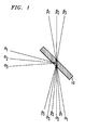
- FIG. 1 illustrates the principles of the invention.
- FIG. 1 shows two collimated arrays of light beams, designated generally as ⁇ and ⁇ , respectively, which are incident on opposite sides of an angle-variant device 10.
- angle-variant device 10 is a Fabry-Perot resonator (hereafter referred to as Fabry-Perot resonator 10).
- Array ⁇ which includes light beams ⁇ 1, ⁇ 2, and ⁇ 3, is substantially reflected from Fabry-Perot resonator 10 onto a target surface 12, which may be, for example, the surface of a device comprising an array of photodetectors.
- Array ⁇ which includes light beams ⁇ 1, ⁇ 2, and ⁇ 3, passes substantially without reflection through Fabry-Perot resonator 10 and onto target surface 12.
- the beams of array ⁇ strike Fabry-Perot resonator 10 at angles at which the resonator is highly reflective, while the beams of array ⁇ strike the resonator at angles at which the resonator is highly transmissive.
- Arrays ⁇ and ⁇ are oriented relative to one another and relative to Fabry-Perot resonator 10 such that transmission of one array of beams and reflectance of the other array of beams causes both arrays to be incident on target surface 12.
- the angle of incidence which is measured with respect to the normal to the surface of Fabry-Perot resonator 10, preferably is selected in the vicinity of 45 degrees so that Fabry-Perot resonator 10 reflects through a right angle.
- angles of incidence and resonator orientation could be used to combine the arrays of light beams.
- FIG. 2 shows an exemplary embodiment of apparatus for combining two arrays of substantially parallel light beams in accordance with the principles of the invention.
- the apparatus includes Fabry-Perot resonator 10, collimating lenses 14 and 16, and a focusing lens 18.
- Light beams emitted from sources a1, a2, and a3 are collimated by collimating lens 14.
- the collimated beams are directed to a first mirror surface 20 of Fabry-Perot resonator 10 and strike surface 20 at a family of angles corresponding to high reflectance.
- light beams from sources b1, b2, and b3 are collimated by collimating lens 16 and are directed to a second mirror surface 22 of Fabry-Perot resonator 10.
- the beams from sources b1, b2, and b3 strike surface 22 at a family of angles corresponding to high transmission. (Exemplary angles of incidence for light beam arrays ⁇ and ⁇ are described below and are shown in FIG. 6.)
- the positions of lenses 14 and 16 are selected to achieve the desired angles of incidence for the respective arrays of light beams.
- Lens 18 receives the reflected light beams of array ⁇ and the transmitted light beams of array ⁇ at different angles. Lens 18 focuses the beams to form the interleaved array of spots a1', b1', a2', b2', a3', and b3' on target surface 12. The positions of lenses 14 and 16 can be adjusted so that the spots are interleaved as shown in FIG. 2.
- FIGs. 3 and 4 show Fabry-Perot resonator 10 in greater detail and illustrate the angles of illustrative light beams in the resonator.
- a beam is incident at an angle ⁇ , relative to the normal, on a surface of Fabry-Perot resonator 10. More particularly, FIG. 3 shows light beam ⁇ 1 incident on surface 20 and FIG. 4 shows light beam ⁇ 1 incident on surface 22.
- the part of beam ⁇ 1 that is transmitted by surface 20 will propagate at an angle ⁇ ' relative to the normal to surface 20.
- the part of beam ⁇ 1 that is transmitted by surface 22 will propagate at an angle ⁇ ' relative to the normal to surface 22.
- the reflectivities of the front and back mirror surfaces 20 and 22 of Fabry-Perot resonator 10 are equal.
- the transmission T of the Fabry-Perot resonator is given by and the reflection S of the resonator is given by where
- R is the reflectivity of Fabry-Perot mirror surfaces 20 and 22
- ⁇ 0 is the free space wavelength of the lightwave
- n' is the refractive index of the medium separating mirror surfaces 20 and 22
- h is the distance between the mirror surfaces
- ⁇ ' is the angle between the light beam ( ⁇ 1 or ⁇ 1) and the normal to the mirror surfaces, as measured inside the medium. Phase changes of the lightwave on reflection off mirror surfaces 20 and 22 have been ignored, as they do not affect the principles of operation of the device.
- Fabry-Perot resonator 10 is highly transmitting for angles ⁇ ' such that where m is a resonance of the Fabry-Perot resonator.
- Snell's law one can deduce the external angle of incidence associated with the m th Fabry-Perot transmission resonance, The family of angles at which the light beams of array ⁇ are incident on Fabry-Perot resonator 10 (see FIG. 1) are selected from among this set of highly transmitting angles.
- the focal lengths f14, f16, and f18, respectively, of lenses 14, 16, and 18 are 1 cm.
- This wavelength is commonly used in optical systems using laser diodes to provide the optical power.
- These refractive indices correspond to a glass Fabry-Perot resonator 10 surrounded by air or vacuum.
- We choose to operate in the vicinity of ⁇ 45 degrees, so that Fabry-Perot resonator 10 reflects through a right angle.
- the thickness, h, of Fabry-Perot resonator 10 should be approximately 22.5 ⁇ m.
- Equation (4) can be written explicitly in terms of the external incident angle ⁇ to obtain the expression Using this expression and equations (1) and (2), the transmission T and the reflection S of Fabry-Perot resonator 10 can be calculated as a function of the incident angle ⁇ .
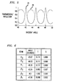
- FIG. 5 is a graph of the transmission and reflection values of Fabry-Perot resonator 10 using the design criteria described above.
- the graph clearly illustrates the angle-variant properties of Fabry-Perot resonator 10, showing high transmission peaks at one family of incident angles and high reflection peaks (interspersed between the high transmission peaks) at a second family of incident angles.
- the table of FIG. 6 shows the angles of incidence for beams ⁇ 1, ⁇ 2, ⁇ 3, ⁇ 1, ⁇ 2, and ⁇ 3 of FIG. 1, and the resulting transmission and reflection values, for the illustrative system and Fabry-Perot resonator design criteria described above. From FIG. 6 it can be shown that two equally-spaced sets of light sources can produce interleaved images, with the light beams from one set of sources (i.e., sources a1, a2, and a3 of FIG. 2) being reflected from the Fabry-Perot resonator 10 with greater than 88 percent reflectivity, while the light beams from the other set of sources (i.e., sources b1, b2, and b3 of FIG. 2) are transmitted with greater than 98 percent transmission.
- the angle-variant device can be designed so as to combine multiple arrays of light beams with little optical power loss.
- angle-variant device Fabry-Perot resonator
- the angle-variant device could be, for example, a diffractive optical device, such as a volume diffraction grating.
- diffractive optical device such as a volume diffraction grating
Landscapes
- Physics & Mathematics (AREA)
- General Physics & Mathematics (AREA)
- Optics & Photonics (AREA)
- Spectroscopy & Molecular Physics (AREA)
- Semiconductor Lasers (AREA)
- Optical Modulation, Optical Deflection, Nonlinear Optics, Optical Demodulation, Optical Logic Elements (AREA)
- Mechanical Light Control Or Optical Switches (AREA)
Applications Claiming Priority (2)
| Application Number | Priority Date | Filing Date | Title |
|---|---|---|---|
| US07/991,635 US5353155A (en) | 1992-12-16 | 1992-12-16 | Methods and apparatus for combining arrays of light beams |
| US991635 | 1992-12-16 |
Publications (3)
| Publication Number | Publication Date |
|---|---|
| EP0602832A2 true EP0602832A2 (fr) | 1994-06-22 |
| EP0602832A3 EP0602832A3 (fr) | 1995-07-12 |
| EP0602832B1 EP0602832B1 (fr) | 1999-02-24 |
Family
ID=25537413
Family Applications (1)
| Application Number | Title | Priority Date | Filing Date |
|---|---|---|---|
| EP93309627A Expired - Lifetime EP0602832B1 (fr) | 1992-12-16 | 1993-12-02 | Méthode et appareil pour combiner des faisceaux lumineux |
Country Status (4)
| Country | Link |
|---|---|
| US (1) | US5353155A (fr) |
| EP (1) | EP0602832B1 (fr) |
| JP (1) | JP2813123B2 (fr) |
| DE (1) | DE69323603T2 (fr) |
Families Citing this family (3)
| Publication number | Priority date | Publication date | Assignee | Title |
|---|---|---|---|---|
| JP4207554B2 (ja) * | 2002-12-12 | 2009-01-14 | 住友電気工業株式会社 | 光射出面上に回折光学膜を有する発光素子とその製造方法 |
| JP5018076B2 (ja) * | 2006-12-22 | 2012-09-05 | ソニー株式会社 | 光造形装置及び光造形方法 |
| US10766242B2 (en) * | 2017-08-24 | 2020-09-08 | General Electric Company | System and methods for fabricating a component using a consolidating device |
Family Cites Families (7)
| Publication number | Priority date | Publication date | Assignee | Title |
|---|---|---|---|---|
| US3970963A (en) * | 1975-05-01 | 1976-07-20 | Hughes Aircraft Company | Waveguide laser arrangement for generating and combining a plurality of laser beams |
| JPS60108802A (ja) * | 1983-11-18 | 1985-06-14 | Fuji Photo Film Co Ltd | 光ビ−ム合成方法及び装置 |
| US4940309A (en) * | 1987-04-20 | 1990-07-10 | Baum Peter S | Tessellator |
| JPS63316020A (ja) * | 1987-06-19 | 1988-12-23 | Nec Corp | コヒ−レント光の光軸を同軸に重ねる方法 |
| US4813762A (en) * | 1988-02-11 | 1989-03-21 | Massachusetts Institute Of Technology | Coherent beam combining of lasers using microlenses and diffractive coupling |
| JPH0339712A (ja) * | 1989-07-06 | 1991-02-20 | Nec Corp | 光ビーム結合器 |
| US5050954A (en) * | 1990-01-12 | 1991-09-24 | At&T Bell Laboratories | Multiport optical devices |
-
1992
- 1992-12-16 US US07/991,635 patent/US5353155A/en not_active Expired - Lifetime
-
1993
- 1993-12-02 EP EP93309627A patent/EP0602832B1/fr not_active Expired - Lifetime
- 1993-12-02 DE DE69323603T patent/DE69323603T2/de not_active Expired - Fee Related
- 1993-12-15 JP JP5342291A patent/JP2813123B2/ja not_active Expired - Fee Related
Also Published As
| Publication number | Publication date |
|---|---|
| DE69323603T2 (de) | 1999-10-14 |
| JP2813123B2 (ja) | 1998-10-22 |
| DE69323603D1 (de) | 1999-04-01 |
| JPH06222401A (ja) | 1994-08-12 |
| US5353155A (en) | 1994-10-04 |
| EP0602832B1 (fr) | 1999-02-24 |
| EP0602832A3 (fr) | 1995-07-12 |
Similar Documents
| Publication | Publication Date | Title |
|---|---|---|
| EP1291690B1 (fr) | Commutateur optique avec élément convergent | |
| US11243450B2 (en) | Saw modulator having optical power component for extended angular redirection of light | |
| CA1255945A (fr) | Dispositif optique comportant un miroir concave ou un reseau de diffraction concave | |
| US6204955B1 (en) | Apparatus for dynamic control of light direction in a broad field of view | |
| GB2127575A (en) | Optical wavelength-multiplexing and/or demultiplexing device | |
| US4723829A (en) | Optical wavelength demultiplexer | |
| US6483961B1 (en) | Dual refraction index collimator for an optical switch | |
| EP0378886A1 (fr) | Système optique | |
| US5194989A (en) | Dielectric combiner including first and second dielectric materials having indices of refraction greater than 2.0 | |
| US6832859B1 (en) | Free space optical system with multiple function detectors | |
| US5884995A (en) | Lighting system with a micro-telescope integrated in a transparent plate | |
| WO1997008792A1 (fr) | Systeme optique a passage multiple | |
| US4562462A (en) | Color laser printer with improved efficiency | |
| EP0602832A2 (fr) | Méthode et appareil pour combiner des faisceaux lumineux | |
| US20230408727A1 (en) | Folded optical paths incorporating metasurfaces | |
| GB2212936A (en) | Two waveband catadioptric system | |
| US4289377A (en) | Projecting apparatus | |
| US6400512B1 (en) | Refractive/reflective optical element multiple beam spacer | |
| EP1184700B1 (fr) | Système optique à agrandissement variable | |
| US4081210A (en) | Composite four-element lens system, particularly for use with laser beams | |
| JPH06208012A (ja) | 光接続素子 | |
| US6556360B2 (en) | Optical element and optical device having it | |
| US4513434A (en) | X-Ray reflective optical elements | |
| US7095962B2 (en) | Optical transmission system | |
| GB2537675A (en) | Waveguide for multispectral fusion |
Legal Events
| Date | Code | Title | Description |
|---|---|---|---|
| PUAI | Public reference made under article 153(3) epc to a published international application that has entered the european phase |
Free format text: ORIGINAL CODE: 0009012 |
|
| AK | Designated contracting states |
Kind code of ref document: A2 Designated state(s): DE FR GB |
|
| PUAL | Search report despatched |
Free format text: ORIGINAL CODE: 0009013 |
|
| AK | Designated contracting states |
Kind code of ref document: A3 Designated state(s): DE FR GB |
|
| 17P | Request for examination filed |
Effective date: 19951213 |
|
| 17Q | First examination report despatched |
Effective date: 19971103 |
|
| GRAG | Despatch of communication of intention to grant |
Free format text: ORIGINAL CODE: EPIDOS AGRA |
|
| GRAG | Despatch of communication of intention to grant |
Free format text: ORIGINAL CODE: EPIDOS AGRA |
|
| GRAH | Despatch of communication of intention to grant a patent |
Free format text: ORIGINAL CODE: EPIDOS IGRA |
|
| GRAH | Despatch of communication of intention to grant a patent |
Free format text: ORIGINAL CODE: EPIDOS IGRA |
|
| GRAA | (expected) grant |
Free format text: ORIGINAL CODE: 0009210 |
|
| AK | Designated contracting states |
Kind code of ref document: B1 Designated state(s): DE FR GB |
|
| ET | Fr: translation filed | ||
| REF | Corresponds to: |
Ref document number: 69323603 Country of ref document: DE Date of ref document: 19990401 |
|
| PLBE | No opposition filed within time limit |
Free format text: ORIGINAL CODE: 0009261 |
|
| STAA | Information on the status of an ep patent application or granted ep patent |
Free format text: STATUS: NO OPPOSITION FILED WITHIN TIME LIMIT |
|
| 26N | No opposition filed | ||
| PGFP | Annual fee paid to national office [announced via postgrant information from national office to epo] |
Ref country code: FR Payment date: 20011121 Year of fee payment: 9 |
|
| PGFP | Annual fee paid to national office [announced via postgrant information from national office to epo] |
Ref country code: GB Payment date: 20011126 Year of fee payment: 9 |
|
| PGFP | Annual fee paid to national office [announced via postgrant information from national office to epo] |
Ref country code: DE Payment date: 20011230 Year of fee payment: 9 |
|
| REG | Reference to a national code |
Ref country code: GB Ref legal event code: IF02 |
|
| PG25 | Lapsed in a contracting state [announced via postgrant information from national office to epo] |
Ref country code: GB Free format text: LAPSE BECAUSE OF NON-PAYMENT OF DUE FEES Effective date: 20021202 |
|
| PG25 | Lapsed in a contracting state [announced via postgrant information from national office to epo] |
Ref country code: DE Free format text: LAPSE BECAUSE OF NON-PAYMENT OF DUE FEES Effective date: 20030701 |
|
| GBPC | Gb: european patent ceased through non-payment of renewal fee | ||
| PG25 | Lapsed in a contracting state [announced via postgrant information from national office to epo] |
Ref country code: FR Free format text: LAPSE BECAUSE OF NON-PAYMENT OF DUE FEES Effective date: 20030901 |
|
| REG | Reference to a national code |
Ref country code: FR Ref legal event code: ST |