EP0602853A2 - Système et procédé de mise en oeuvre d'un appareil d'impression d'images multitons - Google Patents
Système et procédé de mise en oeuvre d'un appareil d'impression d'images multitons Download PDFInfo
- Publication number
- EP0602853A2 EP0602853A2 EP93309684A EP93309684A EP0602853A2 EP 0602853 A2 EP0602853 A2 EP 0602853A2 EP 93309684 A EP93309684 A EP 93309684A EP 93309684 A EP93309684 A EP 93309684A EP 0602853 A2 EP0602853 A2 EP 0602853A2
- Authority
- EP
- European Patent Office
- Prior art keywords
- station group
- station
- photoreceptor
- depositing
- groups
- Prior art date
- Legal status (The legal status is an assumption and is not a legal conclusion. Google has not performed a legal analysis and makes no representation as to the accuracy of the status listed.)
- Granted
Links
Images


Classifications
-
- G—PHYSICS
- G03—PHOTOGRAPHY; CINEMATOGRAPHY; ANALOGOUS TECHNIQUES USING WAVES OTHER THAN OPTICAL WAVES; ELECTROGRAPHY; HOLOGRAPHY
- G03G—ELECTROGRAPHY; ELECTROPHOTOGRAPHY; MAGNETOGRAPHY
- G03G15/00—Apparatus for electrographic processes using a charge pattern
- G03G15/01—Apparatus for electrographic processes using a charge pattern for producing multicoloured copies
-
- G—PHYSICS
- G03—PHOTOGRAPHY; CINEMATOGRAPHY; ANALOGOUS TECHNIQUES USING WAVES OTHER THAN OPTICAL WAVES; ELECTROGRAPHY; HOLOGRAPHY
- G03G—ELECTROGRAPHY; ELECTROPHOTOGRAPHY; MAGNETOGRAPHY
- G03G15/00—Apparatus for electrographic processes using a charge pattern
- G03G15/01—Apparatus for electrographic processes using a charge pattern for producing multicoloured copies
- G03G15/0142—Structure of complete machines
- G03G15/0147—Structure of complete machines using a single reusable electrographic recording member
- G03G15/0152—Structure of complete machines using a single reusable electrographic recording member onto which the monocolour toner images are superposed before common transfer from the recording member
-
- G—PHYSICS
- G03—PHOTOGRAPHY; CINEMATOGRAPHY; ANALOGOUS TECHNIQUES USING WAVES OTHER THAN OPTICAL WAVES; ELECTROGRAPHY; HOLOGRAPHY
- G03G—ELECTROGRAPHY; ELECTROPHOTOGRAPHY; MAGNETOGRAPHY
- G03G15/00—Apparatus for electrographic processes using a charge pattern
- G03G15/01—Apparatus for electrographic processes using a charge pattern for producing multicoloured copies
- G03G15/0142—Structure of complete machines
- G03G15/0147—Structure of complete machines using a single reusable electrographic recording member
- G03G15/0152—Structure of complete machines using a single reusable electrographic recording member onto which the monocolour toner images are superposed before common transfer from the recording member
- G03G15/0163—Structure of complete machines using a single reusable electrographic recording member onto which the monocolour toner images are superposed before common transfer from the recording member primary transfer to the final recording medium
Definitions
- the present invention relates to multitone imaging apparatus, and more particularly to apparatus having a photoreceptor and multiple units for depositing charge on the photoreceptor.
- a typical image printer may employ a latent development system having a photoconductive surface and a charging unit for depositing charge on the photoconductive surface. After being charged by the charging unit, the photoconductor surface is selectively exposed to a light pattern to selectively discharge the photoconductive surface, thereby producing a pattern of charge corresponding to an image. Subsequently, the photoconductive surface is exposed to charged toner, which adheres to charged portions of the photoconductor surface.
- the various parts of the printer tend to have a reduced size.
- reducing the size of the charging unit results in the charging unit being capable of depositing less charge per unit time. Reduced charge per unit time results in reduced image quality or in reduced printing speed.
- an imaging apparatus comprises a photoreceptor; a plurality of station groups, each station group including charge depositing means for depositing charge on the photoreceptor, exposing means for selectively exposing the photoreceptor to radiation; means for moving the photoreceptor relative to the plurality of stations; and means for selecting a station group and for disabling the exposing means in the selected station group and concurrently enabling the charge depositing means in the selected station group
- the present invention further provides an imaging apparatus comprising a photoreceptor; a plurality of station groups, each station group including charge depositing means for depositing charge on the photoreceptor, exposing means for selectively exposing the photoreceptor to radiation; means for operating in one of a first mode for concurrently enabling the depositing means of each station group to deposit charge at a common polarity, enabling the exposing means in a one of the station groups, enabling the exposing means in another one of the station groups, and moving the photoreceptor at a first speed relative to the plurality of stations, and a second mode for concurrently enabling the depositing means of each station group to deposit charge at the common polarity, disabling the exposing means in the one of the station groups, enabling the exposing means in the other one of the station groups, and moving the photoreceptor at a speed higher than the first speed relative to the plurality of stations.
- the present invention also provides an imaging apparatus comprising a photoreceptor; a plurality of station groups, each station group including charge depositing means for depositing charge on the photoreceptor, exposing means for selectively exposing the photoreceptor to radiation; means for operating in one of a first mode for concurrently enabling the depositing means of the one of the station groups to deposit charge of a first polarity at a first rate, enabling the exposing means in the one of the station groups, enabling the depositing means of the other one of the station groups to deposit charge of the first polarity at a second rate, enabling the exposing means in the other one of the station groups, and moving the photoreceptor at a first speed relative to the plurality of stations, and a second mode for concurrently enabling the depositing means of the one of the station groups to deposit charge of the first polarity at substantially the first rate, disabling the exposing means in the one of the station groups, enabling the depositing means of the other one of the station groups to deposit charge of the first polarity
- the plurality of station groups may include a first station group; a second station group, opposed to the first station group through the photoreceptor.
- the photoreceptor may be a flexible belt.
- the current invention provides, in an imaging apparatus having a photoreceptor, a plurality of station groups, each station group including charge depositing means for depositing charge on the photoreceptor, and exposing means for selectively exposing the photoreceptor to radiation, a method of operating the imaging apparatus comprising the steps of moving the photoreceptor relative to the plurality of stations; and selecting a station group and disabling the exposing means in the selected station group and concurrently enabling the charge depositing means in the selected station group.
- the present invention further provides a method of operating an imaging apparatus having a photoreceptor, and a plurality of station groups, each station group including charge depositing means for depositing charge on the photoreceptor, and exposing means for selectively exposing the photoreceptor to radiation, the method comprising the step of operating in one of a first mode for concurrently enabling the depositing means of each station group to deposit charge at a common polarity, enabling the exposing means in a one of the station groups, enabling the exposing means in another one of the station groups, and moving the photoreceptor at a first speed relative to the plurality of stations, and a second mode for concurrently enabling the depositing means of each station group to deposit charge at the common polarity, disabling the exposing means in the one of the station groups, enabling the exposing means in the other one of the station groups, and moving the photoreceptor at a speed higher than the first speed relative to the plurality of stations.
- the present invention also provides a method of operating an imaging apparatus having a photoreceptor, and a plurality of station groups, each station group including charge depositing means for depositing charge on the photoreceptor, and exposing means for selectively exposing the photoreceptor to radiation, the method comprising the step of operating in one of a first mode for concurrently enabling the depositing means of a one of the station groups to deposit charge of a first polarity at a first rate, enabling the exposing means in the one of the station groups, enabling the depositing means of another one of the station groups to deposit charge of the first polarity at a second rate, enabling the exposing means in the other one of the station groups, and moving the photoreceptor at a first speed relative to the plurality of stations, and a second mode for concurrently enabling the depositing means of the one of the station groups to deposit charge of the first polarity at substantially the first rate, disabling the exposing means in the one of the station groups, enabling the depositing means of the other one of the
- Fig. 1 shows a copier 1000 that has a height of 940 mm.
- an input scanner 1220 scans an original document on platen a 1210, to produce a latent image on a photoreceptor belt 1510 in photoreceptor assembly 1500, to be described in more detail below.
- a vacuum transport 1125 transports the paper to a fuser 1132, which permanently affixes the toner to the paper with heat and pressure. The paper then advances out of copier 1000, or to a paper tray 1130 allowing the paper to return to belt 1510 for printing an image on an opposite side of the paper.
- a controller 1350 controls photoreceptor assembly 1500 as described in more detail below.
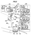
- Fig. 2 shows photoreceptor subassembly 1500 in more detail.
- Belt 1510 is entrained around rollers 2010-2028.
- Roller 2028 is rotated by a motor coupled to the roller by suitable means such as a belt drive (not shown)
- Roller 2028 advances belt 1510 in the direction of arrow 2333 through various processing stations disposed around the movement path of belt 1510.
- the preferred copier 1000 includes four groups of stations for printing in four colors, e.g., cyan, magenta, yellow and black.
- a station group 2100 includes charge scorotron 2110 having a single row of charge pins, a raster output scanning (ROS) laser assembly 2120, and a toner developer 2130. Developer 2130 employees a development system in which toner may transfer from the developer to belt 1510, without developer 2130 contacting belt 1510.
- ROS raster output scanning
- Another station group 2200 includes a scorotron 2210, a LED assembly 2220, and a developer 2230.
- a third station group 2300 includes a scorotron 2310, a LED assembly 2320, and a developer 2330.
- a fourth station group 2400 includes a scorotron 2410, a LED assembly 2420, and a developer 2430.
- LED assemblies 2220, 2320, and 2420 include a bar of LEDs arranged in a longitudinal configuration. Developers 2230, 2330 and 2430 are "scavangeless,” meaning that developers 2230, 2330 and 2430 do not remove toner that may already be present on belt 1510.
- copier 1000 includes a first station group 2100; a second station group 2200, located downstream from the first station group; a third station group 2300, located downstream from the second station group; and a fourth station group 2400, located downstream from the third station group.
- Developer 2430 may contain black toner, while developers 2130, 2230 and 2330 may contain cyan toner, magenta toner and yellow toner, respectively.
- Controller 1350 includes a general purpose processor, software, and circuitry for interfacing with variable speed photoreceptor drive motor 3070, which is mechanically coupled to belt 1510. Controller 1350 causes belt 1510 to be driven at various speeds, depending on the number of basic colors employed in the copy process, as described in more detail below.
- Controller 1350 also controls variable speed main drive motor 3020, which is mechanically coupled to developer 2130 through clutch 3030, to developer 2230 through clutch 3040, to developer 2330 through clutch 3050, and to developer 2430 through clutch 3060. Controller 1350 can selectively disable a developer, such as developer 2330 by disengaging clutch 3050.
- Scanner 1220 acquires an image that is subsequently decoded into four basic color signals.
- a first one of the color signals is used to drive ROS laser 2120, a second one of the color signals is used to drive LED assembly 2220, a third color signal is used to drive LED assembly 2320, and a fourth color signal is used to drive LED assembly 2420.
- Station group 2100 selectively deposits cyan toner on belt 1510. More specifically, a certain area of the belt 1510 passes by scorotron 2110 to charge belt 1510 to a relatively high, substantially uniform potential. Next, the area of the belt 1510 passes by ROS laser assembly 2120 to selectively expose the area of the belt 1510 to a pattern of light, thereby producing an electrostatic latent image. Next, the area of the belt passes developer 2130 to deposit cyan toner on charged areas of the belt.
- station groups 2200, 2300 and 2400 are similar to the processing of station group 2100, described above, except that station groups 2200, 2300, and 2400 employ LED bar assemblies instead of an ROS laser to selectively expose belt 1510 to light.
- Transfer scorotron 2515 charges a sheet of paper to an appropriate magnitude and polarity so that the paper is tacked to belt 1510 and the toner attracted from belt 1510 to the paper.
- detack scorotron 2520 charges the paper to an opposite polarity to detack the paper from belt 1510.
- the paper is then advanced to fuser 1132, which permanently affixes the toner to the copy sheet with heat and pressure.
- Blade/brush cleaner 2535 removes toner remaining on belt 1510 after the paper is detacked from belt 1510.
- Controller 1350 fully enables one of the station groups and partially enables the other threestation groups. More specifically, controller 1350 enables scorotron 2410 LED assembly 2420, and developer 2430, of station group 2400. Controller 1350 disables developers 2130, 2230 and 2330 by disengaging clutches 3030, 3040 and 3050, respectively; and disables ROS laser 2120, LED assembly 2220 and LED assembly 2320. Controller 1350 enables scorotrons belonging to the station groups of the disabled developers, scorotrons 2110, 2210 and 2310.
- controller 1350 operates to concurrently select the first, second and third station groups, and to disable the developers and exposing elements in the selected groups.
- this single tone print mode four times the effective charge deposition rate can be achieved, as compared to the four tone printing mode.
- This higher charge deposition rate allows controller 1510 to cause belt 1510 to be propelled at a higher speed. For example, if the speed of belt 1510 in the four tone mode is 2.5 inches per second, or 10 color prints per minute, in the single tone mode only mode the speed of belt 1510 may be 10 inches per second, allowing 40 single tone prints per minute.
- controller 1350 operates to move belt 1510 at a first speed when controller 1350 selects one of the station groups to disable the developer in the selected station group, and operates to move belt 1510 at a speed lower than the first speed when controller 1510 does not operate to disable a developer.
- station groups 2100 and 2300 may be partially enabled, by enabling scorotrons 2110 and 2310. In this two tone mode, station groups 2200 and 2400 are fully enabled.
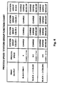
- Fig. 4 is a chart summarizing the three operating modes of copier 1000.
- all four station groups operate to charge belt 1510, expose photoreceptor belt 1510 to light, and develop photoreceptor belt 1510 by depositing toner.
- all four station groups operate to charge belt 1510, while only two station groups operate to expose and develop belt 1510.
- only one tone is employed in the print process
- all four station groups operate to charge belt 1510, while only one station group operates to expose and develop photoreceptor belt 1510.
Landscapes
- Physics & Mathematics (AREA)
- General Physics & Mathematics (AREA)
- Color Electrophotography (AREA)
- Control Or Security For Electrophotography (AREA)
- Combination Of More Than One Step In Electrophotography (AREA)
Applications Claiming Priority (2)
| Application Number | Priority Date | Filing Date | Title |
|---|---|---|---|
| US07/992,684 US5313259A (en) | 1992-12-18 | 1992-12-18 | System and method for operating a multitone imaging apparatus |
| US992684 | 1997-12-17 |
Publications (3)
| Publication Number | Publication Date |
|---|---|
| EP0602853A2 true EP0602853A2 (fr) | 1994-06-22 |
| EP0602853A3 EP0602853A3 (en) | 1995-09-13 |
| EP0602853B1 EP0602853B1 (fr) | 1997-03-26 |
Family
ID=25538628
Family Applications (1)
| Application Number | Title | Priority Date | Filing Date |
|---|---|---|---|
| EP93309684A Expired - Lifetime EP0602853B1 (fr) | 1992-12-18 | 1993-12-03 | Système et procédé de mise en oeuvre d'un appareil d'impression d'images multitons |
Country Status (4)
| Country | Link |
|---|---|
| US (1) | US5313259A (fr) |
| EP (1) | EP0602853B1 (fr) |
| JP (1) | JPH0772697A (fr) |
| DE (1) | DE69309237T2 (fr) |
Cited By (4)
| Publication number | Priority date | Publication date | Assignee | Title |
|---|---|---|---|---|
| EP0818716A3 (fr) * | 1996-07-09 | 1998-06-10 | Aetas Peripheral Corporation | Appareil électrophotographique à couleurs |
| EP0883036A3 (fr) * | 1997-06-05 | 1998-12-30 | Xeikon Nv | Appareil à imprimer électrostatographique avec une bande d'enregistrement sans fin |
| EP1107071A3 (fr) * | 1999-11-30 | 2003-12-03 | Canon Kabushiki Kaisha | Appareil de formation d'images |
| EP1548513A2 (fr) | 2003-12-23 | 2005-06-29 | Xerox Corporation | Systèmes et méthodes de diagnose des appareils de formation d'images en couleur |
Families Citing this family (17)
| Publication number | Priority date | Publication date | Assignee | Title |
|---|---|---|---|---|
| JPH08185005A (ja) * | 1994-12-28 | 1996-07-16 | Matsushita Electric Ind Co Ltd | カラー画像形成装置 |
| US5870649A (en) * | 1997-05-27 | 1999-02-09 | Ricoh Technology Research, Inc. | Image forming apparatus having an intermediate transfer belt with variable moving speed immediately following toner development |
| US6038411A (en) * | 1996-05-27 | 2000-03-14 | Ricoh Technology Research, Inc. | Image forming apparatus having an intermediate transfer belt with variable moving speed |
| US6249305B1 (en) * | 1997-05-16 | 2001-06-19 | Konica Corporation | Color image forming apparatus |
| US6088557A (en) * | 1997-06-05 | 2000-07-11 | Xeikon Nv | Electrostatographic printing apparatus with endless recording belt |
| US6108510A (en) * | 1997-06-20 | 2000-08-22 | Minolta Co., Ltd. | Tandem-type image forming apparatus having full-color print mode and single-color print mode |
| JP3455067B2 (ja) * | 1997-07-01 | 2003-10-06 | シャープ株式会社 | カラー画像形成装置 |
| US5946533A (en) * | 1998-12-16 | 1999-08-31 | Xerox Corporation | Printing machine architecture |
| US6198890B1 (en) | 1999-10-06 | 2001-03-06 | Aetas Technology Corporation | Electrophotographic color printing arrangement with inclined photoreceptor path |
| JP2001209232A (ja) * | 1999-11-19 | 2001-08-03 | Sharp Corp | カラー画像形成装置 |
| US6418286B1 (en) | 2000-11-06 | 2002-07-09 | Xerox Corporation | Electrostatographic reproduction machine having a belt conicity reducing assembly |
| JP2002207341A (ja) * | 2000-11-13 | 2002-07-26 | Canon Inc | 画像形成装置 |
| US6484004B1 (en) * | 2000-11-27 | 2002-11-19 | Aetas Technology, Incorporated | Method and apparatus for stabilizing the charge-to-mass ratio of various toner components in a multi-toner tone-on-tone electrophotographic device |
| US7136613B2 (en) * | 2003-03-10 | 2006-11-14 | Brother Kogyo Kabushiki Kaisha | Multicolor image forming apparatus and image making device |
| US7526229B1 (en) | 2007-12-27 | 2009-04-28 | Aetas Technology Incorporated | Belt tension mechanism of an image forming device |
| US7894731B2 (en) * | 2008-08-25 | 2011-02-22 | Xerox Corporation | Method by which an infinite number of colors may be used with a finite number of CCUs |
| DE102009034107B3 (de) * | 2009-07-21 | 2011-04-28 | Eastman Kodak Company | Entwicklervorrichtung |
Family Cites Families (13)
| Publication number | Priority date | Publication date | Assignee | Title |
|---|---|---|---|---|
| DE2446238A1 (de) * | 1974-09-27 | 1976-04-08 | Agfa Gevaert Ag | Elektrostatisches farb-kopiergeraet |
| JPS5627164A (en) * | 1979-08-11 | 1981-03-16 | Ricoh Co Ltd | Two color electrophotographic copier |
| JPS57188061A (en) * | 1981-05-15 | 1982-11-18 | Hitachi Ltd | Electrophotographing device |
| US4578331A (en) * | 1983-07-11 | 1986-03-25 | Ricoh Company, Ltd. | Color image forming method |
| JPS60229052A (ja) * | 1984-04-27 | 1985-11-14 | Toshiba Corp | 画像形成装置 |
| US4734735A (en) * | 1985-08-23 | 1988-03-29 | Konishiroku Photo Industry Co., Ltd. | Image apparatus having a color separation function |
| US4789612A (en) * | 1986-03-06 | 1988-12-06 | Konishiroku Photo Industry Co., Ltd. | Method for forming color image |
| JPS63296063A (ja) * | 1987-05-28 | 1988-12-02 | Canon Inc | 画像形成装置 |
| JPS6478267A (en) * | 1987-09-19 | 1989-03-23 | Sanyo Electric Co | Copying device |
| US4952978A (en) * | 1988-07-11 | 1990-08-28 | Canon Kabushiki Kaisha | Speed control of color development in electrophotographic process and apparatus |
| US4987455A (en) * | 1989-11-22 | 1991-01-22 | Eastman Kodak Company | Multicolor imaging apparatus |
| US5134444A (en) * | 1990-05-15 | 1992-07-28 | Minolta Camera Kabushiki Kaisha | Image forming apparatus |
| JP2981913B2 (ja) * | 1990-08-22 | 1999-11-22 | コニカ株式会社 | カラー画像形成装置 |
-
1992
- 1992-12-18 US US07/992,684 patent/US5313259A/en not_active Expired - Fee Related
-
1993
- 1993-12-03 DE DE69309237T patent/DE69309237T2/de not_active Expired - Fee Related
- 1993-12-03 EP EP93309684A patent/EP0602853B1/fr not_active Expired - Lifetime
- 1993-12-06 JP JP5305301A patent/JPH0772697A/ja active Pending
Cited By (6)
| Publication number | Priority date | Publication date | Assignee | Title |
|---|---|---|---|---|
| EP0818716A3 (fr) * | 1996-07-09 | 1998-06-10 | Aetas Peripheral Corporation | Appareil électrophotographique à couleurs |
| EP0883036A3 (fr) * | 1997-06-05 | 1998-12-30 | Xeikon Nv | Appareil à imprimer électrostatographique avec une bande d'enregistrement sans fin |
| EP1107071A3 (fr) * | 1999-11-30 | 2003-12-03 | Canon Kabushiki Kaisha | Appareil de formation d'images |
| EP1548513A2 (fr) | 2003-12-23 | 2005-06-29 | Xerox Corporation | Systèmes et méthodes de diagnose des appareils de formation d'images en couleur |
| EP1548513A3 (fr) * | 2003-12-23 | 2006-04-26 | Xerox Corporation | Systèmes et méthodes de diagnose des appareils de formation d'images en couleur |
| US7324767B2 (en) | 2003-12-23 | 2008-01-29 | Xerox Corporation | Systems and methods for diagnosing color image forming devices |
Also Published As
| Publication number | Publication date |
|---|---|
| US5313259A (en) | 1994-05-17 |
| JPH0772697A (ja) | 1995-03-17 |
| DE69309237D1 (de) | 1997-04-30 |
| DE69309237T2 (de) | 1997-08-14 |
| EP0602853A3 (en) | 1995-09-13 |
| EP0602853B1 (fr) | 1997-03-26 |
Similar Documents
| Publication | Publication Date | Title |
|---|---|---|
| EP0602853B1 (fr) | Système et procédé de mise en oeuvre d'un appareil d'impression d'images multitons | |
| US5270783A (en) | Image forming equipment having improved toner sensing | |
| US6434354B2 (en) | Image forming apparatus | |
| EP0163791A1 (fr) | Appareil xérographique à couleurs | |
| GB2127744A (en) | Multicolour printing | |
| US5070372A (en) | Method and apparatus of forming combined toner images | |
| US6167224A (en) | Method for applying uniform gloss over the entire print | |
| EP1126331B1 (fr) | Dispositif de formation d'image permettant de compenser un matériau plus épais pour l'enregistrement d'images par rapport à sa capacité thermique en utilisant une plus petite quantité de toner | |
| US6249656B1 (en) | Image forming apparatus that reduces test toner cleaning | |
| JP3325071B2 (ja) | 画像形成装置 | |
| US7667861B2 (en) | Image forming apparatus | |
| US5729808A (en) | Image forming method and apparatus which controls the discharging of toner images before transfer | |
| US5493381A (en) | Optimizing preclean corona current for cleaning multiple toners | |
| US5565974A (en) | Penta-level xerographic unit | |
| US7471922B2 (en) | Segmented transfer assist blade | |
| EP0588552B1 (fr) | Méthode et appareil pour charger une surface photoconductrice à un potentiel uniforme | |
| US5734951A (en) | Image forming apparatus | |
| US5867635A (en) | Selectable quality control and productivity in a color reprographic printing machine | |
| JPH112934A (ja) | 画像形成装置 | |
| JPH07210011A (ja) | 画像形成装置 | |
| JPH06149057A (ja) | 画像形成装置 | |
| JPH07306561A (ja) | タンデムエンジンタイプのカラー画像形成装置 | |
| JP3267009B2 (ja) | カラー画像形成装置 | |
| JPH07134531A (ja) | 複写機の動作制御方法 | |
| JP3452293B2 (ja) | 画像形成装置 |
Legal Events
| Date | Code | Title | Description |
|---|---|---|---|
| PUAI | Public reference made under article 153(3) epc to a published international application that has entered the european phase |
Free format text: ORIGINAL CODE: 0009012 |
|
| AK | Designated contracting states |
Kind code of ref document: A2 Designated state(s): DE FR GB |
|
| PUAL | Search report despatched |
Free format text: ORIGINAL CODE: 0009013 |
|
| AK | Designated contracting states |
Kind code of ref document: A3 Designated state(s): DE FR GB |
|
| 17P | Request for examination filed |
Effective date: 19960313 |
|
| GRAG | Despatch of communication of intention to grant |
Free format text: ORIGINAL CODE: EPIDOS AGRA |
|
| 17Q | First examination report despatched |
Effective date: 19960805 |
|
| GRAH | Despatch of communication of intention to grant a patent |
Free format text: ORIGINAL CODE: EPIDOS IGRA |
|
| GRAH | Despatch of communication of intention to grant a patent |
Free format text: ORIGINAL CODE: EPIDOS IGRA |
|
| GRAA | (expected) grant |
Free format text: ORIGINAL CODE: 0009210 |
|
| AK | Designated contracting states |
Kind code of ref document: B1 Designated state(s): DE FR GB |
|
| REF | Corresponds to: |
Ref document number: 69309237 Country of ref document: DE Date of ref document: 19970430 |
|
| ET | Fr: translation filed | ||
| PLBE | No opposition filed within time limit |
Free format text: ORIGINAL CODE: 0009261 |
|
| STAA | Information on the status of an ep patent application or granted ep patent |
Free format text: STATUS: NO OPPOSITION FILED WITHIN TIME LIMIT |
|
| 26N | No opposition filed | ||
| PGFP | Annual fee paid to national office [announced via postgrant information from national office to epo] |
Ref country code: GB Payment date: 20011205 Year of fee payment: 9 |
|
| PGFP | Annual fee paid to national office [announced via postgrant information from national office to epo] |
Ref country code: FR Payment date: 20011212 Year of fee payment: 9 |
|
| PGFP | Annual fee paid to national office [announced via postgrant information from national office to epo] |
Ref country code: DE Payment date: 20011217 Year of fee payment: 9 |
|
| REG | Reference to a national code |
Ref country code: GB Ref legal event code: IF02 |
|
| PG25 | Lapsed in a contracting state [announced via postgrant information from national office to epo] |
Ref country code: GB Free format text: LAPSE BECAUSE OF NON-PAYMENT OF DUE FEES Effective date: 20021203 |
|
| PG25 | Lapsed in a contracting state [announced via postgrant information from national office to epo] |
Ref country code: DE Free format text: LAPSE BECAUSE OF NON-PAYMENT OF DUE FEES Effective date: 20030701 |
|
| GBPC | Gb: european patent ceased through non-payment of renewal fee | ||
| PG25 | Lapsed in a contracting state [announced via postgrant information from national office to epo] |
Ref country code: FR Free format text: LAPSE BECAUSE OF NON-PAYMENT OF DUE FEES Effective date: 20030901 |
|
| REG | Reference to a national code |
Ref country code: FR Ref legal event code: ST |