EP0602913B1 - Verfahren zur Verwendung von Mehrfacheingabegriffeln in einem Mehrfachrechnersystem - Google Patents
Verfahren zur Verwendung von Mehrfacheingabegriffeln in einem Mehrfachrechnersystem Download PDFInfo
- Publication number
- EP0602913B1 EP0602913B1 EP93309995A EP93309995A EP0602913B1 EP 0602913 B1 EP0602913 B1 EP 0602913B1 EP 93309995 A EP93309995 A EP 93309995A EP 93309995 A EP93309995 A EP 93309995A EP 0602913 B1 EP0602913 B1 EP 0602913B1
- Authority
- EP
- European Patent Office
- Prior art keywords
- computer
- input
- signature
- signal
- screen
- Prior art date
- Legal status (The legal status is an assumption and is not a legal conclusion. Google has not performed a legal analysis and makes no representation as to the accuracy of the status listed.)
- Expired - Lifetime
Links
Images


Classifications
-
- G—PHYSICS
- G06—COMPUTING OR CALCULATING; COUNTING
- G06F—ELECTRIC DIGITAL DATA PROCESSING
- G06F3/00—Input arrangements for transferring data to be processed into a form capable of being handled by the computer; Output arrangements for transferring data from processing unit to output unit, e.g. interface arrangements
- G06F3/01—Input arrangements or combined input and output arrangements for interaction between user and computer
- G06F3/03—Arrangements for converting the position or the displacement of a member into a coded form
- G06F3/033—Pointing devices displaced or positioned by the user, e.g. mice, trackballs, pens or joysticks; Accessories therefor
- G06F3/038—Control and interface arrangements therefor, e.g. drivers or device-embedded control circuitry
Definitions
- the invention relates to a method for interactively interfacing with a system comprising multiple computers. More specifically, the invention relates to techniques for providing a multiple-computer system with multiple input styli, each stylus being able to interface with any one of multiple computer displays in the system.
- the stylus is placed against a piece of some signal medium, typically with a large surface area, which performs the conjugate function.
- a piece of specially prepared glass might cover a computer display, or be incorporated as a computer display screen. Either case may be referred to as a "display screen.”
- the stylus may measure a signal which varies across the glass surface.
- the stylus may emit a signal which is measured at the perimeter of the glass. In either case, the position of the stylus can be calculated.
- the system consists of a signal source, a signal detector, and an interface to a computer.
- a square wave may be generated by the stylus or screen, and the receiving screen or stylus detector converts the serial data into digital words which indicate position.
- the sending apparatus, and the receiving apparatus that belongs to it, must share a common time base for the encoded data to be correctly recognized.
- Various display systems which incorporate the capability for printing or writing onto a display screen, with a detector for sensing and encoding the location of the input device on the display screen and accurately determining input coordinate positions.
- US-A-3,857,022 acoustically locates the position of a stylus tapped against a screen.
- US-A-4,514,688 determines the distance of a pointer position from a predetermined reference point by measuring magnetostrictively induced strain waves.
- US-A-No. 4,839,634 describes a portable electro-optic device preferably comprising a flat panel display, pen-sensing surface, and a pen, with means provided for sensing and encoding the position of the pen on the display surface.
- US-A-4,678,869 describes an apparatus, system and method which employ a surface which is excited with an a.c. source at terminal locations disposed at the edges of the surface. Reducing the area of grid elements at crossover positions and intermediate grounding terminals minimizes disruptive potential caused by capacitive coupling.
- a correction look-up table is developed as part of the manufacture of the apparatus to provide a regularly incremented sequence of address values developed from a signal domain computation.
- US-A-4,650,926 provides correction for graphic surface non-linearities in an electrographic system wherein output readings are taken along a physical domain rectangular grid array, and these output readings are adjusted in their signal domain to establish a regularly incremented sequence of address values.
- Some systems may incorporate multiple input styli for a single computer by supplying identifying information in the encoded bitstream.
- An acoustic signal from each stylus is designed to be easy to convert to a location, and each contains a distinctive identification code so that the system can determine which stylus is the signal source.
- EP-A 0 365 918 discloses a data processing system which is equipped with a secure user friendly input system.
- the input system comprises an array of horizontal and vertical conductor supported on a flexible, transparent overlay membrane secured to the viewing surface of the display of an individual workstation and a remotely sensed personal stylus.
- the stylus is equipped to receive electromagnetic signals from the array and transmit signals containing information concerning the stylus position on the overlay and stylus ID to a receiver at the workstation.
- the input system also includes a control processor operating in stored program instructions which control the detection and log-on procedures for the remotely sensed personal stylus.
- One aspect that all of the above-mentioned systems have in common is that the device or devices supplying input signals and the device receiving the signals must share a common time base in order for the input signal to be correctly recognized.
- a user using a first computer would like to use the stylus belonging to that first computer to indicate an input action on any of the family of computers in the multiple-computer system.
- a user of a portable computer with a pen input may walk up to a display for a second user's computer.
- the first user would like to indicate an input location on the second user's display, and points to the location on the second display with the pen from the first computer.
- all pens in a system are able to determine which computer they are writing on and an input position relative to that input computer, regardless of whether they belong to that computer, by determining an identifying "signature" of the computer.
- Each stylus is able to communicate with the software entity which can correctly interpret the measurement by using a computer network.
- Each stylus must be able to participate in the measurement of its location on any computer in the system, without sharing a time base with that computer.
- the invention provides a method for the input device to discern useful information concerning position even though that device belongs to another computer.
- the invention additionally provides an input signal to the system which contains information about the input device source allowing the computer being acted upon the ability to distinguish what computer device is providing the input, so that that computer can determine access rights and other information relating to the input device. Both frequency- and time-domain calculations may be used to recover stylus position and signal source information from the stylus detection measurements.
- the invention provides a position input device which can be used with one or more computer video display terminals which are each indicative of the display of a different computer.
- the input device of the invention employs a pointer as composite-signal receiver.
- the device according to the invention may employ more than one pointer at a time, with each pointer resulting in a distinct position input.
- a method for using a position input device connected to a first computer to indicate a location on a second computer in a system of multiple computers connected to each other through a network.
- a composite signal comprising distinguishable components indicative of the signature of the source and position of an input location is produced.
- An input location is selected on the second computer display screen with the input device of the first computer, and a signal is sensed at that position.
- the distinguishable components in the composite signal are used to determine relative coordinates of the input location on the second computer.
- the invention provides input styli which participate in measurement of location on a computer display without sharing a time base with that computer. Further, there is provided a multiple-computer system in which the input device belonging to any individual computer in the system is able to input information including location on any of the family of computers in the multiple-computer system.
- Input information to a computer from individual input styli not necessarily connected directly to that computer may be distinguished, so that the computer may concurrently recognize the location and identities of each of one or more input styli.
- the invention allows an input stylus to input position information to a computer that it is not necessarily connected to.
- Fig. 1 shows a computer system 10 comprising at least two computers 14 and 20, connected for communicating via a communication network 12.
- An input device 16 is "connected to,” or “belongs to,” computer 14, and a second input device 22 belongs to computer 20.
- input device 16 is shown as a stylus device, connected by a wire 18 to computer 14. It is clear that it need not necessarily be connected by a wire, but could also be connected to the computer it belongs to via infrared or radio-type signals, for example.
- stylus 16 would only be recognizable as an input device for computer 14, to which it belongs.
- the stylus and computer typically share a time base to allow recognition of parameters of the computer.
- a stylus which is not familiar with the time parameters of a given computer would not be able to discern any useful information from the signals transmitted by that computer.
- Fig. 7 shows a block diagram of a system according to a preferred embodiment of the invention.
- the block diagram shows a computer 112 which is connected to a multiple-computer system 152 through a network connection 150.
- This connection could be any kind of system network, such as a wired or wireless local area network (LAN).
- Computer 112 has connected to it display 122 and input stylus 140.
- the screen of display 122 comprises of a piece of glass with a resistive coating with a ring of metal electrodes, such as is found on many available "pen input" computer systems.
- Input stylus 140 is a solid brass pen device such as is used in some pen input systems. The brass tip provides a good conducting surface that is relatively soft and has no particles or sharp edges to scratch the resistive coating of the glass.
- Display RAM 114 contains information for displaying an image on a screen of the display 122 as well as for generating frequency information which will enable a sensing input device to tell which display it is touching and approximate location coordinates for the position it is pointing to.
- the display RAM 114 is divided into sections which contain information for the top and bottom halves of a liquid crystal display (LCD). This data is used to form the image in display image driver 120, which is shown on LCD 122.
- LCD liquid crystal display
- Input stylus 140 picks up signals from a screen (which may be the screen of display 122, or the screen of the display from another computer [not shown] in the system 152), which are detected and converted into frequency component indicators by detector 142. The resulting frequency components are used by an identity and position logic 144 to determine the source and relative input position data. This data may be acted upon by computer 112 if it is determined to be the source, or the data may be sent via network 150 to the appropriate source computer (not shown) in computer system 152. Function selection information may also be supplied via input stylus 140.
- Fig. 2 illustrates schematically a display screen 30, as might be associated with the system according to the preferred embodiment.
- Screen 30, outlined in solid lines, has electrodes 32, 36, 38, 40, shown as black squares at the corners, which are used to supply electrical signals to the screen 30.
- the geometry of the screen 30 is not limited to the shape shown, and the screen 30 may have many more than four electrodes along the edges of the screen 30, may use electrodes located at the midpoints of the screen 30, and the electrodes might be wide as well as point electrodes. However, for the purpose of the discussion of the preferred embodiment, it is convenient to consider only four point electrodes, one at each of four corners of a rectangular screen 30.
- the electrical field represents a rectangular grid array of input locations.
- the grid array being illustrated by dashed grid lines 42, 44. This is done by supplying a sine wave signal of a first frequency f 1 at a given peak voltage, say 1 V, to one edge of the screen 30 from two electrodes such as 32 and 36. A signal of the same frequency f 1 , but half the voltage (1 ⁇ 2 V), is supplied to the screen 30 from the opposite edge, i. e. electrodes 38 and 40. This will form an electrical field of frequency f 1 that is stronger at grid line 42, towards the edge of electrodes 32 and 36, and weaker at grid line 44, towards the edge of electrodes 38 and 40.
- a signal of a second frequency f 2 is supplied in the same way but from opposite sides, so that f 2 is strong at grid line 44, towards the edge of 38 and 40, and weaker at grid line 42, towards the edge of 32 and 36.
- a signal of a third frequency f 3 is supplied to the screen 30 so that it is strong at the top of the screen 30 at the edge of 32 and 40, and weaker near the bottom edge of 36 and 38.
- a signal of a fourth frequency f 4 is supplied to the screen 30 so that it is strong at the bottom of the screen 30 at the edge of 36 and 38, and weaker near the top edge of 32 and 40.
- a signal is supplied to the screen 30 which contains a composite signal of the signal of the frequencies f 1 , f 2 , f 3 , and f 4 .
- the signal on the screen 30 at electrode 32 may be described by: f 1 (1 V) + f 2 (1 ⁇ 2 V) + f 3 (1 V) + f 4 (1 ⁇ 2 V).
- Each electrode 32, 36, 38, 40 will have a slightly different composite signal.
- the signal at electrode 36 may be described by: f 1 (1 V) + f 2 (1 ⁇ 2 V) + f 3 (1 ⁇ 2 V) + f 4 (1 V).
- the result of supplying the composite signals to the glass will be an approximately linear electrical pattern illustrated by grid lines 42, 44. Additional composite signals may be supplied to additional electrodes, perhaps forming diagonal patterns, to increase the positional accuracy.
- the position of input point 46 can be determined by measuring the composite signal at input point 46, and detecting the peak signal strength of each frequency within the composite signal. So that the user is able to determine both the position and gain of the signals, there must be at least two frequencies in each dimension to determine the two unknown values. A ratio of the signal strength of the two signals in each dimension may be used to determine the position in that dimension.
- a signal of another frequency may be added equally to the composite signals at each electrode 32, 36, 38, 40 and will have approximately the same peak signal strength at that frequency at all positions across the screen 30.
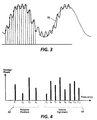
- signal 52 is a composite of sine waves.
- FFT fast Fourier transform
- each energy component represents the amplitude of the signal at that frequency.
- These components may be used to determine the position 46, on the screen 30, of the input device detecting these frequencies, as well as a "signature" of amplitude components of the frequencies in a pattern which identifies the source of the signal, i. e. the display.
- signals f 1 , f 2 , f 3 , and f 4 as discussed in relation to the description in Fig. 2 may produce component set 62 which indicates position on the screen 30.
- Further frequencies f 5 , f 6 , f 7 , f 8 , f 9 , f 10 , f 11 , and f 12 may be added to the composite signals.
- frequencies f 5 , f 6 , f 7 , f 8 , f 9 , f 10 , f 11 , and f 12 would be added, as described above, equally at each electrode 32, 36, 38, 40, so that the signature of the screen 30 would be the same at all positions on the screen 30.
- Different frequencies within a band of frequencies, or similar frequencies with different amplitudes or phase, may be applied for each different screen, thereby producing a different signature for each screen and computer.
- Each screen must have a distinguishable digital signature, controlled by the frequencies generated on the screen.
- the screen which is being pointed to by the input device can be identified by any other computer which is pointing to it by identifying its signature.
- the components are shown in sets 62 and 64 for illustrative purposes. Clearly, the frequencies and amplitudes for identifying position and signature may be interchanged or interleaved as appropriate for the system.
- each computer screen may be identified by the frequencies that are used for position location (i. e., one computer may use f n 1 , f n 2 , f n 3 , and f n 4 , and a second computer use f k 1 , f k 2 , f k 3 , and f k 4 .)
- the signal strengths may indicate relative position, while the frequencies used may themselves indicate the signature of the screen.
- the number of possible frequency combinations would then be limited, so that the number of separately distinguishable computers in the system must be limited. Considering the peak signal strength of each frequency in determining the signature determination, and using separate signals for position determination, allows a significantly higher number of computers to be used in the system than if the frequency alone is indicative of the signature.
- time-domain signals may be used to supplement frequency-domain information.
- binary data describing the signal source "signature" might be used to vary the amplitude of a signal at a frequency, the amplitude variation being repeated indefinitely.
- the computer receiving the signal from the input device will track the amplitude of the signal at that frequency until the complete series of amplitude variation is recorded. This series of amplitude variations then is used to identify the signature of the source.
- display RAM 114 also contains a data area 130 that stores data which is used to generate frequency data for the screen, which is used for providing the input position information and the signature of the screen.
- data area 130 that stores data which is used to generate frequency data for the screen, which is used for providing the input position information and the signature of the screen.
- eight individual bits of data are used to provide eight independent signal sources. These sources can be used to control eight separate electrodes on the screen.
- Each of the eight data lines provides pulse-code-modulated digital data through data integrators 132, which may be low pass filters, to derive analog frequency screen signals 134 which are supplied to the electrodes on the screen as described in relation to Fig. 2.
- the actual frequencies used in a system will be dependent upon many engineering factors, including but not limited to the technology of the screen and input devices, optimum voltages for the devices used and power requirements of the system.
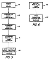
- Figs. 5 and 6 describe a method of obtaining the information as described in relation to Figs. 3 and 4.
- the steps in Fig. 5 are performed by the computer which is connected with the input device, such as by computer 14 and stylus 16 shown in Fig. 1. This need not necessarily be the same computer which the input device is getting information from.
- an input signal such as signal 52 in Fig. 3, is received.
- this analog signal 52 is converted into energy components versus frequency information, such as set 64 in Fig. 4, indicative of the frequencies in the signal using standard signal processing techniques.
- component set 64 information is used to determine the signature of the input signal, and therefore, the signature and identity of the source.
- the computer may also distinguish a stylus signature or function selection information, depending on the needs and capabilities of the system.
- step 86 component set 62 information is used to determine a "raw (x,y)" input point location based on the ratio of the frequency amplitudes.
- step 88 this raw (x,y) value is sent, with any additionally obtained function or stylus information, to the appropriate source computer as determined from the source signature via the network connection of the system.
- step 100 the raw (x,y) point location is received.
- step 102 the correction factors which apply to that specific surface are used with the raw (x,y) location to obtain an actual position on the screen. These correction factors may be previously determined by any of the many well-known methods for normalizing a screen, such as used in US-A-4,678,869 or US-A-4,650,926.
- Function or selection information from the input device may be added to the input signal, detected by the connected computer, and transmitted to the source computer along with the location information.
- the method is designed to enable a system with large numbers of individual computers, each separately distinguishable by the screen signature of the computer display or displays connected to that computer.
- the system is not limited to computers with single input styli devices.
- a computer with two or more styli which belong to it could perform the method of the invention for each of its styli, providing information to the source computer indicating which individual styli selected the input position along with computer and position identification information as described above.
Landscapes
- Engineering & Computer Science (AREA)
- General Engineering & Computer Science (AREA)
- Theoretical Computer Science (AREA)
- Human Computer Interaction (AREA)
- Physics & Mathematics (AREA)
- General Physics & Mathematics (AREA)
- Position Input By Displaying (AREA)
Claims (12)
- Verfahren für die Verwendung in einem System (10), das mindestens einen ersten Computer (20) und einen zweiten Computer (14) enthält, die über ein Kommunikationsnetzwerk (12) miteinander verbunden sind, zum Ermitteln einer Eingabestelle (46) auf einem Anzeigebildschirm (30) des ersten Computers (20) unter Verwendung einer Eingabezeigervorrichtung (16) des zweiten Computers (14), wobei das Verfahren enthält:
Vorsehen einer Signatur, die den Anzeigebildschirm (30) identifiziert, an irgendeiner Stelle des Anzeigebildschirms (30) ; und nach Auswahl der Eingabestelle (46) mit der Eingabezeigervorrichtung (16) Ermitteln (80, 82, 84 86) der Signatur,und der Position der Eingabestelle (46) unter Verwendung des zweiten Computers (14). - Verfahren nach Anspruch 1, das ferner enthält:
Senden (88) der ermittelten Position von dem zweiten Computer (14) an den ersten Computer (20), der durch die ermittelte Signatur identifiziert wurde. - Verfahren nach Anspruch 1 oder 2, das ferner enthält:
Senden eines Signals, das die Eingabezeigervorrichtung (16) identifiziert, von dem zweiten Computer (14) an den ersten Computer (20), der durch die ermittelte Signatur identifiziert wurde. - Verfahren nach Anspruch 1 bis 3, wobei der Schritt des Vorsehens der Signatur enthält:
Erzeugen eines elektrischen Felds auf dem Anzeigebildschirm (30), so dass ein zusammengesetztes Signal (52) an irgendeiner Stelle auf dem Anzeigebildschirm (30) gemessen werden kann, wobei das zusammengesetzte Signal (52) eine Vielzahl von unterscheidbaren Komponenten (62, 64) enthält, die eine Komponente (64) enthält, die für die Signatur bezeichnend ist. - Verfahren nach Anspruch 4, wobei der Schritt des Ermittelns der Signatur enthält:Erkennen (80) des zusammengesetzten Signals (52) an der Eingabestelle (46) auf dem Bildschirm (30) unter Verwendung der Eingabezeigervorrichtung (16); undUnterscheiden (82, 84) der Komponente (64), die in dem zusammengesetzten Signal (52) für die Signatur bezeichnend ist.
- Verfahren nach Anspruch 4 oder 5, wobei die Vielzahl unterscheidbarer Komponenten (62, 64) ferner eine Komponente (62) enthält, die für die Position auf dem Anzeigebildschirm (30) bezeichnend ist, und der Schritt des Ermittelns der Position enthält:Erkennen (80) des zusammengesetzten Signals (52) an der Eingabestelle (46) auf dem Bildschirm (30) unter Verwendung der Eingabezeigervorrichtung (16); undUnterscheiden (86) der Komponente (62), die in dem zusammengesetzten Signal (52) für die Position bezeichnend ist.
- System (10), das mindestens einen ersten Computer (20) und einen zweiten Computer (14) enthält, die über ein Kommunikationsnetzwerk (12) verbunden sind, zum Ermitteln einer Eingabestelle (46) auf einem Anzeigebildschirm (30) des ersten Computers (20) unter Verwendung einer Eingabezeigervorrichtung (16) des zweiten Computers (14), wobei das System (10) ferner enthält:eine Einrichtung (130, 132) für das Vorsehen einer Signatur, die den Anzeigebildschirm (30) identifiziert, an irgendeiner Stelle auf dem Anzeigebildschirm (30); undeine Einrichtung (142, 144) zum Ermitteln (80, 82, 84, 86) der Signatur und der Position der Eingabestelle (46) nach Auswahl der Eingabestelle (46) mit der Eingabezeigervorrichtung (16).
- System nach Anspruch 7, das ferner enthält:
eine Einrichtung (12, 150) für das Senden (88) der ermittelten Position von dem zweiten Computer (14) an den ersten Computer (20), der durch die ermittelte Signatur identifiziert wurde. - System nach Anspruch 7 oder 8, das ferner enthält:
eine Einrichtung (12, 150) für das Senden eines Signals, das die Eingabezeigervorrichtung (16) identifiziert, von dem zweiten Computer (14) an den ersten Computer (20), der durch die ermittelte Signatur identifiziert wurde. - System nach einem der Ansprüche 7 bis 9, wobei die Einrichtung (130, 132) für das Vorsehen der Signatur enthält:
eine Einrichtung (132) für das Erzeugen eines elektrischen Felds auf dem Anzeigebildschirm (30), so dass ein zusammengesetztes Signal (52) an irgendeiner Stelle auf dem Anzeigebildschirm (30) gemessen werden kann, wobei das zusammengesetzte Signal (52) eine Vielzahl von unterscheidbaren Komponenten (62, 64) enthält, die eine Komponente (64) enthält, die für die Signatur bezeichnend ist. - System nach Anspruch 10, wobei die Einrichtung (142, 144) zum Ermitteln der Signatur enthält:eine Einrichtung (142) für das Erkennen (80) des zusammengesetzten Signals (52) an der Eingabestelle (46) auf dem Anzeigebildschirm (30) unter Verwendung der Eingabezeigervorrichtung (16); undeine Einrichtung (144) für das Unterscheiden (82, 84) der Komponente (64), die in dem zusammengesetzten Signal (52) für die Signatur bezeichnend ist.
- System nach Anspruch 10 oder 11, wobei die Vielzahl von unterscheidbaren Komponenten (62, 64) ferner eine Komponente (62) enthält, die für die Position auf dem Anzeigebildschirm (30) bezeichnend ist, und die Einrichtung zum Ermitteln der Position enthält:eine Einrichtung (142) für das Erfassen (80) des zusammengesetzten Signals (52) an der Eingabestelle (46) auf dem Anzeigebildschirm (30) unter Verwendung der Eingabezeigervorrichtung (16) ; undeine Einrichtung (144) für das Unterscheiden (86) der Komponente (62), die in dem zusammengesetzten Signal (52) für die Position bezeichnend ist:
Applications Claiming Priority (2)
| Application Number | Priority Date | Filing Date | Title |
|---|---|---|---|
| US99181092A | 1992-12-16 | 1992-12-16 | |
| US991810 | 1992-12-16 |
Publications (3)
| Publication Number | Publication Date |
|---|---|
| EP0602913A2 EP0602913A2 (de) | 1994-06-22 |
| EP0602913A3 EP0602913A3 (en) | 1996-08-21 |
| EP0602913B1 true EP0602913B1 (de) | 2001-10-04 |
Family
ID=25537601
Family Applications (1)
| Application Number | Title | Priority Date | Filing Date |
|---|---|---|---|
| EP93309995A Expired - Lifetime EP0602913B1 (de) | 1992-12-16 | 1993-12-10 | Verfahren zur Verwendung von Mehrfacheingabegriffeln in einem Mehrfachrechnersystem |
Country Status (4)
| Country | Link |
|---|---|
| US (1) | US5581269A (de) |
| EP (1) | EP0602913B1 (de) |
| JP (1) | JPH06222884A (de) |
| DE (1) | DE69330864T2 (de) |
Families Citing this family (18)
| Publication number | Priority date | Publication date | Assignee | Title |
|---|---|---|---|---|
| EP1168232B1 (de) * | 1994-06-09 | 2004-03-03 | Corporation for National Research Initiatives | Hinweisvorrichtungsschittstelle |
| US5694150A (en) * | 1995-09-21 | 1997-12-02 | Elo Touchsystems, Inc. | Multiuser/multi pointing device graphical user interface system |
| US5917477A (en) * | 1997-02-28 | 1999-06-29 | Samsung Electronics Co., Ltd. | Touch screen input apparatus for chip mounter, chip mounter including the same and method for controlling the chip mounter |
| US6340957B1 (en) * | 1997-08-29 | 2002-01-22 | Xerox Corporation | Dynamically relocatable tileable displays |
| US6124847A (en) * | 1998-05-14 | 2000-09-26 | Virtual Ink, Corp. | Collapsible detector assembly |
| US6211863B1 (en) | 1998-05-14 | 2001-04-03 | Virtual Ink. Corp. | Method and software for enabling use of transcription system as a mouse |
| US6100877A (en) * | 1998-05-14 | 2000-08-08 | Virtual Ink, Corp. | Method for calibrating a transcription system |
| US6177927B1 (en) | 1998-05-14 | 2001-01-23 | Virtual Ink Corp. | Transcription system kit |
| US6232962B1 (en) | 1998-05-14 | 2001-05-15 | Virtual Ink Corporation | Detector assembly for use in a transcription system |
| US6111565A (en) * | 1998-05-14 | 2000-08-29 | Virtual Ink Corp. | Stylus for use with transcription system |
| US6191778B1 (en) | 1998-05-14 | 2001-02-20 | Virtual Ink Corp. | Transcription system kit for forming composite images |
| US6147681A (en) * | 1998-05-14 | 2000-11-14 | Virtual Ink, Corp. | Detector for use in a transcription system |
| RU2157054C2 (ru) * | 1998-09-04 | 2000-09-27 | Латыпов Нурахмед Нурисламович | Способ создания видеопрограмм (варианты) и система для осуществления способа |
| US7385584B2 (en) | 2001-02-07 | 2008-06-10 | International Business Machines Corporation | Automated keyboard mouse switch |
| ES2272965T3 (es) * | 2002-04-15 | 2007-05-01 | Epos Technologies Limited | Metodo y sistema para obtener datos de posicion. |
| US20040078792A1 (en) * | 2002-10-21 | 2004-04-22 | Microsoft Corporation | System and method for selectively deactivating auto-deploy functionality of a software input panel |
| GB2456247B (en) * | 2006-10-10 | 2009-12-09 | Promethean Ltd | Interactive display system with master/slave pointing devices |
| US9690431B2 (en) * | 2011-10-28 | 2017-06-27 | Atmel Corporation | Locking active stylus and touch-sensor device |
Citations (2)
| Publication number | Priority date | Publication date | Assignee | Title |
|---|---|---|---|---|
| US4650926A (en) * | 1984-10-26 | 1987-03-17 | Scriptel Corporation | Electrographic system and method |
| US4678869A (en) * | 1985-10-25 | 1987-07-07 | Scriptel Corporation | Position responsive apparatus, system and method having electrographic application |
Family Cites Families (14)
| Publication number | Priority date | Publication date | Assignee | Title |
|---|---|---|---|---|
| GB1280341A (en) * | 1969-03-13 | 1972-07-05 | Automatic Radio Mfg Co | Improvements in and relating to position responsive apparatus |
| US3857022A (en) * | 1973-11-15 | 1974-12-24 | Integrated Sciences Corp | Graphic input device |
| US4514688A (en) * | 1980-06-23 | 1985-04-30 | Summagraphics Corporation | Digital tablet system with calibration means |
| US4476463A (en) * | 1981-08-24 | 1984-10-09 | Interaction Systems, Inc. | Display device having unpatterned touch detection |
| GB2150726B (en) * | 1983-11-30 | 1988-01-20 | Standard Telephones Cables Ltd | Office terminals |
| US4882674A (en) * | 1985-03-05 | 1989-11-21 | Wang Laboratories, Inc. | Apparatus and method for control of one computer system by another computer system |
| US4736445A (en) * | 1986-01-21 | 1988-04-05 | International Business Machines Corporation | Measure of distinguishability for signature verification |
| US4972496A (en) * | 1986-07-25 | 1990-11-20 | Grid Systems Corporation | Handwritten keyboardless entry computer system |
| US4884068A (en) * | 1986-09-12 | 1989-11-28 | Matheny Stephen E | Multiple display system |
| US4839634A (en) * | 1986-12-01 | 1989-06-13 | More Edward S | Electro-optic slate for input/output of hand-entered textual and graphic information |
| US4827084A (en) * | 1987-11-19 | 1989-05-02 | Ovonic Imaging Systems, Inc. | Solid state image detector and signal generator |
| US4814552A (en) * | 1987-12-02 | 1989-03-21 | Xerox Corporation | Ultrasound position input device |
| US5007085A (en) * | 1988-10-28 | 1991-04-09 | International Business Machines Corporation | Remotely sensed personal stylus |
| US5199068A (en) * | 1991-01-22 | 1993-03-30 | Professional Achievement Systems, Inc. | Computer-based training system with student verification |
-
1993
- 1993-11-19 JP JP29050193A patent/JPH06222884A/ja active Pending
- 1993-12-10 DE DE69330864T patent/DE69330864T2/de not_active Expired - Fee Related
- 1993-12-10 EP EP93309995A patent/EP0602913B1/de not_active Expired - Lifetime
-
1994
- 1994-11-15 US US08/340,139 patent/US5581269A/en not_active Expired - Fee Related
Patent Citations (2)
| Publication number | Priority date | Publication date | Assignee | Title |
|---|---|---|---|---|
| US4650926A (en) * | 1984-10-26 | 1987-03-17 | Scriptel Corporation | Electrographic system and method |
| US4678869A (en) * | 1985-10-25 | 1987-07-07 | Scriptel Corporation | Position responsive apparatus, system and method having electrographic application |
Also Published As
| Publication number | Publication date |
|---|---|
| DE69330864D1 (de) | 2001-11-08 |
| US5581269A (en) | 1996-12-03 |
| EP0602913A3 (en) | 1996-08-21 |
| JPH06222884A (ja) | 1994-08-12 |
| EP0602913A2 (de) | 1994-06-22 |
| DE69330864T2 (de) | 2002-03-28 |
Similar Documents
| Publication | Publication Date | Title |
|---|---|---|
| EP0602913B1 (de) | Verfahren zur Verwendung von Mehrfacheingabegriffeln in einem Mehrfachrechnersystem | |
| US6133906A (en) | Display-integrated stylus detection system | |
| JP2718420B2 (ja) | ペン入力式コンピュータシステム用データ処理システム | |
| US5414227A (en) | Stylus tilt detection apparatus for communication with a remote digitizing display | |
| US5557076A (en) | Cordless position detection apparatus | |
| JP2018526734A (ja) | セミパッシブスタイラス | |
| US20090127005A1 (en) | System and method for detection with a digitizer sensor | |
| US20080106520A1 (en) | Touch location sensing system and method employing sensor data fitting to a predefined curve | |
| TW201640301A (zh) | 用於感測器之正交頻分掃描方法 | |
| CN101689079B (zh) | 用于产生表示肢体位置或位置变化的信号的传感器装置及方法 | |
| KR20020059829A (ko) | 공간 위치를 결정하는 신호 처리 | |
| WO1995031791A1 (en) | Method and apparatus for noise filtering for an input device | |
| JPH09106320A (ja) | 図形入力装置および図形入力方法 | |
| US10452216B2 (en) | Touch processing device and method thereof | |
| EP1228480B1 (de) | Verfahren zum digitalisieren, schreiben und zeichnen mit möglichkeit zum löschen und/oder hinweisen | |
| US11995262B2 (en) | Touch apparatus and touch detection method thereof | |
| KR960014163B1 (ko) | 센서 그리드를 구비한 위치 측정 장치 동작 방법 및 전자기 디지타이저 시스템과 그의 동작 방법 | |
| WO2000065530A1 (en) | Pen input device for a computer | |
| AU613637B2 (en) | System and apparatus for providing three dimensions of input to a host processor | |
| KR20140089144A (ko) | 비동기식 디지털 펜을 인식하기 위한 전자 장치 및 그 인식 방법 | |
| CN104636006B (zh) | 同时发信的发信器组合与其发信方法及触控系统 | |
| JPH0580011B2 (de) | ||
| EP0798659A1 (de) | Bilderzeugungs- und Anzeigeverfahren und -vorrichtung | |
| JP5083149B2 (ja) | 座標入力システム | |
| US10761670B2 (en) | Sensing of multiple writing instruments |
Legal Events
| Date | Code | Title | Description |
|---|---|---|---|
| PUAI | Public reference made under article 153(3) epc to a published international application that has entered the european phase |
Free format text: ORIGINAL CODE: 0009012 |
|
| AK | Designated contracting states |
Kind code of ref document: A2 Designated state(s): DE FR GB |
|
| PUAL | Search report despatched |
Free format text: ORIGINAL CODE: 0009013 |
|
| AK | Designated contracting states |
Kind code of ref document: A3 Designated state(s): DE FR GB |
|
| 17P | Request for examination filed |
Effective date: 19970221 |
|
| 17Q | First examination report despatched |
Effective date: 19991015 |
|
| GRAG | Despatch of communication of intention to grant |
Free format text: ORIGINAL CODE: EPIDOS AGRA |
|
| GRAG | Despatch of communication of intention to grant |
Free format text: ORIGINAL CODE: EPIDOS AGRA |
|
| GRAH | Despatch of communication of intention to grant a patent |
Free format text: ORIGINAL CODE: EPIDOS IGRA |
|
| GRAH | Despatch of communication of intention to grant a patent |
Free format text: ORIGINAL CODE: EPIDOS IGRA |
|
| GRAA | (expected) grant |
Free format text: ORIGINAL CODE: 0009210 |
|
| PGFP | Annual fee paid to national office [announced via postgrant information from national office to epo] |
Ref country code: DE Payment date: 20010927 Year of fee payment: 9 |
|
| AK | Designated contracting states |
Kind code of ref document: B1 Designated state(s): DE FR GB |
|
| REF | Corresponds to: |
Ref document number: 69330864 Country of ref document: DE Date of ref document: 20011108 |
|
| PGFP | Annual fee paid to national office [announced via postgrant information from national office to epo] |
Ref country code: GB Payment date: 20011211 Year of fee payment: 9 |
|
| REG | Reference to a national code |
Ref country code: GB Ref legal event code: IF02 |
|
| ET | Fr: translation filed | ||
| PLBE | No opposition filed within time limit |
Free format text: ORIGINAL CODE: 0009261 |
|
| STAA | Information on the status of an ep patent application or granted ep patent |
Free format text: STATUS: NO OPPOSITION FILED WITHIN TIME LIMIT |
|
| 26N | No opposition filed | ||
| PG25 | Lapsed in a contracting state [announced via postgrant information from national office to epo] |
Ref country code: GB Free format text: LAPSE BECAUSE OF NON-PAYMENT OF DUE FEES Effective date: 20021210 |
|
| PG25 | Lapsed in a contracting state [announced via postgrant information from national office to epo] |
Ref country code: DE Free format text: LAPSE BECAUSE OF NON-PAYMENT OF DUE FEES Effective date: 20030701 |
|
| GBPC | Gb: european patent ceased through non-payment of renewal fee | ||
| PG25 | Lapsed in a contracting state [announced via postgrant information from national office to epo] |
Ref country code: FR Free format text: LAPSE BECAUSE OF NON-PAYMENT OF DUE FEES Effective date: 20031231 |
|
| REG | Reference to a national code |
Ref country code: FR Ref legal event code: ST |
|
| PG25 | Lapsed in a contracting state [announced via postgrant information from national office to epo] |
Ref country code: FR Free format text: LAPSE BECAUSE OF NON-PAYMENT OF DUE FEES Effective date: 20021231 |
|
| PG25 | Lapsed in a contracting state [announced via postgrant information from national office to epo] |
Ref country code: FR Free format text: LAPSE BECAUSE OF NON-PAYMENT OF DUE FEES Effective date: 20011231 |