EP0602958A2 - Assemblage fibre-optique à manchon de sertissage - Google Patents
Assemblage fibre-optique à manchon de sertissage Download PDFInfo
- Publication number
- EP0602958A2 EP0602958A2 EP93310140A EP93310140A EP0602958A2 EP 0602958 A2 EP0602958 A2 EP 0602958A2 EP 93310140 A EP93310140 A EP 93310140A EP 93310140 A EP93310140 A EP 93310140A EP 0602958 A2 EP0602958 A2 EP 0602958A2
- Authority
- EP
- European Patent Office
- Prior art keywords
- body member
- cable
- interior surface
- fibrous matter
- connector
- Prior art date
- Legal status (The legal status is an assumption and is not a legal conclusion. Google has not performed a legal analysis and makes no representation as to the accuracy of the status listed.)
- Granted
Links
- 239000000835 fiber Substances 0.000 title claims abstract description 39
- 238000002788 crimping Methods 0.000 abstract description 10
- 230000001681 protective effect Effects 0.000 description 4
- 230000002708 enhancing effect Effects 0.000 description 2
- 239000013307 optical fiber Substances 0.000 description 2
- 239000004593 Epoxy Substances 0.000 description 1
- 239000003365 glass fiber Substances 0.000 description 1
- 238000003780 insertion Methods 0.000 description 1
- 230000037431 insertion Effects 0.000 description 1
- 230000003287 optical effect Effects 0.000 description 1
- 230000000717 retained effect Effects 0.000 description 1
Images

Classifications
-
- G—PHYSICS
- G02—OPTICS
- G02B—OPTICAL ELEMENTS, SYSTEMS OR APPARATUS
- G02B6/00—Light guides; Structural details of arrangements comprising light guides and other optical elements, e.g. couplings
- G02B6/24—Coupling light guides
- G02B6/36—Mechanical coupling means
- G02B6/38—Mechanical coupling means having fibre to fibre mating means
- G02B6/3807—Dismountable connectors, i.e. comprising plugs
- G02B6/3887—Anchoring optical cables to connector housings, e.g. strain relief features
- G02B6/3888—Protection from over-extension or over-compression
Definitions
- This invention relates generally to fiber optics and pertains more particularly to improved fiber optic connectors and strain relief components thereof.
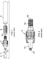
- the components of this product which is also known as a “fiber optic patch cord assembly”
- a contact ferrule 10 having first and second end faces 10a and 10b at respective opposed ferrule ends, with a cable passage (not shown) extending through the ferrule and opening into end faces 10a and 10b.
- a protective sleeve 12 is applied and a protective sleeve holder 14 is adapted to circumscribe sleeve 12.
- the further illustrated components include crimp sleeve 16 and protective heat-shrink tubing 18.
- the ferrule has front shell 10c and back shell 10d.
- a fiber optic cable is prepared by first inserting an end thereof through heat-shrink tubing 18 and crimp sleeve 16, both of which have interior diameters exceeding the outer diameter of the fiber optic cable. Insertion of the cable, so assembled with the tubing and crimp sleeve, into the ferrule passage is prefaced by removing a length of the fiber outer jacket to expose a length of the fiber buffer tubing and then by removing a length of the exposed buffer tubing to expose a length of the optical fiber itself.
- the cable is inserted into the passage, following removal of protective sleeve holder 14, typically with rotation of the cable until the outer jacket bottoms against the ferrule and the fibrous matter collects on the knurled outer surface of back shell 10d.
- Crimp sleeve 16 is now advanced until the same circumscribes the bottomed and collected outer jacket of the cable.
- Sleeve 16 is now crimped upon the fibrous matter and the cable.
- Heat-shrink tubing 18, which will constitute a strain relief boot upon application of heat thereto, is now advanced over the crimped sleeve, following application of a suitable epoxy to the interior thereof and onto the cable jacket, and is heat-shrunk.
- the optical fiber is scribed as close as possible to end face 10a and gently pulled until it breaks and the fiber end face is suitably polished.
- the product is seen as not maximizing strain relief, particularly in that crimping force providing strain relief is limited to the expanse of the fiber jacket collected on the knurled ferrule surface. Further, the product and practice are seen as requiring excess components, particularly, the heat-shrink tubing and as being labor-intensive in requiring the heat application step.
- the present invention has as its primary object the provision of fiber optic connectors of simplified structure and less labor-intensive in use.
- a specific object of the invention is the provision of improved crimp sleeves for fiber optic connectors.
- the invention provides, in one connector aspect thereof, a connector for a fiber optic cable of a type including a buffered optic fiber having an encircling jacket inclusive of fibrous matter, the connector including a back shell and a crimped body member having first and second open ends and defining a passage between the first and second open ends, the crimped member having first and second interior surfaces bounding the passage successively lengthwise of the body member, the first interior surface being in retentive engagement with exposed fibrous matter of the cable and in circumscribing relation to the back shell and the second interior surface being in retentive engagement with the jacket of the cable adjacent the exposed fibrous matter.
- the invention provides a connector for a fiber optic cable of a type including a buffered optic fiber having an encircling jacket inclusive of fibrous matter, the connector including a back shell and a crimped body member having first and second open ends and defining a passage between the first and second open ends, the crimped member having first, second and third interior surfaces bounding the passage successively lengthwise of the body member, the first interior surface extending from the first open end interiorly of the body member, the first interior surface being in retentive engagement with exposed fibrous matter of the cable and in circumscribing relation to the back shell, the second interior surface being in retentive engagement with the jacket of the cable adjacent said exposed fibrous matter and the third interior surface extending from the second open end interiorly of the body member and selectively engageable with the cable upon pulling of the cable transversely of the body member.
- the invention provides a crimp sleeve for connection of the back shell of a fiber optic cable connector with a fiber optic cable of a type including a buffered optic fiber having an encircling jacket inclusive of fibrous matter, the crimp sleeve including a crimpable body member having first and second open ends and defining a passage between the first and second open ends, the crimpable member having first and second interior surfaces bounding the passage successively lengthwise of the body member, the first interior surface extending from the first open end interiorly of the body member and having a first radius relative to a central axis of the body member, the second interior surface having a second radius relative to the central axis of the body member of measure less than the first radius, the first interior surface being adapted, upon crimping of the body member onto the cable, to retentively engage exposed fibrous matter of the cable and to circumscribe the back shell, the second interior surface being adapted, upon crimping of the
- the invention provides a crimp sleeve for connection of the back shell of a fiber optic cable connector with a fiber optic cable of a type including a buffered optic fiber having an encircling jacket inclusive of fibrous matter, the crimp sleeve including a crimpable body member having first and second open ends and defining a passage between the first and second open ends, the crimpable member having first, second and third interior surfaces bounding the passage successively lengthwise of the body member, the first interior surface extending from the first open end interiorly of the body member and having a first radius relative to a central axis of the body member, the second interior surface having a second radius relative to the central axis of the body member of measure less than the first radius, the third interior surface extending from the second open end interiorly of the body member and having radii relative to the central axis of the body member progressively therealong of measure successively exceeding the second radius, the first interior surface being adapted,
- Fig. 1 is an exploded view of a prior art fiber optic connector.
- Fig. 2 is a partly-broken away view of the ferrule of the Fig. 1 prior art connector.
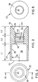
- Fig. 3 is a sectional view, as would be seen from plane III-III of Fig. 4 of a crimpable body member in accordance with the invention.
- Fig. 4 is a left side elevation of the Fig. 3 crimpable body member.
- Fig. 5 is a right side elevation of the Fig. 3 crimpable body member.
- Fig. 6 is a schematic illustration of cable preparation in accordance with the invention.
- Fig. 7 is an elevation, partly in section and partly broken away, depicting the crimpable body member of the invention in crimped assembly with a fiber optic cable and parent fiber optic connector structure.
- Fig. 8 is a right side elevation of Fig. 7.
- a crimp sleeve in accordance with the invention is comprised of a crimpable body member 20 having first and second open ends 22 and 24.
- a passage extends through body member 20 into communication with open ends 22 and 24 and has at least two diverse characteristics.
- passage part 26 is bounded by interior circular surface 28, which has a radius R1 with respect to body member central axis CA.
- passage part 30 is bounded by interior threaded surface 32, which has an interiormost radius R2, defined by the crests of the threading, of R2. As indicated in Fig. 3, radius R1 substantially exceeds that of radius R2.
- Body member 20 preferably further defines a third passage part 34, extending over length L3, and having an interior bounding surface 36 extending to second open end 24 interiorly of the body member and having radii relative to central axis CA progressively therealong of measure successively exceeding radius R2 and ultimately reaching substantially the radius of body member 20 at end 24.
- a fiber optic cable with body member 20 thereon has its jacket and buffer removed, as in the prior art practice, at its intended optical interface end. That portion of the cable to be ultimately resident interiorly of back shell 10d and in the passage part 26 extending over length L1, has the fibrous matter, typically Kelvar fibers, pulled outwardly of the cable to extend forwardly thereof. The cable jacketing adjacent the exposed fibrous matter is retained intact for ultimate residence in the passage part 30 extending over length L2.
- the cable, so prepared, is shown in part in the schematic showing of Fig. 6, wherein the jacketed fiber is indicated as 38, the buffered fiber as 40 and the exposed fibrous matter as 42.
- the cable is now inserted into the passage of ferrule 10 and the exposed fibrous matter is dressed onto the knurled surface of back shell 10d.
- Body member 20 is now advanced into circumscribing relation with the exposed fibrous matter and the knurled surface of back shell 10d and crimped thereon.
- Radius R1 of Fig. 3 is selected to accommodate passage of body member 20 onto the assembled fibrous matter and back shell 10d.
- Radius R2 of Fig. 3 is selected to accommodate passage of the body member onto the jacketed fiber.
- Radii of surface 36 are selected to maintain the surface free of engagement with the jacketed fiber distal from surface 32.
- body member 20 is shown in its crimped condition.
- Interior surface 28, as shown is adapted, upon crimping of the body member onto the cable, to retentively engage the fibrous matter 42 of the cable cooperatively with back shell 10d, which the body member circumscribes.
- Interior surface 32 is adapted, upon crimping of the body member onto the cable, itself to retentively engage the jacket of the cable.
- the third interior surface is used in the preferred embodiment of the invention, which affords benefit beyond that provided by an embodiment using only the first and second interior surfaces.
- surface 36 is normally unengaged with the cable, but is selectively engageable with the cable to lessen microbending loss upon pulling of the cable transversely of the crimpable member central axis.
- the second interior surface desirably includes radially interiorly directed means for enhancing retentive engagement of the jacket of the cable adjacent the exposed fibrous matter in the form of threading
- other means may be employed or such means may be omitted.
- the connector back shell desirably includes radially outwardly directed means for enhancing retentive engagement of the exposed fibrous matter in the form of knurling
- other means may be employed or such means may be omitted.
Landscapes
- Physics & Mathematics (AREA)
- General Physics & Mathematics (AREA)
- Optics & Photonics (AREA)
- Mechanical Coupling Of Light Guides (AREA)
- Medicines That Contain Protein Lipid Enzymes And Other Medicines (AREA)
Applications Claiming Priority (2)
| Application Number | Priority Date | Filing Date | Title |
|---|---|---|---|
| US991048 | 1992-12-15 | ||
| US07/991,048 US5317664A (en) | 1992-12-15 | 1992-12-15 | Fiber optic assembly and crimp sleeve used with the assembly |
Publications (3)
| Publication Number | Publication Date |
|---|---|
| EP0602958A2 true EP0602958A2 (fr) | 1994-06-22 |
| EP0602958A3 EP0602958A3 (fr) | 1995-06-14 |
| EP0602958B1 EP0602958B1 (fr) | 1999-03-17 |
Family
ID=25536804
Family Applications (1)
| Application Number | Title | Priority Date | Filing Date |
|---|---|---|---|
| EP93310140A Expired - Lifetime EP0602958B1 (fr) | 1992-12-15 | 1993-12-15 | Assemblage fibre-optique à manchon de sertissage |
Country Status (4)
| Country | Link |
|---|---|
| US (1) | US5317664A (fr) |
| EP (1) | EP0602958B1 (fr) |
| CA (1) | CA2111514A1 (fr) |
| DE (1) | DE69323968T2 (fr) |
Families Citing this family (19)
| Publication number | Priority date | Publication date | Assignee | Title |
|---|---|---|---|---|
| US5911248A (en) * | 1997-08-11 | 1999-06-15 | Dresser Industries, Inc. | Gasoline dispenser and cable assembly for preventing vapor flow |
| US6272273B1 (en) | 1999-09-02 | 2001-08-07 | Alcatel | Hermetic cable joint |
| US6390688B1 (en) | 2000-05-05 | 2002-05-21 | Hubbell Incorporated | Strain relief connector for fiber optic cable and method of making same |
| US6726373B2 (en) | 2000-05-05 | 2004-04-27 | Hubbell Incorporated | Strain relief connector for fiber optic cable and method of making same |
| US20020164130A1 (en) * | 2001-05-07 | 2002-11-07 | Elkins Robert B. | Fiber optic module attachment including a fiber locating connector |
| US20050041926A1 (en) * | 2001-05-07 | 2005-02-24 | Elkins Robert B. | Panel assembly with dense fiber output array |
| US6536956B2 (en) * | 2001-07-26 | 2003-03-25 | Corning Cable Systems Llc | Ferrule boot for optical connectors |
| USD476957S1 (en) | 2002-03-01 | 2003-07-08 | Nuvisions International, Inc. | Fiber coupling device |
| USD593947S1 (en) * | 2008-08-26 | 2009-06-09 | Jin-I Wang | Transmission signal connector |
| US7722416B2 (en) * | 2008-10-02 | 2010-05-25 | Delphi Technologies, Inc. | Electrical connection system for use on aluminum wires |
| US7778511B1 (en) * | 2009-06-17 | 2010-08-17 | Ofs Fitel Llc | Optical fiber cables |
| US8523590B2 (en) | 2011-07-29 | 2013-09-03 | General Electric Company | Cable system and methods of assembling a cable system |
| US9759288B2 (en) * | 2013-04-04 | 2017-09-12 | The National Telephone Supply Company | Crimp sleeve |
| US9429732B2 (en) | 2013-05-03 | 2016-08-30 | Corning Cable Systems Llc | Fiber optic cable crimp assemblies employing integrally connected cable strain relief boots, and related fiber optic connectors, cables, and methods |
| WO2015008668A1 (fr) * | 2013-07-18 | 2015-01-22 | 株式会社クラレ | Membrane en fibre creuse poreuse rendue hydrophile à base de fluorure de vinylidène et procédé de fabrication associé |
| US9551842B2 (en) | 2015-01-15 | 2017-01-24 | Corning Optical Communications LLC | Fiber optic connector with strain relief assembly |
| USD780136S1 (en) | 2015-05-05 | 2017-02-28 | Nu Visions International, Inc. | Hard case for fiber optic test equipment |
| DE102015108088A1 (de) * | 2015-05-21 | 2016-11-24 | Amad Mennekes Holding Gmbh & Co. Kg | Kontakthülse für Steckvorrichtungen |
| CN209028258U (zh) | 2016-03-17 | 2019-06-25 | 康宁光电通信有限责任公司 | 可调谐光纤连接器、连接器子组件、电缆组件和子组件 |
Family Cites Families (25)
| Publication number | Priority date | Publication date | Assignee | Title |
|---|---|---|---|---|
| US2468169A (en) * | 1942-09-25 | 1949-04-26 | Aircraft Marine Prod Inc | Method of making electrical connectors |
| GB561859A (en) * | 1943-01-25 | 1944-06-07 | Copper Dev Ass | Improved method of and means for connecting overhead transmission lines and the like |
| US2672596A (en) * | 1949-11-03 | 1954-03-16 | Theodore J Grypma | Compressible cable connector |
| US3033600A (en) * | 1960-05-04 | 1962-05-08 | Drysdale John | Connectors for jointing wires, rods and the like |
| GB954409A (en) * | 1962-01-09 | 1964-04-08 | Cable Covers Ltd | Compression connectors for joining or terminating wires, rods and other suitable members |
| CA965169A (en) * | 1970-11-09 | 1975-03-25 | Lawrence J. Kehl | Electrical contact and conductor, and method of making |
| US4148557A (en) * | 1977-07-11 | 1979-04-10 | Hewlett-Packard Company | Adjustable fiber optic connector |
| DE2943180C2 (de) * | 1979-10-25 | 1986-04-24 | Bunker Ramo Corp., Oak Brook, Ill. | Lichtleiter-Steckverbinder |
| US4440469A (en) * | 1980-09-18 | 1984-04-03 | Amp Incorporated | Optical waveguide connector |
| US4447121A (en) * | 1981-11-06 | 1984-05-08 | Amp Incorporated | Connector for fiber optic member |
| EP0130513A3 (fr) * | 1983-06-26 | 1986-12-30 | Allied Corporation | Connecteur pour fibre optique |
| US4679895A (en) * | 1984-08-31 | 1987-07-14 | Amp Incorporated | Adhesiveless optical fiber connector |
| US4693550A (en) * | 1985-03-11 | 1987-09-15 | Methode Electronics, Inc. | Crimp type fiber optic connector |
| US4938558A (en) * | 1989-03-09 | 1990-07-03 | Amp Incorporated | Fused connector for optical fiber |
| GB2229829B (en) * | 1989-03-31 | 1993-03-17 | Philips Nv | A connector for a fibre optic cable |
| US4961624A (en) * | 1989-08-29 | 1990-10-09 | Amp Incorporated | Optical fiber termination with crimping body |
| US5013122A (en) * | 1989-08-29 | 1991-05-07 | Amp Incorporated | Threaded crimping body for fiber optic termination |
| US5142602A (en) * | 1989-09-05 | 1992-08-25 | Labinal Components & Systems, Inc. | Fiber optic connectors |
| US5142601A (en) * | 1990-06-21 | 1992-08-25 | The Furukawa Electric Co., Ltd. | Optical connector and a method for assembling the same |
| US5062683A (en) * | 1990-07-09 | 1991-11-05 | Molex Incorporated | Strain relief connector for optical fiber |
| US5101463A (en) * | 1991-05-03 | 1992-03-31 | Minnesota Mining And Manufacturing Company | Push-pull optical fiber connector |
| US5140661A (en) * | 1991-08-06 | 1992-08-18 | G & H Technology, Inc. | Optical fiber terminus |
| US5222169A (en) * | 1992-02-18 | 1993-06-22 | Foxconn International, Inc. | Optical fiber connector assembly |
| US5202942A (en) * | 1992-04-03 | 1993-04-13 | Amp Incorporated | Cable termination member for fiber optic connectors having improved strain relief |
| US5224187A (en) * | 1992-04-29 | 1993-06-29 | Scientific-Atlanta, Inc. | Fiber optic cable connectors providing strain relief |
-
1992
- 1992-12-15 US US07/991,048 patent/US5317664A/en not_active Expired - Fee Related
-
1993
- 1993-12-15 CA CA002111514A patent/CA2111514A1/fr not_active Abandoned
- 1993-12-15 DE DE69323968T patent/DE69323968T2/de not_active Expired - Fee Related
- 1993-12-15 EP EP93310140A patent/EP0602958B1/fr not_active Expired - Lifetime
Also Published As
| Publication number | Publication date |
|---|---|
| EP0602958A3 (fr) | 1995-06-14 |
| US5317664A (en) | 1994-05-31 |
| EP0602958B1 (fr) | 1999-03-17 |
| DE69323968D1 (de) | 1999-04-22 |
| DE69323968T2 (de) | 1999-07-29 |
| CA2111514A1 (fr) | 1994-06-16 |
Similar Documents
| Publication | Publication Date | Title |
|---|---|---|
| US5317664A (en) | Fiber optic assembly and crimp sleeve used with the assembly | |
| US4336977A (en) | Crimped connector assembly for fiber optic cables | |
| US4648688A (en) | Connector for fiber optic member including polishing fixture and method of terminating same | |
| US10782489B2 (en) | Fiber optic connector | |
| US4773725A (en) | Termination of a fiber optic transmission member and method therefore | |
| CA1043604A (fr) | Faisceau de fibres optiques | |
| EP1245980B1 (fr) | Trousse de bifurcation pour câble optique | |
| US6909828B2 (en) | Fiberoptic furcation device with crimp | |
| US5396572A (en) | Optical fiber connector having a unipartite cap | |
| US6899467B2 (en) | Fiber optic plug and receptacle assembly | |
| CA1187317A (fr) | Collier de serrage pour cable a fibres optiques | |
| US4693550A (en) | Crimp type fiber optic connector | |
| CA1158900A (fr) | Connecteur pour le raccordement aboute de deux fibres optiques | |
| JPH0682657A (ja) | 光ファイバケーブルと光ファイバ用雄雌共用コネクタ | |
| US5140662A (en) | Method of assembling connector and cable | |
| EP0061243B1 (fr) | Connecteur pour guide d'ondes optiques | |
| JPH07218764A (ja) | 光ファイバーコネクタ | |
| WO2001042836A2 (fr) | Connecteur a fibres optiques et procede de montage y relatif | |
| CN101872045A (zh) | 分叉体及利用该分叉体的光纤组件 | |
| EP0192735A1 (fr) | Connecteur pour fibre optique. | |
| US5425119A (en) | Connector strain relief for optical fiber | |
| US12411288B2 (en) | Fiber optic connector having flattened regions that face and align to prevent rotation | |
| KR20030060061A (ko) | 콘투어링된 내부 스터브 크림프 백본 | |
| WO1995007479A1 (fr) | Connecteur a fiches | |
| US5062683A (en) | Strain relief connector for optical fiber |
Legal Events
| Date | Code | Title | Description |
|---|---|---|---|
| PUAI | Public reference made under article 153(3) epc to a published international application that has entered the european phase |
Free format text: ORIGINAL CODE: 0009012 |
|
| AK | Designated contracting states |
Kind code of ref document: A2 Designated state(s): BE CH DE ES FR GB IT LI LU NL SE |
|
| PUAL | Search report despatched |
Free format text: ORIGINAL CODE: 0009013 |
|
| AK | Designated contracting states |
Kind code of ref document: A3 Designated state(s): BE CH DE ES FR GB IT LI LU NL SE |
|
| 17P | Request for examination filed |
Effective date: 19951120 |
|
| GRAG | Despatch of communication of intention to grant |
Free format text: ORIGINAL CODE: EPIDOS AGRA |
|
| 17Q | First examination report despatched |
Effective date: 19980504 |
|
| GRAG | Despatch of communication of intention to grant |
Free format text: ORIGINAL CODE: EPIDOS AGRA |
|
| GRAH | Despatch of communication of intention to grant a patent |
Free format text: ORIGINAL CODE: EPIDOS IGRA |
|
| GRAH | Despatch of communication of intention to grant a patent |
Free format text: ORIGINAL CODE: EPIDOS IGRA |
|
| GRAA | (expected) grant |
Free format text: ORIGINAL CODE: 0009210 |
|
| RAP1 | Party data changed (applicant data changed or rights of an application transferred) |
Owner name: THOMAS & BETTS CORPORATION (A TENNESSEE CORPORATIO |
|
| AK | Designated contracting states |
Kind code of ref document: B1 Designated state(s): BE CH DE ES FR GB IT LI LU NL SE |
|
| PG25 | Lapsed in a contracting state [announced via postgrant information from national office to epo] |
Ref country code: SE Free format text: THE PATENT HAS BEEN ANNULLED BY A DECISION OF A NATIONAL AUTHORITY Effective date: 19990317 Ref country code: NL Free format text: LAPSE BECAUSE OF FAILURE TO SUBMIT A TRANSLATION OF THE DESCRIPTION OR TO PAY THE FEE WITHIN THE PRESCRIBED TIME-LIMIT Effective date: 19990317 Ref country code: LI Free format text: LAPSE BECAUSE OF FAILURE TO SUBMIT A TRANSLATION OF THE DESCRIPTION OR TO PAY THE FEE WITHIN THE PRESCRIBED TIME-LIMIT Effective date: 19990317 Ref country code: FR Free format text: LAPSE BECAUSE OF FAILURE TO SUBMIT A TRANSLATION OF THE DESCRIPTION OR TO PAY THE FEE WITHIN THE PRESCRIBED TIME-LIMIT Effective date: 19990317 Ref country code: ES Free format text: THE PATENT HAS BEEN ANNULLED BY A DECISION OF A NATIONAL AUTHORITY Effective date: 19990317 Ref country code: CH Free format text: LAPSE BECAUSE OF FAILURE TO SUBMIT A TRANSLATION OF THE DESCRIPTION OR TO PAY THE FEE WITHIN THE PRESCRIBED TIME-LIMIT Effective date: 19990317 Ref country code: BE Free format text: LAPSE BECAUSE OF FAILURE TO SUBMIT A TRANSLATION OF THE DESCRIPTION OR TO PAY THE FEE WITHIN THE PRESCRIBED TIME-LIMIT Effective date: 19990317 |
|
| REG | Reference to a national code |
Ref country code: CH Ref legal event code: EP |
|
| REF | Corresponds to: |
Ref document number: 69323968 Country of ref document: DE Date of ref document: 19990422 |
|
| NLV1 | Nl: lapsed or annulled due to failure to fulfill the requirements of art. 29p and 29m of the patents act | ||
| EN | Fr: translation not filed | ||
| REG | Reference to a national code |
Ref country code: CH Ref legal event code: PL |
|
| PG25 | Lapsed in a contracting state [announced via postgrant information from national office to epo] |
Ref country code: LU Free format text: LAPSE BECAUSE OF NON-PAYMENT OF DUE FEES Effective date: 19991215 |
|
| PLBE | No opposition filed within time limit |
Free format text: ORIGINAL CODE: 0009261 |
|
| STAA | Information on the status of an ep patent application or granted ep patent |
Free format text: STATUS: NO OPPOSITION FILED WITHIN TIME LIMIT |
|
| 26N | No opposition filed | ||
| PGFP | Annual fee paid to national office [announced via postgrant information from national office to epo] |
Ref country code: DE Payment date: 20001122 Year of fee payment: 8 |
|
| REG | Reference to a national code |
Ref country code: GB Ref legal event code: IF02 |
|
| PGFP | Annual fee paid to national office [announced via postgrant information from national office to epo] |
Ref country code: GB Payment date: 20020206 Year of fee payment: 9 |
|
| PG25 | Lapsed in a contracting state [announced via postgrant information from national office to epo] |
Ref country code: DE Free format text: LAPSE BECAUSE OF NON-PAYMENT OF DUE FEES Effective date: 20020702 |
|
| PG25 | Lapsed in a contracting state [announced via postgrant information from national office to epo] |
Ref country code: GB Free format text: LAPSE BECAUSE OF NON-PAYMENT OF DUE FEES Effective date: 20021215 |
|
| GBPC | Gb: european patent ceased through non-payment of renewal fee |
Effective date: 20021215 |
|
| PG25 | Lapsed in a contracting state [announced via postgrant information from national office to epo] |
Ref country code: IT Free format text: LAPSE BECAUSE OF NON-PAYMENT OF DUE FEES;WARNING: LAPSES OF ITALIAN PATENTS WITH EFFECTIVE DATE BEFORE 2007 MAY HAVE OCCURRED AT ANY TIME BEFORE 2007. THE CORRECT EFFECTIVE DATE MAY BE DIFFERENT FROM THE ONE RECORDED. Effective date: 20051215 |