EP0602959A1 - Dispositif de signalisation de passage bidirectionnel d'un racleur dans un pipe-line - Google Patents
Dispositif de signalisation de passage bidirectionnel d'un racleur dans un pipe-line Download PDFInfo
- Publication number
- EP0602959A1 EP0602959A1 EP93310141A EP93310141A EP0602959A1 EP 0602959 A1 EP0602959 A1 EP 0602959A1 EP 93310141 A EP93310141 A EP 93310141A EP 93310141 A EP93310141 A EP 93310141A EP 0602959 A1 EP0602959 A1 EP 0602959A1
- Authority
- EP
- European Patent Office
- Prior art keywords
- magnetic
- ball
- plunger
- pipeline
- indicator ball
- Prior art date
- Legal status (The legal status is an assumption and is not a legal conclusion. Google has not performed a legal analysis and makes no representation as to the accuracy of the status listed.)
- Granted
Links
- 230000011664 signaling Effects 0.000 title claims abstract description 20
- 230000002457 bidirectional effect Effects 0.000 title description 4
- 210000002445 nipple Anatomy 0.000 claims abstract description 20
- 238000013459 approach Methods 0.000 claims abstract description 5
- 239000000696 magnetic material Substances 0.000 claims description 7
- 238000007789 sealing Methods 0.000 claims description 6
- 230000000717 retained effect Effects 0.000 claims 1
- 239000000428 dust Substances 0.000 abstract description 13
- 239000000463 material Substances 0.000 description 8
- 230000000007 visual effect Effects 0.000 description 4
- RWSOTUBLDIXVET-UHFFFAOYSA-N Dihydrogen sulfide Chemical compound S RWSOTUBLDIXVET-UHFFFAOYSA-N 0.000 description 1
- 241001147416 Ursus maritimus Species 0.000 description 1
- 238000004140 cleaning Methods 0.000 description 1
- 239000003086 colorant Substances 0.000 description 1
- 238000010276 construction Methods 0.000 description 1
- 238000013507 mapping Methods 0.000 description 1
- 238000000034 method Methods 0.000 description 1
- 230000001960 triggered effect Effects 0.000 description 1
Images
Classifications
-
- G—PHYSICS
- G01—MEASURING; TESTING
- G01D—MEASURING NOT SPECIALLY ADAPTED FOR A SPECIFIC VARIABLE; ARRANGEMENTS FOR MEASURING TWO OR MORE VARIABLES NOT COVERED IN A SINGLE OTHER SUBCLASS; TARIFF METERING APPARATUS; MEASURING OR TESTING NOT OTHERWISE PROVIDED FOR
- G01D5/00—Mechanical means for transferring the output of a sensing member; Means for converting the output of a sensing member to another variable where the form or nature of the sensing member does not constrain the means for converting; Transducers not specially adapted for a specific variable
- G01D5/02—Mechanical means for transferring the output of a sensing member; Means for converting the output of a sensing member to another variable where the form or nature of the sensing member does not constrain the means for converting; Transducers not specially adapted for a specific variable using mechanical means
- G01D5/06—Mechanical means for transferring the output of a sensing member; Means for converting the output of a sensing member to another variable where the form or nature of the sensing member does not constrain the means for converting; Transducers not specially adapted for a specific variable using mechanical means acting through a wall or enclosure, e.g. by bellows, by magnetic coupling
-
- F—MECHANICAL ENGINEERING; LIGHTING; HEATING; WEAPONS; BLASTING
- F16—ENGINEERING ELEMENTS AND UNITS; GENERAL MEASURES FOR PRODUCING AND MAINTAINING EFFECTIVE FUNCTIONING OF MACHINES OR INSTALLATIONS; THERMAL INSULATION IN GENERAL
- F16L—PIPES; JOINTS OR FITTINGS FOR PIPES; SUPPORTS FOR PIPES, CABLES OR PROTECTIVE TUBING; MEANS FOR THERMAL INSULATION IN GENERAL
- F16L55/00—Devices or appurtenances for use in, or in connection with, pipes or pipe systems
- F16L55/26—Pigs or moles, i.e. devices movable in a pipe or conduit with or without self-contained propulsion means
- F16L55/48—Indicating the position of the pig or mole in the pipe or conduit
Definitions
- the present invention relates to a device for detecting and signaling the passage of a pig past a point in a pipeline. More specifically, the present invention relates to a device employing a magnetic field to initiate either a visual or an electronic signal to indicate passage of the pig.
- a movable plug or a pig within a pipeline either to travel between and separate different products as they flow consecutively through a single pipeline or to travel through the pipeline in order to service it by cleaning it, mapping it, etc.
- a pig Whenever a pig is being used, it is necessary to be able to detect its location.
- One way this is done is to utilize a device which remains stationary relative to the pipeline and is provided with means for detecting and signaling passage of the pig past the device.
- Previous devices for detecting and signaling passage of a pig can be categorized as one of two general types.
- the first type as exemplified by U.S. Patent No. 3,109,410 issued on November 5, 1963 to inventor Burton Ver Nooy, employs a trigger mechanism internally disposed within the pipeline which is physically tripped by passage of a pig. The physical movement of the trigger is transmitted by a variety of gears or other types of mechanical means through a sealing mechanism in an enclosure of the device to a signaling device located exterior to the enclosure.
- the second type of device for detecting and signaling passage of a pig is represented by U.S. Patent No. 4,638,278 issued on January 20, 1987 to inventor Mark E.Bullock.
- This second type of device employs a specially designed pig, usually one to which magnets have been attached.
- This special pig is magnetically detected by a sensing unit located external to the pipeline.
- the sensing unit normally employs a magnetically triggered switch which can be used to operate a signaling device.
- the pig must be constructed of a magnetically detectable material or must be retrofitted with magnetically detectable material, such as magnets, in order for the sensing unit to detect its passage.
- magnetically detectable material such as magnets
- the present invention addresses these problems by providing a device which combines the reliability of mechanical triggering with the non-intrusiveness of magnetic sensing.
- the present invention utilizes an enclosed and sealed trigger mechanism provided with a polar magnet on its upper end and provided with an actuator on its lower end which extends down into the pipeline.
- a passing pig engages the actuator, causing the trigger mechanism and the attached polar magnet to move upward where a magnetic field associated with the polar magnet passes through a sealed enclosure housing the trigger mechanism and can either activate a visual signal device or, optionally, can activate a proximity switch.
- the present invention is a signaling device which attaches to a pipeline by means of a hollow nipple which is welded to the pipeline and which opens to an interior of the pipeline.
- a plug assembly having a closed upper end and an open lower end, screws into the nipple and seals with the nipple by means of an O-ring provided in a groove extending around the plug assembly.
- a chamber is provided within the plug assembly and opens downward into the pipeline at the plug assembly lower end.
- the chamber contains a movable plunger having a cylindrical polar magnet at its upper magnetic end and an actuator attached at its lower actuator end. The actuator attaches by means of a pin so that the actuator extends down into the pipeline when the plunger is in its lower position.
- a spring encircles the plunger, with one end of the spring abutting a retainer toroid and the other end abutting a seal adjacent the plunger's lower actuator end.
- the retainer toroid is positioned in the chamber so that it encircles the plunger's upper magnetic end when the plunger is in its lower position.
- a cap assembly screws onto the nipple and is provided with a clear convex shaped dust cover through which a person can view into an internal cavity provided in the cap assembly.
- a magnetic indicator ball rotatably mounts inside the internal cavity by means of a lever arm which attaches to one side of the ball and movably extends through an opening in the cap assembly, terminating at a reset lever, and by means of an ear which attaches to an opposite side of the ball and movably extends through a second opening in the cap assembly.
- First and second polar ball magnets are located opposite each other on the ball, and a bar of magnetic material extends through the ball and abuts against the polar ball magnets.
- the first and second polar ball magnets are oriented perpendicular to the ear and lever arm, and like poles of the first and second polar ball magnets are aligned in the same direction. Also, the ball magnets are oriented so that the magnetic pole which faces outward from the ball on the first polar ball magnet is of the same polarity as the cylindrical polar magnet, and the magnetic pole which faces outward from the ball on the second polar ball magnet is of opposite polarity to the cylindrical polar magnet.
- the upper end of the plug assembly is provided with an area of magnetic material which attracts whichever polar ball magnet is closest to it, thus, discouraging rotation of the ball.
- a lower half of the ball is colored yellow and an upper half of the ball is colored black so that the intersection of the two halves forms a diameter which intersects the ear and the lever arm and is perpendicular to the bar and polar ball magnets.
- the ball is set by means of the reset lever so that the black upper half of the ball is visible through the dust cover.
- the actuator As a pig travels through the pipeline it forces the actuator upward, causing the plunger to travel upward until it reaches its most upward position and causing the cylindrical polar magnet to be moved upward out of the magnetic influence of the retainer toroid.
- a magnetic field associated with the cylindrical polar magnet repels the first polar ball magnet, causing the ball to rotate 180 degrees so that the yellow lower half is visible through the dust cover.
- the plunger returns to its original lower position by means of force exerted on it by the spring, but the ball will remain with the lower yellow half visible through the dust cover until reset by means of the reset lever.
- a proximity switch an electrical switch which is activated in response to the magnetic field of the cylindrical polar magnet, can be substituted instead of the ball to provide an electrical, rather than a visual, indication of the passage of a pig through the pipeline.
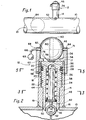
- Figure 1 is a diagrammatic side elevation of a pipeline to which is attached a bidirectional pipeline pig signaling device constructed according to a preferred embodiment of the present invention.
- Figure 2 is an enlarged cut-away side elevation of the signaling device of Figure 1.
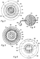
- Figure 3 is a cross-sectional view taken along line 3-3 of Figure 2.
- Figure 4 is a cross-sectional side elevation of the magnetic ball indicator with the reset lever attached.
- Figure 5 is a cross-sectional view taken along line 5-5 of Figure 2.
- Figure 6 is a bottom elevation of the signaling device taken along line 6-6 of Figure 2.
- FIG. 1 there is illustrated a pipeline 10 to which a bidirectional pipeline pig signaling device 12 is attached.
- Figure 2 shows a hollow nipple 14 for the signaling device 12 attaching to the pipeline 10 by means of a weld 16 or other suitable attachment means.
- the nipple 14 has an upper open end 17 extending upward perpendicularly to the pipeline 10 and has an opposite lower open end 19 which is welded to the pipeline 10 and which communicates with an internal area 21 of the pipeline 10.
- the nipple 14 is provided with female nipple threads 18 and with male nipple threads 20.
- the female nipple threads 18 engage with male plug assembly threads 22 provided on a plug assembly 24 located within the nipple 14 to secure the plug assembly 24 to the nipple 14.
- a groove 26 is provided around the plug assembly 24 and located above the male plug assembly threads 22.
- an O-ring 28 is held in the groove 26 by means of a retainer ring 29 as a means to seal between the nipple 14 and the plug assembly 24.
- the O-ring 28 which seals between the nipple 14 and the plug assembly 24 is capable of withstanding high pressures such as those encountered within the pipeline 10.
- the plug assembly 24 has an internal chamber 30 which opens downward at a lower end 32 of the plug assembly 24, with an upper end 34 of the plug assembly forming a closed ceiling 36 over the chamber 30.
- a plunger 38 is movably provided within the chamber 30.
- the plunger 38 is provided with an upper magnetic end 40, which is located adjacent the ceiling 36, and a lower actuator end 42 extending downward toward the pipeline 10.
- the upper magnetic end 40 is provided with a small cylindrical polar magnet 45.
- a retainer toroid 44 is provided in the chamber 30 so that it encircles the magnetic end 40 of the plunger 38 when the plunger is in the lower position, as illustrated in Figure 2.
- the retainer toroid 44 is constructed of a magnetic material and serves to keep a magnetic field (not illustrated) associated with the cylindrical polar magnet 45 from reaching upward to a magnetic indicator ball 46, which will be hereinafter described.
- a spring 48 encircles the plunger 38 and extends upward to the retainer toroid 44 and downward to a seal 50 provided on the plunger 38 adjacent the actuator end 42. As best seen in Figure 3, the spring 48 is movably located within the chamber 30 and between the plunger 38 and the plug assembly 24.
- the actuator end 42 of the plunger 38 is provided with an actuator 52 which is secured to the plunger 38 by means of a pin 54.
- the pin 54 also prevents the plunger 38 from being pushed by the spring 48 out of the chamber 30 and into the internal area 21 of the pipeline 10.
- the actuator 52 extends beyond the lower end 32 of the plug assembly 24 and into the internal area 21 of the pipeline 10.
- a cap assembly 56 secures to the nipple 14 by means of female cap assembly threads 58 provided on the cap assembly 56 which engage the male nipple threads 20.
- the cap assembly 56 is provided with a clear convex or dome-shaped dust cover 60 through which a person (not shown) can look to view inside an internal cavity 62 which is provided within the cap assembly 56.
- the magnetic indicator ball 46 is rotatably mounted within the internal cavity 62 so that an upward facing half of the magnetic indicator ball 46 is visible to a person (not shown) via the dust cover 60.
- the magnetic indicator ball 46 rotatably mounts within the internal cavity 62 on an attached ear 64 secured to one side of the magnetic indicating ball 46 and on a lever arm 66 secured to an opposite side of the magnetic indicator ball 46.
- the lever arm 66 rotatably extends through an opening 68 provided in the dust cover 60 and terminates at a reset level 69.
- the ear 64 rotatably extends through a second opening 71 provided in the dust
- the magnetic indicator ball 46 is preferably made of a material having a low mass, such as plastic, in order that the magnetic indicator ball 46 can be rotated easily.
- the magnetic indicator ball 46 is provided with first and second polar ball magnets 70 and 72 located opposite each other on the magnetic indicator ball 46 and perpendicular to the ear 64 and the lever arm 66.
- the polar ball magnets 70 and 72 have their poles oriented in the same direction, with one pole of the first polar ball magnet 70 facing outward on the magnetic indicator ball 46 and an opposite pole of the second polar ball magnet 72 facing outward on the magnetic indicator ball 46 at a location 180 degrees from the first polar ball magnet 70.
- a magnetic field (not illustrated) associated with the cylindrical polar magnet 45 is of like polarity to an outward facing pole of the first polar ball magnet 70 and of opposite polarity to an outward facing pole of the second polar ball magnet 72.
- a bar 74 composed of highly magnetic material extends through the magnetic indicator ball 46 and between inward facing poles of the polar ball magnets 70 and 72.
- the upper end 34 of the plug assembly 24 is provided with an area 76 consisting of magnetic material which is attracted to whichever polar ball magnet, 70 or 72, is located proximal to it and, thus, tends to discourage rotation of the magnetic indicator ball 46 by holding the magnetic indicator ball 46 so that one of the polar ball magnets, either 70 or 72, is oriented downward and one of the polar ball magnets, either 72 or 70, is oriented upward.
- a lower half 78 of the magnetic indicator ball 46 is preferably bright fluorescent yellow in coloration and an upper half 80 of the magnetic indicator ball 46 is preferably black in coloration so that an interface 82 formed between the lower half 78 and the upper half 80 forms a diameter around the magnetic indicator ball 46 which intersects with the ear 64 and the lever arm 66 and which is perpendicular to the bar 74 connecting polar ball magnets 70 and 72 and perpendicular to the polar bar magnets 70 and 72.
- the colors or patterns of the lower half 78 and upper half 80 may vary so long as the lower half 78 is visually distinct from the upper half 80.
- the bidirectional signaling device 12 is set by means of the reset lever 69 so the black upper half 80 is visible through the dust cover 20.
- the actuator 52 initially extends downward into the pipeline 10 as shown in Figures 1 and 2.
- the spring 48 serves to maintain the plunger 38 in its lower position until a pig 84 traveling through the pipeline 10 encounters the actuator 52, forcing it upward.
- the actuator 52 is designed to be forced upward regardless of which direction the pig is traveling through the pipeline 10. Upward movement of the actuator 52, in turn, forces the plunger 38 to an upward position (not illustrated) in which the cylindrical polar magnet 45 moves upward in the chamber 30 with the plunger 38 until the cylindrical polar magnet 45 abuts the ceiling 36.
- the plunger 38 is held in its upward position by means of hydraulic pressure for a brief period of time after the pig 84 passes beyond the actuator 52 before it is forced back down to its lower position by the spring 48.
- the cylindrical polar magnet 45 moves out of the magnetic influence of the retainer toroid 44 and the magnetic field (not illustrated) associated with the cylindrical polar magnet 45 extends upward to the magnetic indicator ball 46.
- the first ball magnet 70 is repelled when the plunger 38 is in its upward position. This repulsive force causes the magnetic indicator ball 46 to rotate until the first polar ball magnet 70 is oriented upward and the second polar ball magnet 72 is oriented downward. At this point, because the outward facing pole of the second polar ball magnet 72 is opposite in polarity to the magnetic field associated with the cylindrical polar magnet 45, the second polar ball magnet 72 is held in a downward oriented position by the cylindrical polar magnet 45 while the plunger 38 remains in its upward position.
- the plunger 38 After the pig 84 has passed the device 12, the plunger 38 returns, under force exerted by the spring 48, to its initial lower position. But even after the cylindrical polar magnet 46 is lowered so it is again encircled by the retainer toroid 44 and its magnetic field no longer reaches the second polar ball magnet 72, attraction of the second polar ball magnet 72 to the area 76 prevents the magnetic indicator ball 46 from rotating back to its original position, ie. with the black colored upper half 80 visible through the dust cover 20.
- the cap assembly 56 can be modified to provide an electrical, rather than a visual, indication of the passage of the pig 84.
- the magnetic indicator ball 46 is replaced with a proximity switch (not illustrated) which is a magnetically activated electronic switch and the area 76 is eliminated.
- the proximity switch can be used to operate recording devices (not illustrated) located at either the signaling device 12 or located remotely. The recording devices may be selected from many different types of recorders, signals, etc.
Landscapes
- Engineering & Computer Science (AREA)
- General Engineering & Computer Science (AREA)
- Chemical & Material Sciences (AREA)
- Combustion & Propulsion (AREA)
- Mechanical Engineering (AREA)
- Physics & Mathematics (AREA)
- General Physics & Mathematics (AREA)
- Geophysics And Detection Of Objects (AREA)
- Coating Apparatus (AREA)
- Cleaning In General (AREA)
Applications Claiming Priority (2)
| Application Number | Priority Date | Filing Date | Title |
|---|---|---|---|
| US07/991,197 US5279251A (en) | 1992-12-16 | 1992-12-16 | Bidirectional pipeline pig signaling device |
| US991197 | 1992-12-16 |
Publications (2)
| Publication Number | Publication Date |
|---|---|
| EP0602959A1 true EP0602959A1 (fr) | 1994-06-22 |
| EP0602959B1 EP0602959B1 (fr) | 1997-01-29 |
Family
ID=25536972
Family Applications (1)
| Application Number | Title | Priority Date | Filing Date |
|---|---|---|---|
| EP93310141A Expired - Lifetime EP0602959B1 (fr) | 1992-12-16 | 1993-12-15 | Dispositif de signalisation de passage bidirectionnel d'un racleur dans un pipe-line |
Country Status (5)
| Country | Link |
|---|---|
| US (1) | US5279251A (fr) |
| EP (1) | EP0602959B1 (fr) |
| DE (1) | DE69307853T2 (fr) |
| DK (1) | DK0602959T3 (fr) |
| ES (1) | ES2101250T3 (fr) |
Families Citing this family (7)
| Publication number | Priority date | Publication date | Assignee | Title |
|---|---|---|---|---|
| US5506505A (en) * | 1994-05-09 | 1996-04-09 | Tdw Delaware, Inc. | Apparatus for remotely indicating pipeline pig including a sensor housing having surface engaging orthogonally disposed paramagnetic materials a solid state sensor and a flag |
| US6357384B1 (en) | 2000-03-20 | 2002-03-19 | Dwane O. Laymon | Pig detector |
| US20040211443A1 (en) * | 2002-03-19 | 2004-10-28 | Frank's Casing Crew And Rental Tools, Inc. | Magnetic plug detector |
| US6823751B1 (en) * | 2002-05-22 | 2004-11-30 | Meter Engineers, Inc. | Sphere or pig detection switch assembly |
| US7861665B2 (en) * | 2007-05-11 | 2011-01-04 | Tdw Delaware Inc. | Pipeline pig signal with adjustable mounting |
| BRPI0900683A2 (pt) * | 2009-03-17 | 2010-12-14 | Aselco Indestria Com Imp Acco E Exportacco De Instr Ltda | dispositivo de detecÇço e de sinalizaÇço de passagem de pig ou esfera e conjunto de detecÇço e sinalizaÇço de passagem de pig ou esfera |
| US9248477B2 (en) | 2012-11-06 | 2016-02-02 | Tdw Delaware, Inc. | Pipeline pig signal trigger cavity seal |
Citations (5)
| Publication number | Priority date | Publication date | Assignee | Title |
|---|---|---|---|---|
| FR1233685A (fr) * | 1959-05-06 | 1960-10-12 | Transport Petrol Par Pipeline | Dispositif de signalisation pour canalisations de transport de fluides |
| US3109410A (en) * | 1959-12-24 | 1963-11-05 | Williamson Inc T | Passage indicator for pipeline scrapers and the like |
| US4491018A (en) * | 1983-06-17 | 1985-01-01 | F. H. Maloney Company | Pig detector |
| US4638278A (en) * | 1986-01-14 | 1987-01-20 | Halliburton Company | Magnetic detector apparatus |
| EP0254503A2 (fr) * | 1986-07-23 | 1988-01-27 | PIPELINE ENGINEERING & SUPPLY CO. LTD. | Dispositif de signalisation d'un racleur |
Family Cites Families (8)
| Publication number | Priority date | Publication date | Assignee | Title |
|---|---|---|---|---|
| US3327677A (en) * | 1966-06-16 | 1967-06-27 | William R King | Pipeline pig signalling device |
| FR1492312A (fr) * | 1966-07-08 | 1967-08-18 | Dowty Electrics Ltd | Indicateur actionné électriquement |
| US3646906A (en) * | 1968-02-01 | 1972-03-07 | Purolator Products Inc | Pressure indicator and surge control device |
| GB1407815A (en) * | 1972-05-12 | 1975-09-24 | Pipeline Eng Supply Co Ltd | Signalling devices |
| US3815542A (en) * | 1972-07-27 | 1974-06-11 | Pall Corp | Magnetic pressure indicator |
| GB2107063B (en) * | 1981-09-23 | 1985-09-11 | British Gas Corp | Fixing geographical reference of pipeline pigs in pipelines |
| US4596204A (en) * | 1983-08-15 | 1986-06-24 | T. D. Williamson, Inc. | Flag-type pig-sig |
| US4714888A (en) * | 1984-06-11 | 1987-12-22 | French Hartley A | Apparatus for observing the passage of a pig in a pipeline |
-
1992
- 1992-12-16 US US07/991,197 patent/US5279251A/en not_active Expired - Lifetime
-
1993
- 1993-12-15 DK DK93310141.2T patent/DK0602959T3/da active
- 1993-12-15 EP EP93310141A patent/EP0602959B1/fr not_active Expired - Lifetime
- 1993-12-15 DE DE69307853T patent/DE69307853T2/de not_active Expired - Fee Related
- 1993-12-15 ES ES93310141T patent/ES2101250T3/es not_active Expired - Lifetime
Patent Citations (5)
| Publication number | Priority date | Publication date | Assignee | Title |
|---|---|---|---|---|
| FR1233685A (fr) * | 1959-05-06 | 1960-10-12 | Transport Petrol Par Pipeline | Dispositif de signalisation pour canalisations de transport de fluides |
| US3109410A (en) * | 1959-12-24 | 1963-11-05 | Williamson Inc T | Passage indicator for pipeline scrapers and the like |
| US4491018A (en) * | 1983-06-17 | 1985-01-01 | F. H. Maloney Company | Pig detector |
| US4638278A (en) * | 1986-01-14 | 1987-01-20 | Halliburton Company | Magnetic detector apparatus |
| EP0254503A2 (fr) * | 1986-07-23 | 1988-01-27 | PIPELINE ENGINEERING & SUPPLY CO. LTD. | Dispositif de signalisation d'un racleur |
Also Published As
| Publication number | Publication date |
|---|---|
| ES2101250T3 (es) | 1997-07-01 |
| US5279251A (en) | 1994-01-18 |
| DE69307853D1 (de) | 1997-03-13 |
| DE69307853T2 (de) | 1997-09-18 |
| DK0602959T3 (da) | 1997-08-11 |
| EP0602959B1 (fr) | 1997-01-29 |
Similar Documents
| Publication | Publication Date | Title |
|---|---|---|
| US6152173A (en) | Position indicating check valve | |
| US3934238A (en) | Differential pressure visual and audible warning signal device for hydraulic and pneumatic systems | |
| US3815542A (en) | Magnetic pressure indicator | |
| US5279251A (en) | Bidirectional pipeline pig signaling device | |
| US4635901A (en) | Position indicator for valves | |
| GB2104663A (en) | Fluid control valve | |
| CA1319381C (fr) | Fluxostat | |
| US4498495A (en) | Magnetic differential pressure valve with an indicator showing when valve has opened or closed | |
| CA1152605A (fr) | Detecteur de fuites | |
| US4026153A (en) | Magnetic pressure indicator with sampling ports | |
| US4696325A (en) | Sensing of fire installation water valves being closed | |
| WO2001042693A3 (fr) | Dispositif et systeme de controle et de detection de soupape d'echappement | |
| US4658646A (en) | Magnetic actuator for mechanical indicator of change of state in a pressurizeable system | |
| US3633612A (en) | Flow indicator and valve | |
| US3478717A (en) | Pressure balanced mechanical detector with permanent magnetic means activating indicator means | |
| US4297687A (en) | Leak detection apparatus | |
| EP0187160B1 (fr) | Detection de la fermeture des vannes d'eau dans des installations contre les incendies | |
| US4574728A (en) | Filter differential pressure impending and bypass indicator | |
| JPS59140987A (ja) | 表示器付弁装置 | |
| JPH0543640B2 (fr) | ||
| US4203384A (en) | Magnetic pressure indicator with deactuator for bimetallic temperature-sensitive elements | |
| JP3097832B2 (ja) | 開閉弁の開閉検出装置 | |
| EP0254503A2 (fr) | Dispositif de signalisation d'un racleur | |
| GB2087570A (en) | Fluid flow sensors | |
| GB2200775A (en) | Actuator for pipeline signaling device |
Legal Events
| Date | Code | Title | Description |
|---|---|---|---|
| PUAI | Public reference made under article 153(3) epc to a published international application that has entered the european phase |
Free format text: ORIGINAL CODE: 0009012 |
|
| AK | Designated contracting states |
Kind code of ref document: A1 Designated state(s): BE DE DK ES FR GB GR IE IT LU NL PT |
|
| 17P | Request for examination filed |
Effective date: 19941213 |
|
| 17Q | First examination report despatched |
Effective date: 19951005 |
|
| GRAG | Despatch of communication of intention to grant |
Free format text: ORIGINAL CODE: EPIDOS AGRA |
|
| GRAH | Despatch of communication of intention to grant a patent |
Free format text: ORIGINAL CODE: EPIDOS IGRA |
|
| GRAH | Despatch of communication of intention to grant a patent |
Free format text: ORIGINAL CODE: EPIDOS IGRA |
|
| GRAA | (expected) grant |
Free format text: ORIGINAL CODE: 0009210 |
|
| AK | Designated contracting states |
Kind code of ref document: B1 Designated state(s): BE DE DK ES FR GB GR IE IT LU NL PT |
|
| PG25 | Lapsed in a contracting state [announced via postgrant information from national office to epo] |
Ref country code: GR Free format text: LAPSE BECAUSE OF FAILURE TO SUBMIT A TRANSLATION OF THE DESCRIPTION OR TO PAY THE FEE WITHIN THE PRESCRIBED TIME-LIMIT Effective date: 19970129 |
|
| REG | Reference to a national code |
Ref country code: IE Ref legal event code: FG4D Free format text: 71833 |
|
| REF | Corresponds to: |
Ref document number: 69307853 Country of ref document: DE Date of ref document: 19970313 |
|
| ET | Fr: translation filed | ||
| ITF | It: translation for a ep patent filed | ||
| PG25 | Lapsed in a contracting state [announced via postgrant information from national office to epo] |
Ref country code: PT Effective date: 19970429 |
|
| NLR4 | Nl: receipt of corrected translation in the netherlands language at the initiative of the proprietor of the patent | ||
| REG | Reference to a national code |
Ref country code: ES Ref legal event code: FG2A Ref document number: 2101250 Country of ref document: ES Kind code of ref document: T3 |
|
| REG | Reference to a national code |
Ref country code: DK Ref legal event code: T3 |
|
| PLBE | No opposition filed within time limit |
Free format text: ORIGINAL CODE: 0009261 |
|
| STAA | Information on the status of an ep patent application or granted ep patent |
Free format text: STATUS: NO OPPOSITION FILED WITHIN TIME LIMIT |
|
| PG25 | Lapsed in a contracting state [announced via postgrant information from national office to epo] |
Ref country code: LU Free format text: LAPSE BECAUSE OF NON-PAYMENT OF DUE FEES Effective date: 19971215 Ref country code: IE Free format text: LAPSE BECAUSE OF NON-PAYMENT OF DUE FEES Effective date: 19971215 |
|
| 26N | No opposition filed | ||
| PGFP | Annual fee paid to national office [announced via postgrant information from national office to epo] |
Ref country code: FR Payment date: 20001117 Year of fee payment: 8 |
|
| PGFP | Annual fee paid to national office [announced via postgrant information from national office to epo] |
Ref country code: NL Payment date: 20001120 Year of fee payment: 8 Ref country code: DK Payment date: 20001120 Year of fee payment: 8 |
|
| PGFP | Annual fee paid to national office [announced via postgrant information from national office to epo] |
Ref country code: DE Payment date: 20001122 Year of fee payment: 8 |
|
| PGFP | Annual fee paid to national office [announced via postgrant information from national office to epo] |
Ref country code: BE Payment date: 20001207 Year of fee payment: 8 |
|
| PGFP | Annual fee paid to national office [announced via postgrant information from national office to epo] |
Ref country code: ES Payment date: 20010112 Year of fee payment: 8 |
|
| PG25 | Lapsed in a contracting state [announced via postgrant information from national office to epo] |
Ref country code: DK Free format text: LAPSE BECAUSE OF NON-PAYMENT OF DUE FEES Effective date: 20011215 |
|
| PG25 | Lapsed in a contracting state [announced via postgrant information from national office to epo] |
Ref country code: BE Free format text: LAPSE BECAUSE OF NON-PAYMENT OF DUE FEES Effective date: 20011231 |
|
| REG | Reference to a national code |
Ref country code: GB Ref legal event code: IF02 |
|
| BERE | Be: lapsed |
Owner name: TDW DELAWARE INC. Effective date: 20011231 |
|
| PG25 | Lapsed in a contracting state [announced via postgrant information from national office to epo] |
Ref country code: NL Free format text: LAPSE BECAUSE OF NON-PAYMENT OF DUE FEES Effective date: 20020701 |
|
| PG25 | Lapsed in a contracting state [announced via postgrant information from national office to epo] |
Ref country code: DE Free format text: LAPSE BECAUSE OF NON-PAYMENT OF DUE FEES Effective date: 20020702 |
|
| PG25 | Lapsed in a contracting state [announced via postgrant information from national office to epo] |
Ref country code: FR Free format text: LAPSE BECAUSE OF NON-PAYMENT OF DUE FEES Effective date: 20020830 |
|
| NLV4 | Nl: lapsed or anulled due to non-payment of the annual fee |
Effective date: 20020701 |
|
| REG | Reference to a national code |
Ref country code: DK Ref legal event code: EBP |
|
| REG | Reference to a national code |
Ref country code: FR Ref legal event code: ST |
|
| PG25 | Lapsed in a contracting state [announced via postgrant information from national office to epo] |
Ref country code: ES Free format text: LAPSE BECAUSE OF NON-PAYMENT OF DUE FEES Effective date: 20021216 |
|
| REG | Reference to a national code |
Ref country code: ES Ref legal event code: FD2A Effective date: 20030113 |
|
| PG25 | Lapsed in a contracting state [announced via postgrant information from national office to epo] |
Ref country code: IT Free format text: LAPSE BECAUSE OF NON-PAYMENT OF DUE FEES;WARNING: LAPSES OF ITALIAN PATENTS WITH EFFECTIVE DATE BEFORE 2007 MAY HAVE OCCURRED AT ANY TIME BEFORE 2007. THE CORRECT EFFECTIVE DATE MAY BE DIFFERENT FROM THE ONE RECORDED. Effective date: 20051215 |
|
| PGFP | Annual fee paid to national office [announced via postgrant information from national office to epo] |
Ref country code: GB Payment date: 20091223 Year of fee payment: 17 |
|
| GBPC | Gb: european patent ceased through non-payment of renewal fee |
Effective date: 20101215 |
|
| PG25 | Lapsed in a contracting state [announced via postgrant information from national office to epo] |
Ref country code: GB Free format text: LAPSE BECAUSE OF NON-PAYMENT OF DUE FEES Effective date: 20101215 |