EP0602976B1 - Rechteckige Zelle und Verfahren zur Herstellung - Google Patents
Rechteckige Zelle und Verfahren zur Herstellung Download PDFInfo
- Publication number
- EP0602976B1 EP0602976B1 EP93310172A EP93310172A EP0602976B1 EP 0602976 B1 EP0602976 B1 EP 0602976B1 EP 93310172 A EP93310172 A EP 93310172A EP 93310172 A EP93310172 A EP 93310172A EP 0602976 B1 EP0602976 B1 EP 0602976B1
- Authority
- EP
- European Patent Office
- Prior art keywords
- sheet member
- insulating sheet
- regions
- positive
- negative
- Prior art date
- Legal status (The legal status is an assumption and is not a legal conclusion. Google has not performed a legal analysis and makes no representation as to the accuracy of the status listed.)
- Expired - Lifetime
Links
- 238000000034 method Methods 0.000 title claims description 29
- 238000004519 manufacturing process Methods 0.000 title claims description 21
- 239000003792 electrolyte Substances 0.000 claims description 24
- 239000007773 negative electrode material Substances 0.000 claims description 21
- 239000007774 positive electrode material Substances 0.000 claims description 20
- 239000011149 active material Substances 0.000 claims description 16
- 239000005001 laminate film Substances 0.000 claims description 6
- 239000011148 porous material Substances 0.000 claims description 4
- 230000000694 effects Effects 0.000 claims description 2
- 239000000126 substance Substances 0.000 claims description 2
- 229920000620 organic polymer Polymers 0.000 claims 2
- 238000003825 pressing Methods 0.000 claims 2
- 230000004927 fusion Effects 0.000 claims 1
- 210000004027 cell Anatomy 0.000 description 174
- -1 polyethylene Polymers 0.000 description 33
- PXHVJJICTQNCMI-UHFFFAOYSA-N Nickel Chemical compound [Ni] PXHVJJICTQNCMI-UHFFFAOYSA-N 0.000 description 30
- 239000004743 Polypropylene Substances 0.000 description 18
- 229920001155 polypropylene Polymers 0.000 description 18
- 239000000758 substrate Substances 0.000 description 18
- 239000000843 powder Substances 0.000 description 16
- 229910052759 nickel Inorganic materials 0.000 description 15
- 239000000463 material Substances 0.000 description 14
- 239000002904 solvent Substances 0.000 description 14
- WHXSMMKQMYFTQS-UHFFFAOYSA-N Lithium Chemical compound [Li] WHXSMMKQMYFTQS-UHFFFAOYSA-N 0.000 description 12
- 229910052744 lithium Inorganic materials 0.000 description 12
- 239000010408 film Substances 0.000 description 11
- 239000004020 conductor Substances 0.000 description 10
- 239000004745 nonwoven fabric Substances 0.000 description 10
- 229920005989 resin Polymers 0.000 description 10
- 239000011347 resin Substances 0.000 description 10
- 239000010936 titanium Substances 0.000 description 10
- RTAQQCXQSZGOHL-UHFFFAOYSA-N Titanium Chemical compound [Ti] RTAQQCXQSZGOHL-UHFFFAOYSA-N 0.000 description 9
- 229910052782 aluminium Inorganic materials 0.000 description 9
- XAGFODPZIPBFFR-UHFFFAOYSA-N aluminium Chemical compound [Al] XAGFODPZIPBFFR-UHFFFAOYSA-N 0.000 description 9
- 229920000642 polymer Polymers 0.000 description 9
- 230000001681 protective effect Effects 0.000 description 9
- 239000000243 solution Substances 0.000 description 9
- 229910052719 titanium Inorganic materials 0.000 description 9
- 239000011230 binding agent Substances 0.000 description 8
- 239000004698 Polyethylene Substances 0.000 description 7
- 229920000573 polyethylene Polymers 0.000 description 7
- XKRFYHLGVUSROY-UHFFFAOYSA-N Argon Chemical compound [Ar] XKRFYHLGVUSROY-UHFFFAOYSA-N 0.000 description 6
- OKTJSMMVPCPJKN-UHFFFAOYSA-N Carbon Chemical compound [C] OKTJSMMVPCPJKN-UHFFFAOYSA-N 0.000 description 6
- WMFOQBRAJBCJND-UHFFFAOYSA-M Lithium hydroxide Chemical compound [Li+].[OH-] WMFOQBRAJBCJND-UHFFFAOYSA-M 0.000 description 6
- WYURNTSHIVDZCO-UHFFFAOYSA-N Tetrahydrofuran Chemical compound C1CCOC1 WYURNTSHIVDZCO-UHFFFAOYSA-N 0.000 description 6
- 238000005868 electrolysis reaction Methods 0.000 description 6
- NUJOXMJBOLGQSY-UHFFFAOYSA-N manganese dioxide Chemical compound O=[Mn]=O NUJOXMJBOLGQSY-UHFFFAOYSA-N 0.000 description 6
- 238000012856 packing Methods 0.000 description 6
- 239000004952 Polyamide Substances 0.000 description 5
- 229910052802 copper Inorganic materials 0.000 description 5
- 239000010949 copper Substances 0.000 description 5
- 239000001257 hydrogen Substances 0.000 description 5
- 229910052739 hydrogen Inorganic materials 0.000 description 5
- 229920002647 polyamide Polymers 0.000 description 5
- 150000003839 salts Chemical class 0.000 description 5
- 230000007704 transition Effects 0.000 description 5
- RTZKZFJDLAIYFH-UHFFFAOYSA-N Diethyl ether Chemical compound CCOCC RTZKZFJDLAIYFH-UHFFFAOYSA-N 0.000 description 4
- UFHFLCQGNIYNRP-UHFFFAOYSA-N Hydrogen Chemical compound [H][H] UFHFLCQGNIYNRP-UHFFFAOYSA-N 0.000 description 4
- 239000004372 Polyvinyl alcohol Substances 0.000 description 4
- KWYUFKZDYYNOTN-UHFFFAOYSA-M Potassium hydroxide Chemical compound [OH-].[K+] KWYUFKZDYYNOTN-UHFFFAOYSA-M 0.000 description 4
- RAHZWNYVWXNFOC-UHFFFAOYSA-N Sulphur dioxide Chemical compound O=S=O RAHZWNYVWXNFOC-UHFFFAOYSA-N 0.000 description 4
- HCHKCACWOHOZIP-UHFFFAOYSA-N Zinc Chemical compound [Zn] HCHKCACWOHOZIP-UHFFFAOYSA-N 0.000 description 4
- 238000003851 corona treatment Methods 0.000 description 4
- 239000011888 foil Substances 0.000 description 4
- 239000007789 gas Substances 0.000 description 4
- 238000010438 heat treatment Methods 0.000 description 4
- XEEYBQQBJWHFJM-UHFFFAOYSA-N iron Substances [Fe] XEEYBQQBJWHFJM-UHFFFAOYSA-N 0.000 description 4
- 238000003475 lamination Methods 0.000 description 4
- 239000007788 liquid Substances 0.000 description 4
- 229910052751 metal Inorganic materials 0.000 description 4
- 239000002184 metal Substances 0.000 description 4
- 239000000203 mixture Substances 0.000 description 4
- 229920003023 plastic Polymers 0.000 description 4
- 239000004033 plastic Substances 0.000 description 4
- 229920002451 polyvinyl alcohol Polymers 0.000 description 4
- 238000007650 screen-printing Methods 0.000 description 4
- 239000011232 storage material Substances 0.000 description 4
- FYSNRJHAOHDILO-UHFFFAOYSA-N thionyl chloride Chemical compound ClS(Cl)=O FYSNRJHAOHDILO-UHFFFAOYSA-N 0.000 description 4
- 238000011282 treatment Methods 0.000 description 4
- 229910052725 zinc Inorganic materials 0.000 description 4
- 239000011701 zinc Substances 0.000 description 4
- WEVYAHXRMPXWCK-UHFFFAOYSA-N Acetonitrile Chemical compound CC#N WEVYAHXRMPXWCK-UHFFFAOYSA-N 0.000 description 3
- RYGMFSIKBFXOCR-UHFFFAOYSA-N Copper Chemical compound [Cu] RYGMFSIKBFXOCR-UHFFFAOYSA-N 0.000 description 3
- QMMFVYPAHWMCMS-UHFFFAOYSA-N Dimethyl sulfide Chemical compound CSC QMMFVYPAHWMCMS-UHFFFAOYSA-N 0.000 description 3
- 229910000733 Li alloy Inorganic materials 0.000 description 3
- ZMXDDKWLCZADIW-UHFFFAOYSA-N N,N-Dimethylformamide Chemical compound CN(C)C=O ZMXDDKWLCZADIW-UHFFFAOYSA-N 0.000 description 3
- 229920003171 Poly (ethylene oxide) Polymers 0.000 description 3
- HEMHJVSKTPXQMS-UHFFFAOYSA-M Sodium hydroxide Chemical compound [OH-].[Na+] HEMHJVSKTPXQMS-UHFFFAOYSA-M 0.000 description 3
- QAOWNCQODCNURD-UHFFFAOYSA-N Sulfuric acid Chemical compound OS(O)(=O)=O QAOWNCQODCNURD-UHFFFAOYSA-N 0.000 description 3
- 230000004308 accommodation Effects 0.000 description 3
- 239000007864 aqueous solution Substances 0.000 description 3
- 229910052786 argon Inorganic materials 0.000 description 3
- JFDZBHWFFUWGJE-UHFFFAOYSA-N benzonitrile Chemical compound N#CC1=CC=CC=C1 JFDZBHWFFUWGJE-UHFFFAOYSA-N 0.000 description 3
- OJIJEKBXJYRIBZ-UHFFFAOYSA-N cadmium nickel Chemical compound [Ni].[Cd] OJIJEKBXJYRIBZ-UHFFFAOYSA-N 0.000 description 3
- 239000007822 coupling agent Substances 0.000 description 3
- 239000008151 electrolyte solution Substances 0.000 description 3
- 229910052742 iron Inorganic materials 0.000 description 3
- 238000002156 mixing Methods 0.000 description 3
- BASFCYQUMIYNBI-UHFFFAOYSA-N platinum Chemical compound [Pt] BASFCYQUMIYNBI-UHFFFAOYSA-N 0.000 description 3
- 238000007789 sealing Methods 0.000 description 3
- 229920002050 silicone resin Polymers 0.000 description 3
- 239000010935 stainless steel Substances 0.000 description 3
- 229910001220 stainless steel Inorganic materials 0.000 description 3
- YLQBMQCUIZJEEH-UHFFFAOYSA-N tetrahydrofuran Natural products C=1C=COC=1 YLQBMQCUIZJEEH-UHFFFAOYSA-N 0.000 description 3
- DHKHKXVYLBGOIT-UHFFFAOYSA-N 1,1-Diethoxyethane Chemical compound CCOC(C)OCC DHKHKXVYLBGOIT-UHFFFAOYSA-N 0.000 description 2
- YEJRWHAVMIAJKC-UHFFFAOYSA-N 4-Butyrolactone Chemical compound O=C1CCCO1 YEJRWHAVMIAJKC-UHFFFAOYSA-N 0.000 description 2
- QGZKDVFQNNGYKY-UHFFFAOYSA-N Ammonia Chemical compound N QGZKDVFQNNGYKY-UHFFFAOYSA-N 0.000 description 2
- IJGRMHOSHXDMSA-UHFFFAOYSA-N Atomic nitrogen Chemical compound N#N IJGRMHOSHXDMSA-UHFFFAOYSA-N 0.000 description 2
- ZAMOUSCENKQFHK-UHFFFAOYSA-N Chlorine atom Chemical compound [Cl] ZAMOUSCENKQFHK-UHFFFAOYSA-N 0.000 description 2
- XTHFKEDIFFGKHM-UHFFFAOYSA-N Dimethoxyethane Chemical compound COCCOC XTHFKEDIFFGKHM-UHFFFAOYSA-N 0.000 description 2
- IAZDPXIOMUYVGZ-UHFFFAOYSA-N Dimethylsulphoxide Chemical compound CS(C)=O IAZDPXIOMUYVGZ-UHFFFAOYSA-N 0.000 description 2
- DGAQECJNVWCQMB-PUAWFVPOSA-M Ilexoside XXIX Chemical compound C[C@@H]1CC[C@@]2(CC[C@@]3(C(=CC[C@H]4[C@]3(CC[C@@H]5[C@@]4(CC[C@@H](C5(C)C)OS(=O)(=O)[O-])C)C)[C@@H]2[C@]1(C)O)C)C(=O)O[C@H]6[C@@H]([C@H]([C@@H]([C@H](O6)CO)O)O)O.[Na+] DGAQECJNVWCQMB-PUAWFVPOSA-M 0.000 description 2
- 239000002841 Lewis acid Substances 0.000 description 2
- FYYHWMGAXLPEAU-UHFFFAOYSA-N Magnesium Chemical compound [Mg] FYYHWMGAXLPEAU-UHFFFAOYSA-N 0.000 description 2
- 239000006230 acetylene black Substances 0.000 description 2
- 150000001492 aromatic hydrocarbon derivatives Chemical class 0.000 description 2
- QVGXLLKOCUKJST-UHFFFAOYSA-N atomic oxygen Chemical compound [O] QVGXLLKOCUKJST-UHFFFAOYSA-N 0.000 description 2
- 230000015572 biosynthetic process Effects 0.000 description 2
- 239000000919 ceramic Substances 0.000 description 2
- 238000006243 chemical reaction Methods 0.000 description 2
- 239000000460 chlorine Substances 0.000 description 2
- 229910052801 chlorine Inorganic materials 0.000 description 2
- MVPPADPHJFYWMZ-UHFFFAOYSA-N chlorobenzene Chemical compound ClC1=CC=CC=C1 MVPPADPHJFYWMZ-UHFFFAOYSA-N 0.000 description 2
- 229910052804 chromium Inorganic materials 0.000 description 2
- IVMYJDGYRUAWML-UHFFFAOYSA-N cobalt(II) oxide Inorganic materials [Co]=O IVMYJDGYRUAWML-UHFFFAOYSA-N 0.000 description 2
- 230000000052 comparative effect Effects 0.000 description 2
- 150000001875 compounds Chemical class 0.000 description 2
- 230000018044 dehydration Effects 0.000 description 2
- 238000006297 dehydration reaction Methods 0.000 description 2
- 229920001971 elastomer Polymers 0.000 description 2
- 239000011521 glass Substances 0.000 description 2
- 229910052737 gold Inorganic materials 0.000 description 2
- 239000010931 gold Substances 0.000 description 2
- 229910002804 graphite Inorganic materials 0.000 description 2
- 239000010439 graphite Substances 0.000 description 2
- 239000012212 insulator Substances 0.000 description 2
- 230000010354 integration Effects 0.000 description 2
- 150000002500 ions Chemical class 0.000 description 2
- 239000001989 lithium alloy Substances 0.000 description 2
- 229910001416 lithium ion Inorganic materials 0.000 description 2
- 239000011777 magnesium Substances 0.000 description 2
- 229910052749 magnesium Inorganic materials 0.000 description 2
- 229910052748 manganese Inorganic materials 0.000 description 2
- 239000011572 manganese Substances 0.000 description 2
- 239000007769 metal material Substances 0.000 description 2
- 229910044991 metal oxide Inorganic materials 0.000 description 2
- TZIHFWKZFHZASV-UHFFFAOYSA-N methyl formate Chemical compound COC=O TZIHFWKZFHZASV-UHFFFAOYSA-N 0.000 description 2
- LQNUZADURLCDLV-UHFFFAOYSA-N nitrobenzene Chemical compound [O-][N+](=O)C1=CC=CC=C1 LQNUZADURLCDLV-UHFFFAOYSA-N 0.000 description 2
- 239000001301 oxygen Substances 0.000 description 2
- 229910052760 oxygen Inorganic materials 0.000 description 2
- 238000004806 packaging method and process Methods 0.000 description 2
- XHXFXVLFKHQFAL-UHFFFAOYSA-N phosphoryl trichloride Chemical compound ClP(Cl)(Cl)=O XHXFXVLFKHQFAL-UHFFFAOYSA-N 0.000 description 2
- 238000009832 plasma treatment Methods 0.000 description 2
- 238000007747 plating Methods 0.000 description 2
- 229910052697 platinum Inorganic materials 0.000 description 2
- 229920002401 polyacrylamide Polymers 0.000 description 2
- 238000007639 printing Methods 0.000 description 2
- RUOJZAUFBMNUDX-UHFFFAOYSA-N propylene carbonate Chemical compound CC1COC(=O)O1 RUOJZAUFBMNUDX-UHFFFAOYSA-N 0.000 description 2
- 230000036647 reaction Effects 0.000 description 2
- 239000005060 rubber Substances 0.000 description 2
- NDVLTYZPCACLMA-UHFFFAOYSA-N silver oxide Chemical compound [O-2].[Ag+].[Ag+] NDVLTYZPCACLMA-UHFFFAOYSA-N 0.000 description 2
- 239000011734 sodium Substances 0.000 description 2
- 229910052708 sodium Inorganic materials 0.000 description 2
- 238000003860 storage Methods 0.000 description 2
- 238000004381 surface treatment Methods 0.000 description 2
- 239000010409 thin film Substances 0.000 description 2
- 150000003568 thioethers Chemical class 0.000 description 2
- 229910052720 vanadium Inorganic materials 0.000 description 2
- 238000003466 welding Methods 0.000 description 2
- VNDYJBBGRKZCSX-UHFFFAOYSA-L zinc bromide Chemical compound Br[Zn]Br VNDYJBBGRKZCSX-UHFFFAOYSA-L 0.000 description 2
- SCYULBFZEHDVBN-UHFFFAOYSA-N 1,1-Dichloroethane Chemical compound CC(Cl)Cl SCYULBFZEHDVBN-UHFFFAOYSA-N 0.000 description 1
- WNXJIVFYUVYPPR-UHFFFAOYSA-N 1,3-dioxolane Chemical compound C1COCO1 WNXJIVFYUVYPPR-UHFFFAOYSA-N 0.000 description 1
- JWUJQDFVADABEY-UHFFFAOYSA-N 2-methyltetrahydrofuran Chemical compound CC1CCCO1 JWUJQDFVADABEY-UHFFFAOYSA-N 0.000 description 1
- VWIIJDNADIEEDB-UHFFFAOYSA-N 3-methyl-1,3-oxazolidin-2-one Chemical compound CN1CCOC1=O VWIIJDNADIEEDB-UHFFFAOYSA-N 0.000 description 1
- VHUUQVKOLVNVRT-UHFFFAOYSA-N Ammonium hydroxide Chemical compound [NH4+].[OH-] VHUUQVKOLVNVRT-UHFFFAOYSA-N 0.000 description 1
- 229910017048 AsF6 Inorganic materials 0.000 description 1
- WKBOTKDWSSQWDR-UHFFFAOYSA-N Bromine atom Chemical compound [Br] WKBOTKDWSSQWDR-UHFFFAOYSA-N 0.000 description 1
- OYPRJOBELJOOCE-UHFFFAOYSA-N Calcium Chemical compound [Ca] OYPRJOBELJOOCE-UHFFFAOYSA-N 0.000 description 1
- UXVMQQNJUSDDNG-UHFFFAOYSA-L Calcium chloride Chemical compound [Cl-].[Cl-].[Ca+2] UXVMQQNJUSDDNG-UHFFFAOYSA-L 0.000 description 1
- 239000004215 Carbon black (E152) Substances 0.000 description 1
- 229910000531 Co alloy Inorganic materials 0.000 description 1
- KMTRUDSVKNLOMY-UHFFFAOYSA-N Ethylene carbonate Chemical compound O=C1OCCO1 KMTRUDSVKNLOMY-UHFFFAOYSA-N 0.000 description 1
- VEXZGXHMUGYJMC-UHFFFAOYSA-N Hydrochloric acid Chemical compound Cl VEXZGXHMUGYJMC-UHFFFAOYSA-N 0.000 description 1
- HBBGRARXTFLTSG-UHFFFAOYSA-N Lithium ion Chemical compound [Li+] HBBGRARXTFLTSG-UHFFFAOYSA-N 0.000 description 1
- 229910001122 Mischmetal Inorganic materials 0.000 description 1
- GRYLNZFGIOXLOG-UHFFFAOYSA-N Nitric acid Chemical compound O[N+]([O-])=O GRYLNZFGIOXLOG-UHFFFAOYSA-N 0.000 description 1
- CTQNGGLPUBDAKN-UHFFFAOYSA-N O-Xylene Chemical compound CC1=CC=CC=C1C CTQNGGLPUBDAKN-UHFFFAOYSA-N 0.000 description 1
- NONOLKTXYXUTHP-UHFFFAOYSA-L O[Ni](O)=O Chemical compound O[Ni](O)=O NONOLKTXYXUTHP-UHFFFAOYSA-L 0.000 description 1
- 239000002202 Polyethylene glycol Substances 0.000 description 1
- 239000004642 Polyimide Substances 0.000 description 1
- 239000004793 Polystyrene Substances 0.000 description 1
- ZLMJMSJWJFRBEC-UHFFFAOYSA-N Potassium Chemical compound [K] ZLMJMSJWJFRBEC-UHFFFAOYSA-N 0.000 description 1
- NPYPAHLBTDXSSS-UHFFFAOYSA-N Potassium ion Chemical compound [K+] NPYPAHLBTDXSSS-UHFFFAOYSA-N 0.000 description 1
- 239000006087 Silane Coupling Agent Substances 0.000 description 1
- 229910021607 Silver chloride Inorganic materials 0.000 description 1
- FKNQFGJONOIPTF-UHFFFAOYSA-N Sodium cation Chemical compound [Na+] FKNQFGJONOIPTF-UHFFFAOYSA-N 0.000 description 1
- 229920002472 Starch Polymers 0.000 description 1
- 229910000831 Steel Inorganic materials 0.000 description 1
- NINIDFKCEFEMDL-UHFFFAOYSA-N Sulfur Chemical compound [S] NINIDFKCEFEMDL-UHFFFAOYSA-N 0.000 description 1
- BZHJMEDXRYGGRV-UHFFFAOYSA-N Vinyl chloride Chemical compound ClC=C BZHJMEDXRYGGRV-UHFFFAOYSA-N 0.000 description 1
- WEVMDWQCQITELQ-UHFFFAOYSA-N [O-]B(O)O.[Li+].F.F.F.F Chemical compound [O-]B(O)O.[Li+].F.F.F.F WEVMDWQCQITELQ-UHFFFAOYSA-N 0.000 description 1
- 239000002253 acid Substances 0.000 description 1
- 150000007513 acids Chemical class 0.000 description 1
- 239000000853 adhesive Substances 0.000 description 1
- 230000001070 adhesive effect Effects 0.000 description 1
- 239000003513 alkali Substances 0.000 description 1
- PNEYBMLMFCGWSK-UHFFFAOYSA-N aluminium oxide Inorganic materials [O-2].[O-2].[O-2].[Al+3].[Al+3] PNEYBMLMFCGWSK-UHFFFAOYSA-N 0.000 description 1
- 229910021529 ammonia Inorganic materials 0.000 description 1
- 239000000908 ammonium hydroxide Substances 0.000 description 1
- 239000012298 atmosphere Substances 0.000 description 1
- GDTBXPJZTBHREO-UHFFFAOYSA-N bromine Substances BrBr GDTBXPJZTBHREO-UHFFFAOYSA-N 0.000 description 1
- 229910052794 bromium Inorganic materials 0.000 description 1
- 229910052793 cadmium Inorganic materials 0.000 description 1
- BDOSMKKIYDKNTQ-UHFFFAOYSA-N cadmium atom Chemical compound [Cd] BDOSMKKIYDKNTQ-UHFFFAOYSA-N 0.000 description 1
- CXKCTMHTOKXKQT-UHFFFAOYSA-N cadmium oxide Inorganic materials [Cd]=O CXKCTMHTOKXKQT-UHFFFAOYSA-N 0.000 description 1
- CFEAAQFZALKQPA-UHFFFAOYSA-N cadmium(2+);oxygen(2-) Chemical compound [O-2].[Cd+2] CFEAAQFZALKQPA-UHFFFAOYSA-N 0.000 description 1
- 239000011575 calcium Substances 0.000 description 1
- 229910052791 calcium Inorganic materials 0.000 description 1
- 239000001110 calcium chloride Substances 0.000 description 1
- 229910001628 calcium chloride Inorganic materials 0.000 description 1
- 229910052799 carbon Inorganic materials 0.000 description 1
- 239000003575 carbonaceous material Substances 0.000 description 1
- 150000001768 cations Chemical class 0.000 description 1
- 229920002678 cellulose Polymers 0.000 description 1
- 239000001913 cellulose Substances 0.000 description 1
- 229910001914 chlorine tetroxide Inorganic materials 0.000 description 1
- 239000011651 chromium Substances 0.000 description 1
- 239000011248 coating agent Substances 0.000 description 1
- 238000000576 coating method Methods 0.000 description 1
- 239000002131 composite material Substances 0.000 description 1
- ORTQZVOHEJQUHG-UHFFFAOYSA-L copper(II) chloride Chemical compound Cl[Cu]Cl ORTQZVOHEJQUHG-UHFFFAOYSA-L 0.000 description 1
- 230000003247 decreasing effect Effects 0.000 description 1
- 210000001787 dendrite Anatomy 0.000 description 1
- 238000000151 deposition Methods 0.000 description 1
- YWEUIGNSBFLMFL-UHFFFAOYSA-N diphosphonate Chemical compound O=P(=O)OP(=O)=O YWEUIGNSBFLMFL-UHFFFAOYSA-N 0.000 description 1
- 238000007599 discharging Methods 0.000 description 1
- 239000011263 electroactive material Substances 0.000 description 1
- 238000004070 electrodeposition Methods 0.000 description 1
- 238000005530 etching Methods 0.000 description 1
- CCGKOQOJPYTBIH-UHFFFAOYSA-N ethenone Chemical compound C=C=O CCGKOQOJPYTBIH-UHFFFAOYSA-N 0.000 description 1
- 239000003365 glass fiber Substances 0.000 description 1
- PCHJSUWPFVWCPO-UHFFFAOYSA-N gold Chemical compound [Au] PCHJSUWPFVWCPO-UHFFFAOYSA-N 0.000 description 1
- 229910052735 hafnium Inorganic materials 0.000 description 1
- 150000004820 halides Chemical class 0.000 description 1
- 229930195733 hydrocarbon Natural products 0.000 description 1
- 150000002430 hydrocarbons Chemical class 0.000 description 1
- 150000002431 hydrogen Chemical class 0.000 description 1
- 239000012535 impurity Substances 0.000 description 1
- 239000011261 inert gas Substances 0.000 description 1
- 229910052809 inorganic oxide Inorganic materials 0.000 description 1
- 239000011810 insulating material Substances 0.000 description 1
- 238000009413 insulation Methods 0.000 description 1
- 229910052741 iridium Inorganic materials 0.000 description 1
- 238000002955 isolation Methods 0.000 description 1
- 229910052747 lanthanoid Inorganic materials 0.000 description 1
- 150000002602 lanthanoids Chemical class 0.000 description 1
- 239000011133 lead Substances 0.000 description 1
- 229910000464 lead oxide Inorganic materials 0.000 description 1
- HWSZZLVAJGOAAY-UHFFFAOYSA-L lead(II) chloride Chemical compound Cl[Pb]Cl HWSZZLVAJGOAAY-UHFFFAOYSA-L 0.000 description 1
- 238000002844 melting Methods 0.000 description 1
- 230000008018 melting Effects 0.000 description 1
- 150000002739 metals Chemical class 0.000 description 1
- QLOAVXSYZAJECW-UHFFFAOYSA-N methane;molecular fluorine Chemical compound C.FF QLOAVXSYZAJECW-UHFFFAOYSA-N 0.000 description 1
- 239000002808 molecular sieve Substances 0.000 description 1
- 229910052750 molybdenum Inorganic materials 0.000 description 1
- QELJHCBNGDEXLD-UHFFFAOYSA-N nickel zinc Chemical compound [Ni].[Zn] QELJHCBNGDEXLD-UHFFFAOYSA-N 0.000 description 1
- BFDHFSHZJLFAMC-UHFFFAOYSA-L nickel(ii) hydroxide Chemical compound [OH-].[OH-].[Ni+2] BFDHFSHZJLFAMC-UHFFFAOYSA-L 0.000 description 1
- 229910052758 niobium Inorganic materials 0.000 description 1
- 229910017604 nitric acid Inorganic materials 0.000 description 1
- 150000004767 nitrides Chemical class 0.000 description 1
- 229910052757 nitrogen Inorganic materials 0.000 description 1
- LYGJENNIWJXYER-UHFFFAOYSA-N nitromethane Chemical compound C[N+]([O-])=O LYGJENNIWJXYER-UHFFFAOYSA-N 0.000 description 1
- 229910052762 osmium Inorganic materials 0.000 description 1
- YEXPOXQUZXUXJW-UHFFFAOYSA-N oxolead Chemical compound [Pb]=O YEXPOXQUZXUXJW-UHFFFAOYSA-N 0.000 description 1
- 229910052763 palladium Inorganic materials 0.000 description 1
- KDLHZDBZIXYQEI-UHFFFAOYSA-N palladium Substances [Pd] KDLHZDBZIXYQEI-UHFFFAOYSA-N 0.000 description 1
- VLTRZXGMWDSKGL-UHFFFAOYSA-M perchlorate Chemical compound [O-]Cl(=O)(=O)=O VLTRZXGMWDSKGL-UHFFFAOYSA-M 0.000 description 1
- DLYUQMMRRRQYAE-UHFFFAOYSA-N phosphorus pentoxide Inorganic materials O1P(O2)(=O)OP3(=O)OP1(=O)OP2(=O)O3 DLYUQMMRRRQYAE-UHFFFAOYSA-N 0.000 description 1
- 229920002492 poly(sulfone) Polymers 0.000 description 1
- 229920006122 polyamide resin Polymers 0.000 description 1
- 229920006267 polyester film Polymers 0.000 description 1
- 229920001223 polyethylene glycol Polymers 0.000 description 1
- 229920001721 polyimide Polymers 0.000 description 1
- 229920000098 polyolefin Polymers 0.000 description 1
- 229920002223 polystyrene Polymers 0.000 description 1
- 229920002635 polyurethane Polymers 0.000 description 1
- 239000004814 polyurethane Substances 0.000 description 1
- 229920002689 polyvinyl acetate Polymers 0.000 description 1
- 239000011118 polyvinyl acetate Substances 0.000 description 1
- 239000011591 potassium Substances 0.000 description 1
- 229910052700 potassium Inorganic materials 0.000 description 1
- 229910001414 potassium ion Inorganic materials 0.000 description 1
- QQONPFPTGQHPMA-UHFFFAOYSA-N propylene Natural products CC=C QQONPFPTGQHPMA-UHFFFAOYSA-N 0.000 description 1
- 125000004805 propylene group Chemical group [H]C([H])([H])C([H])([*:1])C([H])([H])[*:2] 0.000 description 1
- 229910052702 rhenium Inorganic materials 0.000 description 1
- 229910052703 rhodium Inorganic materials 0.000 description 1
- 229910052707 ruthenium Inorganic materials 0.000 description 1
- 229910052706 scandium Inorganic materials 0.000 description 1
- 238000000926 separation method Methods 0.000 description 1
- 229910052709 silver Inorganic materials 0.000 description 1
- 239000010944 silver (metal) Substances 0.000 description 1
- HKZLPVFGJNLROG-UHFFFAOYSA-M silver monochloride Chemical compound [Cl-].[Ag+] HKZLPVFGJNLROG-UHFFFAOYSA-M 0.000 description 1
- 229910001923 silver oxide Inorganic materials 0.000 description 1
- URGAHOPLAPQHLN-UHFFFAOYSA-N sodium aluminosilicate Chemical compound [Na+].[Al+3].[O-][Si]([O-])=O.[O-][Si]([O-])=O URGAHOPLAPQHLN-UHFFFAOYSA-N 0.000 description 1
- 229910001415 sodium ion Inorganic materials 0.000 description 1
- 238000005476 soldering Methods 0.000 description 1
- 239000007921 spray Substances 0.000 description 1
- 238000009718 spray deposition Methods 0.000 description 1
- 239000008107 starch Substances 0.000 description 1
- 235000019698 starch Nutrition 0.000 description 1
- 239000010959 steel Substances 0.000 description 1
- HXJUTPCZVOIRIF-UHFFFAOYSA-N sulfolane Chemical compound O=S1(=O)CCCC1 HXJUTPCZVOIRIF-UHFFFAOYSA-N 0.000 description 1
- 229910052717 sulfur Inorganic materials 0.000 description 1
- 239000011593 sulfur Substances 0.000 description 1
- YBBRCQOCSYXUOC-UHFFFAOYSA-N sulfuryl dichloride Chemical compound ClS(Cl)(=O)=O YBBRCQOCSYXUOC-UHFFFAOYSA-N 0.000 description 1
- 229910052715 tantalum Inorganic materials 0.000 description 1
- 229910052713 technetium Inorganic materials 0.000 description 1
- 229910052723 transition metal Inorganic materials 0.000 description 1
- 229910052721 tungsten Inorganic materials 0.000 description 1
- 238000007740 vapor deposition Methods 0.000 description 1
- 239000011800 void material Substances 0.000 description 1
- XLYOFNOQVPJJNP-UHFFFAOYSA-N water Substances O XLYOFNOQVPJJNP-UHFFFAOYSA-N 0.000 description 1
- 239000008096 xylene Substances 0.000 description 1
- 229910052727 yttrium Inorganic materials 0.000 description 1
- 229940102001 zinc bromide Drugs 0.000 description 1
- 229910052726 zirconium Inorganic materials 0.000 description 1
Images







Classifications
-
- H—ELECTRICITY
- H01—ELECTRIC ELEMENTS
- H01M—PROCESSES OR MEANS, e.g. BATTERIES, FOR THE DIRECT CONVERSION OF CHEMICAL ENERGY INTO ELECTRICAL ENERGY
- H01M10/00—Secondary cells; Manufacture thereof
- H01M10/04—Construction or manufacture in general
- H01M10/0413—Large-sized flat cells or batteries for motive or stationary systems with plate-like electrodes
-
- H—ELECTRICITY
- H01—ELECTRIC ELEMENTS
- H01M—PROCESSES OR MEANS, e.g. BATTERIES, FOR THE DIRECT CONVERSION OF CHEMICAL ENERGY INTO ELECTRICAL ENERGY
- H01M10/00—Secondary cells; Manufacture thereof
- H01M10/04—Construction or manufacture in general
- H01M10/0431—Cells with wound or folded electrodes
-
- H—ELECTRICITY
- H01—ELECTRIC ELEMENTS
- H01M—PROCESSES OR MEANS, e.g. BATTERIES, FOR THE DIRECT CONVERSION OF CHEMICAL ENERGY INTO ELECTRICAL ENERGY
- H01M10/00—Secondary cells; Manufacture thereof
- H01M10/04—Construction or manufacture in general
- H01M10/0436—Small-sized flat cells or batteries for portable equipment
-
- H—ELECTRICITY
- H01—ELECTRIC ELEMENTS
- H01M—PROCESSES OR MEANS, e.g. BATTERIES, FOR THE DIRECT CONVERSION OF CHEMICAL ENERGY INTO ELECTRICAL ENERGY
- H01M10/00—Secondary cells; Manufacture thereof
- H01M10/04—Construction or manufacture in general
- H01M10/045—Cells or batteries with folded plate-like electrodes
-
- H—ELECTRICITY
- H01—ELECTRIC ELEMENTS
- H01M—PROCESSES OR MEANS, e.g. BATTERIES, FOR THE DIRECT CONVERSION OF CHEMICAL ENERGY INTO ELECTRICAL ENERGY
- H01M10/00—Secondary cells; Manufacture thereof
- H01M10/04—Construction or manufacture in general
- H01M10/045—Cells or batteries with folded plate-like electrodes
- H01M10/0454—Cells or batteries with electrodes of only one polarity folded
-
- H—ELECTRICITY
- H01—ELECTRIC ELEMENTS
- H01M—PROCESSES OR MEANS, e.g. BATTERIES, FOR THE DIRECT CONVERSION OF CHEMICAL ENERGY INTO ELECTRICAL ENERGY
- H01M6/00—Primary cells; Manufacture thereof
- H01M6/40—Printed batteries, e.g. thin film batteries
-
- H—ELECTRICITY
- H01—ELECTRIC ELEMENTS
- H01M—PROCESSES OR MEANS, e.g. BATTERIES, FOR THE DIRECT CONVERSION OF CHEMICAL ENERGY INTO ELECTRICAL ENERGY
- H01M10/00—Secondary cells; Manufacture thereof
- H01M10/24—Alkaline accumulators
- H01M10/30—Nickel accumulators
-
- H—ELECTRICITY
- H01—ELECTRIC ELEMENTS
- H01M—PROCESSES OR MEANS, e.g. BATTERIES, FOR THE DIRECT CONVERSION OF CHEMICAL ENERGY INTO ELECTRICAL ENERGY
- H01M10/00—Secondary cells; Manufacture thereof
- H01M10/34—Gastight accumulators
- H01M10/345—Gastight metal hydride accumulators
-
- H—ELECTRICITY
- H01—ELECTRIC ELEMENTS
- H01M—PROCESSES OR MEANS, e.g. BATTERIES, FOR THE DIRECT CONVERSION OF CHEMICAL ENERGY INTO ELECTRICAL ENERGY
- H01M50/00—Constructional details or processes of manufacture of the non-active parts of electrochemical cells other than fuel cells, e.g. hybrid cells
- H01M50/10—Primary casings; Jackets or wrappings
- H01M50/102—Primary casings; Jackets or wrappings characterised by their shape or physical structure
- H01M50/103—Primary casings; Jackets or wrappings characterised by their shape or physical structure prismatic or rectangular
-
- H—ELECTRICITY
- H01—ELECTRIC ELEMENTS
- H01M—PROCESSES OR MEANS, e.g. BATTERIES, FOR THE DIRECT CONVERSION OF CHEMICAL ENERGY INTO ELECTRICAL ENERGY
- H01M6/00—Primary cells; Manufacture thereof
- H01M6/14—Cells with non-aqueous electrolyte
- H01M6/16—Cells with non-aqueous electrolyte with organic electrolyte
-
- Y—GENERAL TAGGING OF NEW TECHNOLOGICAL DEVELOPMENTS; GENERAL TAGGING OF CROSS-SECTIONAL TECHNOLOGIES SPANNING OVER SEVERAL SECTIONS OF THE IPC; TECHNICAL SUBJECTS COVERED BY FORMER USPC CROSS-REFERENCE ART COLLECTIONS [XRACs] AND DIGESTS
- Y02—TECHNOLOGIES OR APPLICATIONS FOR MITIGATION OR ADAPTATION AGAINST CLIMATE CHANGE
- Y02E—REDUCTION OF GREENHOUSE GAS [GHG] EMISSIONS, RELATED TO ENERGY GENERATION, TRANSMISSION OR DISTRIBUTION
- Y02E60/00—Enabling technologies; Technologies with a potential or indirect contribution to GHG emissions mitigation
- Y02E60/10—Energy storage using batteries
-
- Y—GENERAL TAGGING OF NEW TECHNOLOGICAL DEVELOPMENTS; GENERAL TAGGING OF CROSS-SECTIONAL TECHNOLOGIES SPANNING OVER SEVERAL SECTIONS OF THE IPC; TECHNICAL SUBJECTS COVERED BY FORMER USPC CROSS-REFERENCE ART COLLECTIONS [XRACs] AND DIGESTS
- Y02—TECHNOLOGIES OR APPLICATIONS FOR MITIGATION OR ADAPTATION AGAINST CLIMATE CHANGE
- Y02P—CLIMATE CHANGE MITIGATION TECHNOLOGIES IN THE PRODUCTION OR PROCESSING OF GOODS
- Y02P70/00—Climate change mitigation technologies in the production process for final industrial or consumer products
- Y02P70/50—Manufacturing or production processes characterised by the final manufactured product
-
- Y—GENERAL TAGGING OF NEW TECHNOLOGICAL DEVELOPMENTS; GENERAL TAGGING OF CROSS-SECTIONAL TECHNOLOGIES SPANNING OVER SEVERAL SECTIONS OF THE IPC; TECHNICAL SUBJECTS COVERED BY FORMER USPC CROSS-REFERENCE ART COLLECTIONS [XRACs] AND DIGESTS
- Y10—TECHNICAL SUBJECTS COVERED BY FORMER USPC
- Y10T—TECHNICAL SUBJECTS COVERED BY FORMER US CLASSIFICATION
- Y10T29/00—Metal working
- Y10T29/49—Method of mechanical manufacture
- Y10T29/49002—Electrical device making
- Y10T29/49108—Electric battery cell making
- Y10T29/4911—Electric battery cell making including sealing
Definitions
- the present invention relates to a rectangular and sheet-like cell, and particularly to the structure of a rectangular and sheet-like cell of high capacity type or integration type and its fabrication method.
- Fig. 10 is a schematic view of a spirally wound cylindrical cell, shown partly in cross section.
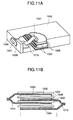
- Fig. 11A is a schematic view of a rectangular cell housed within a cell case
- Fig. 11B is a schematic constitutional view of a conventional rectangular cell.
- 901 is a positive electrode sheet made of positive electrode active material
- 902 is a collector lead
- 903 is a negative electrode sheet made of negative electrode active material.
- 904 is a collector
- 905 is a separator holding an electrolyte
- 906 is a cell case (negative electrode can)
- 907 is a positive electrode cap
- 908 is an insulating gasket
- 909 is an insulating plate
- 910 is an insulator or separator.
- This spirally wound cylindrical cell is constituted by packing the positive electrode sheet 901, the separator 905 and the negative electrode sheet 903, in a sandwiched and wound structure, within the cell case 906, connecting thereto a lead extended from the collector, adding an electrolyte thereto, and putting the positive electrode cap 907 thereon.
- 1001 is a positive plate made of positive electrode active material
- 1002 is a collector
- 1003 is a negative plate made of negative electrode active material
- 1004 is a collector
- 1005 is a separator holding an electrolyte
- 1006 is a cell case (negative electrode can)
- 1007 is a positive electrode terminal
- 1008 is an insulating gasket
- 1009 is a cap
- 1010 is a collector lead.
- the positive plate 1001 and the negative plate 1003 are laminated with the separator 1005 therebetween, as shown in Fig. 11B.
- the rectangular cell will occupy only a smaller dead space when accommodated within the device than the spirally wound cylindrical cell.
- the spirally wound cylindrical cell can have a larger plate area, and a greater bulk density per volume of cell main body than the rectangular cell. Therefore, the conventional rectangular cell can have only a smaller plate area than the spirally wound cylindrical cell, and thus is difficult to pass as high a current flow as the spirally wound cylindrical cell, resulting in a substantial low energy density.
- the rectangular cell has a problem that it is involved in more manufacturing processes, and more complicated than the spirally wound cylindrical cell, because the rectangular cell involves the lamination of a plurality of positive and negative plates and the connection of a plurality of collector leads while the spirally wound cylindrical cell is made by the continuous lamination of positive electrode and negative electrode.
- GB-A-1,078,135 discloses a battery cell in which positive and negative regions of electro-active material are alternatively deposited along the length of two carrier strips. The two strips are juxtaposed in a staggered configuration so as to produce a series of unit cells.
- the present invention has been achieved to solve the above-mentioned conventional problem, and its objective is to provide a rectangular cell or sheet-like cell, which is able to supply a large current flow, has a great energy density per volume, and is simple to manufacture.
- a battery comprising: positive electrode active material; negative electrode active material; an insulating sheet member arranged between said negative electrode active material and said positive electrode active material; and an electrolyte, the battery being characterised in that said insulating sheet member includes a plurality of positive pole regions carrying said positive electrode active material and a plurality of negative pole regions carrying said negative electrode active material, with respective pairs of said negative pole regions and said positive pole regions being disposed on said insulating sheet member to form unit cells, the respective pairs of negative and positive pole regions facing away from each other with the plurality of unit cells formed on said insulating sheet member being separated from each other by blank sections of said insulating sheet member where said positive pole regions and said negative pole regions are not provided, adjacent unit cells being electrically connected.
- a method for producing a battery comprising the steps of: forming, on a sheet-like insulating member, positive pole regions having positive electrode active material and negative pole regions having negative electrode active material separately from each other; the method being characterised by the further steps of: folding the sheet-like insulating member such that respective pairs of positive pole regions and negative pole regions are in opposition to each other; and fusing the sheet-like insulating member at blank sections where the positive pole regions and the negative pole regions are not provided to form unit cells.
- the present invention is a cell characterized in that a bendable (foldable) flexible material is used for the insulating substrate to fold regions having no active material and accommodate the cell within the cell case.
- the present invention is particularly effective for secondary cells which can be charged in short time, because of the possibility of employing a thin plate, providing a larger plate area and supplying a larger current flow. Further, the present invention allows for easy serialization of unit cells, and easy fabrication of high voltage type cells.
- Figs. 1A to 4 are views for explaining the present invention.
- Figs. 1A and 1B show positive electrodes and negative electrodes in a plurality of regions formed on a sheet-like insulating substrate before folding.
- Fig. 1A is a parallel connection type in which pairs of positive electrode and negative electrode are connected in parallel via collectors.
- Fig. 1B is a serial connection type of unit cells in which pairs of positive electrode and negative electrode are connected serially via collectors to enhance the cell voltage.
- 100 is a sheet-like insulating member
- 101 is a positive electrode
- 102 and 104 are collectors
- 103 is a negative electrode
- 106 is a protective sheet.
- the insulating member 100 may be also used as the separator.
- a material of the separator may be used.
- electrodes to be paired are provided on respective insulating members, but may be provided on the same insulating member. In such a case, it is necessary that the material of insulating member has fine pores, which allow the insulating material to fulfill a function of the separator.
- the collectors 102 and 104 each may be provided between the insulating member and the positive or negative electrode, or on or in the positive or negative electrode.
- a sheet-type cell of the high voltage type can be readily fabricated. Thereby, the fabrication of a thin sheet cell of the high voltage type is allowed.
- a rectangular cell is fabricated in such a way as to fold a sheet having a plurality of unit cells laminated as shown in Figs. 1A and 1B along the regions having no active material for the accommodation within a cell case as shown in Fig. 11A, connect the leads of positive and negative electrodes thereto, pour an electrolyte, and then put a cap thereon.
- the above procedure makes it possible to employ a larger electrode area and a thinner plate, and thus allows for the manufacturing of cells of the high capacity type capable of passing a large current flow. Also, the serialization can be easily made within one cell, resulting in a higher utilization ratio of the cell storage space.
- FIG. 2 Examples of folding the sheet having a plurality of unit cells of Figs. 1A and 1B laminated are shown in Figs. 2, 3 and 4.
- Fig. 2 is a typical view showing how to fold a serial connection type of unit cells as shown in Fig. 1B in a screen-like form.
- 200 is an insulating substrate which also serves as the separator
- 201 is a positive electrode made of positive electrode active material
- 203 is a negative electrode made of negative electrode active material
- 202 and 204 are collectors (no protective sheet is shown in Fig. 2).
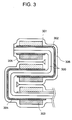
- Fig. 3 is a schematic cross-sectional view in which a pair of sheet-like insulating substrates having positive electrodes and negative electrodes formed in a plurality of regions separated from each other as shown in Fig. 1B are put together so that the positive electrode and the negative electrode as a pair may be opposed to each other, covered with a protective sheet, and folded like a screen.
- a protective sheet In practical fabrication of cells, by incorporating this folded screen into a rectangular cell case, cells having a high cell voltage and a large capacity can be made.
- 300 is an insulating substrate which also serves as the separator, 301 is a positive electrode made of positive electrode active material, 303 is a negative electrode made of negative electrode active material, 302 and 304 are collectors, and 306 is a protective sheet.
- the separator or insulating substrate as indicated at 300 contains an electrolyte therein.
- Fig. 4 is a typical view showing how to fold up inwardly in a different direction from that of Fig. 2.
- 400 is an insulating substrate which also serves as the separator
- 401 is a positive electrode made of positive electrode active material
- 403 is a negative electrode made of negative electrode active material
- 402 and 404 are collectors (no protective sheet is shown in Fig. 4).
- a continuous collector as shown in Fig. 1A is used on the insulating member.
- discontinuous collectors spaced at a constant interval as shown in Fig. 1B are disposed so that opposed collectors with electrodes may overlap each other when the cell is constructed.
- positive electrode and negative electrode are formed in a plurality of regions separated from each other on the collectors, using active materials.
- positive electrodes and negative electrodes are formed in a plurality of regions separated from each other on the collector to be provided on the insulating member. Thereafter, in connecting unit cells in parallel, a continuous collector is provided on the insulating member. In connecting unit cells in serial, discontinuous collectors spaced at a constant interval are disposed so that opposed collectors with electrodes may overlap each other, when the cell is constructed.
- Fig. 5 is an example in which positive electrodes and negative electrodes are formed in a plurality of regions separated from each other on the same plane of the insulating substrate.
- 500 is an insulating substrate
- 501 is a positive electrode
- 503 is a negative electrode
- 502 and 504 are collectors.
- Figs. 7A and 7B By folding up along the line A-B, a plurality of unit cells connected in parallel or serial can be constructed. There are two folding directions, i.e., inward and outward, which are typically shown in Figs. 7A and 7B.
- 700 is an insulating substrate
- 701 is a positive electrode
- 703 is a negative electrode
- 702 and 704 are collectors
- 705 is a separator.
- the insulating substrate as indicated by 700 can be also used as the separator.
- Fig. 6 is a view in which positive electrode and negative electrode are formed in a plurality of regions separated from each other on the same insulating substrate to fabricate a parallel or serial connection type of unit cells (this example is different from that of Fig. 5).
- 600 is an insulating substrate
- 601 is a positive electrode
- 603 is a negative electrode
- 602 and 604 are collectors.
- the materials of insulating member include a glass, ceramics, and organic resins.
- the organic resin may include polyethylene, polypropylene, fluororesin, polyimide, polyamide, vinyl chloride, polyurethane, and polystyrene.
- the insulating member is folded to make the shape of a rectangular cell, and therefore required to have flexibility. When the insulating member is also used as the separator, it is desirable to have a micropore structure and the liquid retainability.
- the cut line should be provided along the folding part in the insulating member to make the folding easier and suppress the stress from occurring after the accommodation within the cell case.
- the cut line provided in the insulating member may take any shape inasmuch as the insulating member can be readily folded.
- the surface of the insulator on which active material or collectors are provided is desirably subjected to corona discharge treatment, plasma treatment, treatment with coupling agent, or etching treatment in order to enhance the contactness.
- the source gases for the plasma for use with the plasma treatment include gases of hydrogen, oxygen, nitrogen, argon, ammonia, and hydrocarbon.
- the coupling agents may include a silane coupling agent, and a titanate coupling agent.
- the insulating substrate may be preformed with patterns of conductive material for the collector electrode.
- Such collector electrode patterns of conductive material can be formed by plating, vapor deposition, or printing with conductive paste.
- the materials of collector include conductive materials such as carbon, stainless steel, titanium, nickel, copper, aluminum, platinum and gold.
- the collector may be provided in a thin film or foil, fibrous, porous or meshy.
- the ways of providing the collector include plating or depositing a conductive material on the insulating substrate or the positive and negative electrodes provided on the insulating substrate, printing a conductive paste, or ultrasonic welding or pressure connecting a fibrous, porous or meshy conductive sheet.
- a mixture of an active material, a conductor powder and a binding agent is prepared to a paste having an adequate viscosity by adding a solvent as necessary, applied over a plurality of regions on the insulating substrate, dried and cured.
- the application methods may include screen printing and coating by coater, spray, and electrodeposition.
- the negative electrode active material is as soft as metal lithium and itself has a conductivity
- the method is not limitative to those above cited, and the negative electrodes can be formed on the insulating substrate by pressure connection without the use of any conductor powder and binding agent.
- the role of conductor powder is to help the electronic conduction and facilitate the current collection when the active material involves poor conductivity.
- Examples of the conductor powder may include various carbon materials such as acetylene black, ketene black, and graphite powder, and metallic materials such as nickel, titanium, copper, stainless steel, and aluminum.
- the mixture weight ratio of conductor powder to active material is preferably 1 or less.
- Binding agent has a role of connecting active material powders together to prevent them from falling off the collector due to crack occurring in charging and discharging cycles, when the moldability of active material is poor.
- the materials of binding agent may include fluororesin, polyethylene, polypropylene, and silicone resin, which are stable in solvent when electrolyte is non-water.
- the resin should be in liquid or solution, or have a lower melting point, because the content ratio of binding agent in the electrode can be lowered, and thus the cell capacity can be increased.
- Specific examples of the resin liquid or solvable in the solvent may include, in addition to polyethylene and polypropylene, fluororesin and silicone resin having ether linkage. In particular, when fluororesin having ether linkage is used, fluororesin can be dissolved in the solvent to be used at lower concentration, resulting in decreased content ratio of binding agent in the positive electrode to the minimum and raised void ratio.
- an aqueous electrolyte should be subjected to hydrophilic treatment in use.
- the electrolyte is an aqueous solution
- other binding agents including cellulose, polyvinyl acetate, polyethylene glycol, and polyethylene oxide may be also used.
- the negative electrode active materials may include lithium or lithium alloy, and sodium.
- Examples of lithium alloy include alloys of lithium with magnesium, aluminum, potassium, sodium, calcium, zinc, and lead.
- the positive electrode active materials typically may include transition metallic oxides, transition metallic sulfides, chlorine, graphite fluoride, thionyl chloride, sulfur dioxide, and sulfur.
- the transition metal elements for transition metallic oxides or transition metallic sulfides may be elements partially having d shell or f shell, such as Sc, Y, lanthanoid, actionoid, Ti, Zr, Hf, V, Nb, Ta, Cr, Mo, W, Mn, Tc, Re, Fe, Ru, Os, Co, Rh, Ir, Ni, Pd, Pt, Cu, Ag, and Au.
- the first transition series metals including Ti, V, Cr, Mn, Fe, Co, Ni, and Cu are used.
- the negative electrode active materials may include lead, cadmium, hydrogen storage material, zinc, iron, and magnesium.
- the positive electrode active materials may include lead oxide, nickel hydroxide oxide, silver oxide, manganese dioxide, oxygen, bromine, chlorine, silver chloride, lead chloride, and copper chloride.
- Separator has a role of preventing short-circuit between negative electrode and positive electrode. Also, it has a further role of holding electrolyte. Separator has fine pores through which ions involving cell reaction can move, and is required to be insolvable and stable in the electrolyte, and may be a non-woven fabric made of glass, polypropylene, polyethylene, fluororesin, polyamide, or materails of micro-pore structure.
- Electrolyte may be used in a chemical state, or in a solution of electrolyte dissolved in the solvent, or by solidifying with a gelatinizer such as a polymer added to the solution.
- a gelatinizer such as a polymer added to the solution.
- an electrolytic solution having electrolyte dissolved in the solvent is used held on a porous separator.
- electrolyte or electrolytic solution electrolysis solution
- the conductivity at 25°C being desirably at least 1 x 10 -3 S/cm or more, and more preferably 5 x 10 -3 S/cm or more.
- electrolyte may include acids such as H 2 SO 4 , HCl, and HNO 3 , salts composed of lithium ion (Li + ) and Lewis acid ions (BF 4 - , PF 6 - , AsF 6 - , ClO 4 - ), and blended salts thereof.
- acids such as H 2 SO 4 , HCl, and HNO 3
- salts composed of lithium ion (Li + ) and Lewis acid ions BF 4 - , PF 6 - , AsF 6 - , ClO 4 -
- salts of Lewis acid ion with cations such as sodium ion, potassium ion, and tetraalkylammonium ion may be used.
- the above-cited salts are desirably subjected to sufficient dehydration and deoxidation by heating under low pressure.
- Examples of the solvent for electrolyte may include acetonitrile, benzonitrile, propylene carbonate, ethylene carbonate, dimethylformamide, tetrahydrofuran, nitrobenzene, dichloroethane, diethoxyethane, chlorobenzene, ⁇ -butyrolactone, dioxolane, sulfolane, nitromethane, dimethylsulfide, dimethylsulfoxide, dimethoxyethane, methylformate, 3-methyl-2-oxazolidinone, 2-methyltetrahydrofuran, sulfur dioxide, phosphoryl chloride, thionyl chloride, sulfuryl chloride, and mixture liquids thereof.
- the above-cited solvents may be dehydrated by activated alumina, molecular sieve, phosphorus pentoxide, or calcium chloride, or distilled with alkaline metal in inert gas to remove impurities and effect dehydration, depending on the solvent.
- Gelatinizer may be desirably a polymer which absorbs the solvent of electrolysis solution and swells, examples of which include polymers such as polyethylene oxide, polyvinyl alcohol, and polyacrylamide.
- Electrolyte may be sulfuric acid in the case of lead cell, or potassium hydroxide, sodium hydroxide, lithium hydroxide, ammonium hydroxide, or a salt of alkali and zinc bromide in the case of alkaline cell.
- Gelatinizer may be desirably a polymer which absorbs the solvent of electrolysis solution and swells, examples of which include polymers such as polyethylene oxide, polyvinyl alcohol, and polyacrylamide, and starch.
- the surface of negative electrode or positive electrode, or both surfaces should be covered with a film through which ions involving the cell reaction can penetrate so as to elongate the cycle life of the cell.
- the covering material may include large ring compound derivative polymer, aromatic hydrocarbon derivative polymer, fluororesin, silicone resin, titanium resin, polyolefine, or inorganic oxide, nitride, carbide, and halide.
- the covering of positive electrode with large ring compound derivative polymer, aromatic hydrocarbon derivative polymer, or fluororesin is especially effective for lithium secondary cells.
- Cell case may be an outer packaging can made of a metallic material which is also used as the output terminal, or a resin material case made of plastic.
- the materials for the outer packaging can or cap include stainless steel, especially, titanium clad stainless and copper clad stainless, zinc, and nickel plated steel sheet.
- the materials for the plastic case may include plastics such as polypropylene and polyethylene, and composites of plastics with metal or glass fiber.
- the materials for the insulating packing may include fluororesin, polyamide resin, polysulfone resin, and various rubbers.
- the way of sealing the opening may include, in addition to caulking using a gasket such as an insulating packing, the use of adhesives, welding and soldering.
- a gasket such as an insulating packing
- the materials of the insulating plate for the insulation and isolation within the cell may include various organic resin materials, and ceramics.
- the safety measure against the elevated internal pressure within the cell involves the use of a safety valve comprised of a rubber, a spring, or a metallic ball.
- Cell is fabricated in such a way that active materials and an electrolyte are selected in accordance with a cell to be fabricated, such as lithium cell, nickel cadmium cell, nickel hydrogen storage material cell, nickel zinc cell, lead cell, and air cell; a sheet of the parallel type or serial type consisting of a plurality of unit cells is made by the previously-described method, with a separator and a protective sheet interposed, folded up as appropriate in conformity with the cell case, and housed within the cell case; the positive electrode and the negative electrode are connected to the cell terminal; the electrolyte is poured therein; and the sealing is made.
- active materials and an electrolyte are selected in accordance with a cell to be fabricated, such as lithium cell, nickel cadmium cell, nickel hydrogen storage material cell, nickel zinc cell, lead cell, and air cell; a sheet of the parallel type or serial type consisting of a plurality of unit cells is made by the previously-described method, with a separator and a protective sheet interposed, folded up as
- a rectangular lithium cell having a plurality of unit cells connected in parallel within a cell was fabricated in an argon gas in accordance with the following procedure.
- a positive electrode active material was prepared by mixing acetylene black, nickel super fine powder, Lumifron (fluororesin, manufactured by Asahi Glass) into manganese dioxide, adding xylene, and adjusting the viscosity.
- a positive electrode active material paste prepared was printed in a plurality of regions for the formation of positive electrodes on the polypropylene non-woven fabric subjected to the surface treatment by a screen printing apparatus, on which a nickel meshed collector sheet with the lead was disposed, and dried. Then, a plurality of lithium foils cut into a size of unit negative electrode was pressure connected with the nickel meshed collector sheet with the lead, covered with a Lumifron thin film manufactured by Asahi Glass, and disposed on negative electrode forming regions on the polypropylene non-woven fabric printed with the positive electrodes.
- a protective sheet made of polypropylene film was superposed on the polypropylene non-woven fabric provided with the positive and negative electrodes and the collectors, the entirety of which were pressure connected by a roll press machine with the film thickness adjusted, whereby a sheet with patterns having a plurality of positive electrodes and negative electrodes arranged as shown in Fig. 6 was made after the heat treatment at 100°C.
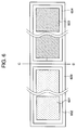
- This sheet was cut into unit sheets as shown in Fig. 6.
- 600 is a polypropylene non-woven fabric
- 601 is a positive electrode composed of positive electrode active material
- 603 is a lithium negative electrode
- 602 and 604 are nickel collectors.
- the sheet was folded along the C-D line between patterns of positive electrode and negative electrode in a unit sheet of Fig. 6 obtained, as shown in Fig. 7B, into which a polypropylene film of micropore structure was interposed, and further folded up like a screen, as shown in Fig. 2, whereby a parallel connection type of unit cells was fabricated as shown in Fig. 3. Then, this rectangular cell was housed in a cell case made of titanium clad stainless, as shown in Fig.
- the rectangular cell fabricated was discharged for ten hours to calculate the capacity, resulting in an increased capacity of 40% as compared with the cylindrical cell of U-3 (AA) size. Also, since the thickness of positive electrode and negative electrode could be made thinner, and the area could be increased, the flow of a large current could be easily passed, like is spirally wound cylindrical cell. Also, the manufacturing process could be facilitated as compared with that of the conventional rectangular cell.
- An integrated sheet-type lithium cell having two pairs of unit cells connected in serial within a cell was fabricated in an argon gas atmosphere in accordance with the following procedure.
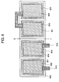
- a manganese dioxide paste prepared in the same way as in the embodiment 1 was printed by screen printing on positive electrode forming regions 801 on a polypropylene film 800 having a micropore structure subjected to corona discharge treatment. Then, nickel mesh collectors 802 with nickel foil leads were laid thereon, and lithium foils having nickel mesh collectors 804 pressure connected were laid on negative electrode forming regions 803 on the propylene film and dried. Then, it was sandwiched between an aluminum laminate film having an aluminum foil laminated with a resin film, and a separator of polypropylene non-woven fabric, and then passed through a heating roll for the pressure connection.
- Fig. 9A is a cross-sectional view of a cell obtained by lamination.
- 800 is a polypropylene film
- 801 is a positive electrode
- 803 is a negative electrode
- 802 and 804 are collectors
- 805 is a separator
- 806 is an aluminum laminate film
- 807 is a fusing part.
- the above-mentioned fusing process is to separate adjacent unit cells at the fusing part 807. Without this separation, an electromotive force may occur between adjacent positive and negative electrodes, despite the serialization within the cell, so that twice voltage of unit cell can not be attained.
- Fig. 9B is a schematic constitutional view of a cell constituted from the laminate cell.
- 806 is an aluminum laminate film
- 808 is a positive electrode terminal
- 809 is a negative electrode terminal
- 810 is a lead
- 811 is a cell case
- 812 is a safety valve
- 813 is a pin for exhausting the laminate cell to lower pressure by opening a hole when the internal pressure of the laminate cell is raised.
- the cell voltage of the sheet-type lithium cell obtained reached an output of 6 volts with the single cell.
- a negative electrode active material paste was prepared by mixing foliate graphite, nickel super fine powder, polyethylene powder, and polyvinyl alcohol powder into Mm (misch metal)-Ni-Ti-Zr-Mn-V-Co alloy powder, and adding tetrahydrofuran thereto, with the viscosity adjusted.
- a positive electrode active material paste was prepared by mixing nickel powder, cobalt monoxide, foliate graphite, polyethylene powder, and polyvinyl alcohol powder, in various shapes such as flake, spheroidal, and spicular shapes, into nickel hydroxide, and adding tetrahydrofuran thereto, with the viscosity adjusted.
- Positive electrode active material paste and negative electrode active material paste as above prepared were printed on a plurality of positive and negative electrode forming regions on the polyamide non-woven fabric subjected to the surface treatment by a screen printing apparatus, on which nickel meshed collector sheets with the leads were disposed, and dried. Then, a protective sheet made of polyester film was superposed on the polyamide non-woven fabric provided with the positive and negative electrodes and the collectors, and pressure connected by a roll press machine, with the film thickness adjusted, whereby a sheet with a plurality of patterns arranged as shown in Fig. 6 was made through the heat treatment at 100°C. This sheet was cut into unit sheets as shown in Fig. 6.
- the sheet was folded along the C-D line between patterns of positive electrodes and negative electrodes in a unit sheet of Fig. 6 obtained, as shown in Fig. 7B, into which a polypropylene film of micropore structure subjected to hydrophilicity treatment was interposed, and further folded like a screen as shown in Fig. 2, whereby a parallel connection type of unit cells was fabricated as shown in Fig. 3.
- the rectangular cell was housed within a cell case made of titanium clad stainless, with the lead parts of the collector for the positive electrode and negative electrode being connected to the cell terminals, an electrolyte prepared by dissolving 6 M (mol/l) potassium hydroxide solution having lithium hydroxide added was poured thereinto, and an insulating packing and a cap made of titanium clad stainless were put thereon and caulked, whereby the rectangular cell in a size of 14.5 millimeters x 7.5 millimeters x 48.4 millimeters was fabricated.
- the rectangular cell thus fabricated was discharged for ten hours to calculate the capacity, resulting in an increased capacity of 40% as compared with the lamination-type cell as shown in Fig. 11B.
- a nickel cadmium cell was fabricated substantially in accordance with the same procedure as the example 3.
- a rectangular nickel cadmium cell having a size of 23 millimeters x 14.7 millimeters x 67 millimeters was fabricated in the same way as in the example 3, except that a negative electrode active material paste was prepared using cadmium oxide powder, instead of hydrogen storage material powder as the negative electrode active material in the example 3.
- the rectangular cell thus fabricated was discharged for ten hours to calculate the capacity, resulting in an increased capacity of 15% as compared with the lamination-type cell as shown in Fig. 11B.
- the cell having a higher capacity can be fabricated than the cylindrical cell and the rectangular cell of lamination structure. Further, from the example 2, it has been also found that by integrating unit cells within the cell, the cell having a still higher cell voltage can be easily fabricated.
- the present invention in the rectangular or sheet-type cell, it is possible to attain an energy density equivalent to that of the cylindrical cell of spiral structure, and pass the flow of a large current, with the dead space of the cell storage space reduced to the utmost. Further, since the integration can be effected even with a single cell, it is possible to attain a higher cell voltage. Also, the manufacturing process of the rectangular cell can be simplified.
Landscapes
- Engineering & Computer Science (AREA)
- Manufacturing & Machinery (AREA)
- Chemical & Material Sciences (AREA)
- Chemical Kinetics & Catalysis (AREA)
- Electrochemistry (AREA)
- General Chemical & Material Sciences (AREA)
- Secondary Cells (AREA)
- Primary Cells (AREA)
- Battery Electrode And Active Subsutance (AREA)
Claims (29)
- Batterie miteinem aktiven Positivelektrodenmaterial (101; 201; 301; 401; 501; 601; 701; 801),einem aktiven Negativelektrodenmaterial (103; 203; 303; 403; 503; 603; 703; 803),einem Isolationslagenelement (100; 200; 300; 400; 700; 800), das zwischen dem aktiven Negativelektrodenmaterial (103; 203; 303; 403; 703; 803) und dem aktiven Positivelektrodenmaterial (101; 201; 301; 401; 701; 801) angeordnet ist, undeinem Elektrolyt,
dadurch gekennzeichnet, daßdas Isolationslagenelement (100; 200; 300; 400; 500; 600; 700; 800) eine Vielzahl von Positivpolbereichen, die das aktive Positivelektrodenmaterial (101; 201; 301; 401; 701; 801) tragen, und eine Vielzahl von Negativpolbereichen, die das aktive Negativelektrodenmaterial (103; 203; 303; 403; 703; 803) tragen, umfaßt, wobei entsprechende Paare der Negativpolbereiche und der Positivpolbereiche so auf dem Isolationslagenelement (100; 200; 300; 400; 500; 600; 700; 800) angeordnet sind, daß sie Zelleneinheiten bilden und voneinander wegweisen, und wobei die Vielzahl der auf dem Isolationslagenelement (100; 200; 300; 400; 800) ausgebildeten Zelleneinheiten durch Leerabschnitte des Isolationslagenelementes (100; 200; 300; 400; 800), an denen die Positivpolbereiche und Negativpolbereiche nicht vorgesehen sind, voneinander getrennt ist, wobei benachbarte Zelleneinheiten elektrisch angeschlossen sind. - Batterie nach Anspruch 1, bei der das Isolationslagenelement (200; 300; 400; 500; 600; 700; 800) einen gefalteten Abschnitt mit einer Faltlinie in einem Bereich (A-B; C-D; E-F), der kein aktives Material trägt, umfaßt, wobei die entsprechenden Paare der Negativ- und Positivpolbereiche auf den auswärts gerichteten Flächen des gefalteten Abschnittes vorgesehen sind.
- Batterie nach Anspruch 2, bei der das Isolationslagenelement (200; 300; 400; 500; 600; 700; 800) wie ein Sieb ausgebildet ist.
- Batterie nach Anspruch 1, bei der die Positivelektrodenbereiche (101; 201; 301; 401; 501; 601; 701; 801) und die Negativelektrodenbereiche (103; 203; 303; 403; 503, 603; 703; 803) auf der gleichen Ebene des Isolationslagenelementes (100; 200; 300; 400; 500; 600; 700; 800) vorgesehen sind.
- Batterie nach Anspruch 4, bei der die Positivelektrodenbereiche (101; 201; 301; 401; 801) und die Negativelektrodenbereiche (103, 203; 303; 403; 803) abwechselnd auf der gleichen Ebene des Isolationslagenelementes (100; 200; 300; 400; 800) vorgesehen sind.
- Batterie nach Anspruch 1, bei der entweder Positivelektrodenbereiche (101; 801) oder Negativelektrodenbereiche (103; 803) auf der gleichen Ebene des Isolationslagenelementes (100; 800) vorgesehen sind.
- Batterie nach Anspruch l mit einem Kollektor (802, 804), der in bezug auf jeden Positivpolbereich und jeden Negativpolbereich vorgesehen ist, wobei jeder Kollektor (802, 804) in einem kleineren Bereich vorgesehen ist als der entsprechende Positiv- oder Negativpolbereich.
- Batterie nach Anspruch 1 mit einem Kollektor (102; 104; 202; 204; 302; 304; 402; 404; 802, 804) in bezug auf jeden Positv- oder Negativpolbereich, wobei jeder Kollektor (102, 104; 202, 204; 302, 304; 402, 404; 802, 804) diskontinuierlich und regelmäßig in einer Vielzahl von Bereichen vorgesehen ist, die mindestens auf einer Seite des Isolationslagenelementes ((100; 200; 300; 400; 800) voneinander getrennt sind, um eine serielle Anordnung der Zelleneinheiten zu bewirken.
- Batterie nach Anspruch 8 mit zwei gegenüberliegenden Kollektoren (202, 204; 302, 304; 402, 404; 802, 804), wobei das Isolationslagenelement (200; 300; 400; 800) hierzwischen angeordnet ist.
- Batterie nach Anspruch 8, bei der die Kollektoren (102; 104; 202, 204; 302, 304; 402, 404) zwischen dem Isolationslagenelement (100; 200; 300; 400) und dem aktiven Material (101; 103; 201, 203; 301, 303; 401, 403) vorgesehen sind.
- Batterie nach Anspruch 8 oder 9, bei der die Kollektoren (802, 804) in oder auf dem aktiven Material vorgesehen sind, das auf dem Isolationslagenelement (800) vorgesehen ist.
- Batterie nach Anspruch 1, bei der das Isolationslagenelement (100; 200; 300; 400; 800) feine Poren aufweist, die eine Trennrolle übernehmen.
- Batterie nach Anspruch 1, bei der das Isolationslagenelement (100; 300; 800) von zwei oder mehr Lagen gebildet ist.
- Batterie nach Anspruch 1, bei der die Positivelektrodenbereiche (801) oder Negativelektrodenbereiche (803) geformt sind, indem eine hauptsächlich aus einem aktiven Material bestehende Substanz auf das Isolationselement (800) aufgebracht ist.
- Batterie nach Anspruch 2, bei der mindestens ein Teil des gefalteten Abschnittes dünner ist als andere Abschnitte des Isolationselementes (200; 300; 400; 500; 600; 700; 800).
- Batterie nach Anspruch 2, bei der mindestens ein Teil des gefalteten Abschnittes eine Schnittlinie aufweist.
- Batterie nach Anspruch 1, bei der die Zelleneinheiten mindestens über verschmolzene Bereiche (807) des Isolationslagenelementes (800) voneinander getrennt sind.
- Batterie nach Anspruch 13, bei der mindestens eine der Isolationslagen ein Separator (809) ist.
- Batterie nach Anspruch 1, bei der das Isolationslagenelement (800) eine Vielzahl von Lagen umfaßt, wobei mindestens eine der Lagen ein Separator (805) ist, und die Zelleneinheiten durch Verschmelzen der Lagen getrennt sind.
- Batterie nach einem der vorangehenden Ansprüche, bei der das Isolationslagenelement (100; 200; 300; 400; 500; 600; 700; 800) aus einem organischen Polymer hergestellt ist.
- Verfahren zur Herstellung einer Batterie, bei demauf einem Isolationslagenelement (800) Positivpolbereiche (801) mit einem aktiven Positivelektrodenmaterial und Negativpolbereiche (803) mit einem aktiven Negativelektrodenmaterial getrennt voneinander ausgebildet werden,
gekennzeichnet durch die folgenden weiteren Schritte:Falten des Isolationslagenelementes (800) derart, daß sich entsprechende Paare von Positivpolbereichen (801) und Negativpolbereichen (803) gegenüberliegen, undVerschmelzen des Isolationslagenelementes (800) an Leerabschnitten (807), an denen die Positivpolbereiche und die Negativpolbereiche nicht vorgesehen sind, um Zelleneinheiten zu bilden. - Verfahren nach Anspruch 21, bei dem das Isolationselement an mindestens einem der Leerabschnitte (807) gefaltet wird (800).
- Verfahren nach Anspruch 21, das des weiteren den Schritt der Anordnung einer Vielzahl von Isolationslagenelementen (800) und eines Separators (805) umfaßt, wobei ein Isolationselement (800) auf gegenüberliegenden Seiten des Separators (805) angeordnet und das Verschmelzen auch am Separator (805) durchgeführt wird.
- Verfahren nach Anspruch 21, das die Schritte der Anordnung der Positivpolbereiche (801) und der Negativpolbereiche (803) einander gegenüber, der Anordnung des Isolationslagenelementes (800) und eines anderen Separators (805) dazwischen unddas Verschmelzen des Isolationslagenelementes (800) am Leerabschnitt (807) zusammen mit dem anderen Separator (805) umfaßt.
- Verfahren nach Anspruch 21, bei dem die Positivpolbereiche (801) und die Negativpolbereiche (803) auf einer Seite des Isolationslagenelementes (800) ausgebildet werden unddas den Schritt des Faltens des lagenförmigen Elementes entlang mindestens einer Linie (E-F) des Leerabschnittes des Lagenelementes (800) umfaßt, derart, daß die positiven Pole (801) und die negativen Pole (803) einander gegenüberliegend angeordnet sind und das Lagenelement (800) zwischen sich aufnehmen.
- Verfahren nach Anspruch 21, bei dem die Positvpolbereiche (801) und die Negativpolbereiche (803) auf einer Seite des Isolationslagenelementes (800) ausgebildet werden,ein Separator (805) in mindestens einem vorgegebenen Bereich auf der anderen Seite des Isolationslagenelementes (800) vorgesehen wird,mit dem Schritt des Faltens des Lagenelementes (800) entlang mindestens einer Linie (E-F) der Leerabschnitte des Lagenelementes (800) undwobei die Positivpolbereiche (801) und die Negativpolbereiche (803) einander gegenüberliegend angeordnet werden und zwischen sich das Isolationslagenelement (800) und den Separator (805) aufnehmen.
- Verfahren nach Anspruch 21, bei dem die Positivpolbereiche (801) und die Negativpolbereiche (803) auf einer Seite des Isolationslagenelementes (800) ausgebildet werden, wobei das Verfahren die folgenden weiteren Schritte umfaßt:Pressen eines Laminatfilmes (806) in Kontakt mit den Positivpolbereichen (801) und Negativpolbereichen (803) auf der einen Seite undPressen eines Separators (805) in Kontakt mit mindestens einem vorgegebenen Bereich auf der anderen Seite des Isolationslagenelementes (800),Falten des Isolationslagenelementes (800) entlang mindestens einer Linie (E-F) der Leerabschnitte des Lagenelementes (800),Anordnen der Positivpolbereiche (801) und der Negativpolbereiche (803) einander gegenüberliegend, so daß sie das Isolationslagenelement (800) und den Separator (805) zwischen sich aufnehmen, undVerschmelzen des Isolationslagenelementes (800) am Leerabschnitt (807) zusammen mit dem Separator (805) und dem Laminatfilm (806).
- Verfahren nach einem der Ansprüche 21 bis 27, bei dem das Isolationslagenelement (800) aus einem organischen Polymer hergestellt wird.
- Verfahren nach einem der Ansprüche 21 bis 28, das den weiteren Schritt der Anordnung der Zelleneinheiten in einem Gehäuse (811) umfaßt.
Applications Claiming Priority (3)
| Application Number | Priority Date | Filing Date | Title |
|---|---|---|---|
| JP33880692 | 1992-12-18 | ||
| JP338806/92 | 1992-12-18 | ||
| JP33880692A JP3397351B2 (ja) | 1992-12-18 | 1992-12-18 | 角型あるいはシート型電池及びその製造方法 |
Publications (2)
| Publication Number | Publication Date |
|---|---|
| EP0602976A1 EP0602976A1 (de) | 1994-06-22 |
| EP0602976B1 true EP0602976B1 (de) | 2000-04-19 |
Family
ID=18321646
Family Applications (1)
| Application Number | Title | Priority Date | Filing Date |
|---|---|---|---|
| EP93310172A Expired - Lifetime EP0602976B1 (de) | 1992-12-18 | 1993-12-16 | Rechteckige Zelle und Verfahren zur Herstellung |
Country Status (5)
| Country | Link |
|---|---|
| US (2) | US5582931A (de) |
| EP (1) | EP0602976B1 (de) |
| JP (1) | JP3397351B2 (de) |
| AU (1) | AU675983B2 (de) |
| DE (1) | DE69328411T2 (de) |
Families Citing this family (137)
| Publication number | Priority date | Publication date | Assignee | Title |
|---|---|---|---|---|
| EP0693227B1 (de) * | 1993-04-07 | 1997-07-16 | William Brown Miller | Verbesserungen bezueglich elektrochemischer zellen |
| GB2298309B (en) * | 1994-11-02 | 1997-10-15 | Sankar Dasgupta | Rechargeable non-aqueous lithium battery having stacked electrochemical cells |
| EP0876683B1 (de) | 1996-01-25 | 2002-09-25 | Danionics A/S | Elektrode/stromkollektor, laminate für eine elektrochemische vorrichtung |
| WO1997036337A1 (fr) * | 1996-03-22 | 1997-10-02 | Hitachi, Ltd. | Pile secondaire au lithium, chargeur et dispositif pour terminal informatique |
| KR19980016522A (ko) * | 1996-08-28 | 1998-06-05 | 김광호 | 리튬이온 2차전지의 제조방법 및 그 방법에 따라 제조된 리튬이온 2차전지 |
| US5972531A (en) * | 1996-12-24 | 1999-10-26 | Canon Kabushiki Kaisha | Process and apparatus for recovering constituent components of battery |
| EP0851517B1 (de) * | 1996-12-26 | 2001-03-21 | Mitsubishi Denki Kabushiki Kaisha | Elektrode mit positiver Temperaturabhängigkeit der elektrischen Leitfähigkeit (PTC) und Batterie |
| US5776628A (en) * | 1997-06-30 | 1998-07-07 | Wilson Greatbatch Ltd. | Flat-folded, multi-plate electrode assembly |
| US5911947A (en) * | 1997-06-30 | 1999-06-15 | Compaq Computer Corporation | Fan-folded polymer-electrolyte cell |
| US6100702A (en) | 1997-07-25 | 2000-08-08 | 3M Innovative Properties Company | In-situ fault detection apparatus and method for an encased energy storing device |
| US6117584A (en) | 1997-07-25 | 2000-09-12 | 3M Innovative Properties Company | Thermal conductor for high-energy electrochemical cells |
| US5952815A (en) | 1997-07-25 | 1999-09-14 | Minnesota Mining & Manufacturing Co. | Equalizer system and method for series connected energy storing devices |
| US6087036A (en) | 1997-07-25 | 2000-07-11 | 3M Innovative Properties Company | Thermal management system and method for a solid-state energy storing device |
| US6120930A (en) | 1997-07-25 | 2000-09-19 | 3M Innovative Properties Corporation | Rechargeable thin-film electrochemical generator |
| US6104967A (en) | 1997-07-25 | 2000-08-15 | 3M Innovative Properties Company | Fault-tolerant battery system employing intra-battery network architecture |
| US6046514A (en) * | 1997-07-25 | 2000-04-04 | 3M Innovative Properties Company | Bypass apparatus and method for series connected energy storage devices |
| US6146778A (en) | 1997-07-25 | 2000-11-14 | 3M Innovative Properties Company | Solid-state energy storage module employing integrated interconnect board |
| US6099986A (en) | 1997-07-25 | 2000-08-08 | 3M Innovative Properties Company | In-situ short circuit protection system and method for high-energy electrochemical cells |
| US6239508B1 (en) | 1997-10-06 | 2001-05-29 | Reveo, Inc. | Electrical power generation system having means for managing the discharging and recharging of metal fuel contained within a network of metal-air fuel cell battery subsystems |
| US6348277B1 (en) | 1997-10-06 | 2002-02-19 | Reveo, Inc. | Method of and system for producing and supplying electrical power to an electrical power consuming device using a metal-air fuel cell battery (FCB) module and a supply of metal-fuel cards |
| US6306534B1 (en) | 1997-10-06 | 2001-10-23 | Reveo, Inc. | Metal-air fuel cell battery systems employing means for discharging and recharging metal-fuel cards |
| US6299997B1 (en) | 1997-10-06 | 2001-10-09 | Reveo, Inc. | Ionically-conductive belt structure for use in a metal-air fuel cell battery system and method of fabricating the same |
| US6287715B1 (en) | 1997-10-06 | 2001-09-11 | Reveo, Inc. | Metal-air fuel cell battery system having means for controlling discharging and recharging parameters for improved operating efficiency |
| US6451463B1 (en) | 1997-10-06 | 2002-09-17 | Reveo, Inc. | Electro-chemical power generation systems employing arrays of electronically-controllable discharging and/or recharging cells within a unity support structure |
| US6558829B1 (en) | 1997-10-06 | 2003-05-06 | Reveo, Inc. | Appliance with refuelable and rechargeable metal-air fuel cell battery power supply unit integrated therein |
| US6641943B1 (en) | 1997-10-06 | 2003-11-04 | Reveo, Inc. | Metal-air fuel cell battery system having means for recording and reading operating parameters during discharging and recharging modes of operation |
| US6472093B2 (en) | 1997-10-06 | 2002-10-29 | Reveo, Inc. | Metal-air fuel cell battery systems having a metal-fuel card storage cartridge, insertable within a fuel cartridge insertion port, containing a supply of substantially planar discrete metal-fuel cards, and fuel card transport mechanisms therein |
| US6569555B1 (en) | 1997-10-06 | 2003-05-27 | Reveo, Inc. | Refuelable and rechargeable metal-air fuel cell battery power supply unit for integration into an appliance |
| US6296960B1 (en) | 1997-10-06 | 2001-10-02 | Reveo, Inc. | System and method for producing electrical power using metal-air fuel cell battery technology |
| US6335111B1 (en) | 1997-10-06 | 2002-01-01 | Reveo, Inc. | Metal-air fuel cell battery system employing a plurality of moving cathode structures for improved volumetric power density |
| US6228519B1 (en) | 1997-10-06 | 2001-05-08 | Reveo, Inc. | Metal-air fuel cell battery systems having mechanism for extending the path length of metal-fuel tape during discharging and recharging modes of operation |
| US6235425B1 (en) | 1997-12-12 | 2001-05-22 | 3M Innovative Properties Company | Apparatus and method for treating a cathode material provided on a thin-film substrate |
| US6265100B1 (en) | 1998-02-23 | 2001-07-24 | Research International, Inc. | Rechargeable battery |
| US20060035698A1 (en) * | 1998-04-14 | 2006-02-16 | Roberts Brian J | Gaming device and method |
| JP4016481B2 (ja) * | 1998-05-14 | 2007-12-05 | ソニー株式会社 | 固体電解質電池 |
| WO1999060651A1 (en) * | 1998-05-15 | 1999-11-25 | Valence Technology, Inc. | Grid placement in lithium ion bi-cell counter electrodes |
| US6063519A (en) * | 1998-05-15 | 2000-05-16 | Valence Technology, Inc. | Grid placement in lithium ion bi-cell counter electrodes |
| US6287719B1 (en) | 1998-06-15 | 2001-09-11 | Eveready Battery Company, Inc. | Battery including a non-aqueous multi-cell spiral-wound electrode assembly |
| DE69927556T2 (de) * | 1998-07-21 | 2006-06-22 | Matsushita Electric Industrial Co., Ltd., Kadoma | Flache Zellen |
| KR100443250B1 (ko) * | 1998-09-24 | 2004-08-04 | 토마스 앤드 베츠 인터내셔널, 인코포레이티드 | 전기화학전지의 개량된 제조방법 |
| GB9900398D0 (en) * | 1999-01-08 | 1999-02-24 | Danionics As | Arrangements of electrochemical cells |
| US6299998B1 (en) | 1999-03-15 | 2001-10-09 | Reveo, Inc. | Movable anode fuel cell battery |
| HUP0001238A3 (en) | 1999-03-25 | 2004-09-28 | Sanyo Electric Co | Rectangular battery |
| US6280873B1 (en) * | 1999-04-08 | 2001-08-28 | Quallion, Llc | Wound battery and method for making it |
| US6379838B1 (en) | 1999-04-14 | 2002-04-30 | Alcatel | Cell package |
| US6444354B1 (en) * | 1999-05-20 | 2002-09-03 | Valence Technology, Inc. | Low impedance folded polymeric laminate rechargeable battery and method of making |
| US6617074B1 (en) * | 1999-06-30 | 2003-09-09 | Mitsubishi Materials Corporation | Lithium ion polymer secondary battery and gelatinous polymer electrolyte for sheet battery |
| KR100537607B1 (ko) * | 1999-08-30 | 2005-12-19 | 삼성에스디아이 주식회사 | 폴딩형 전극군 및 이를 이용한 이차전지 |
| US6528204B1 (en) * | 1999-09-22 | 2003-03-04 | Koninklijke Philips Electronics N.V. | Lithium secondary battery comprising individual cells with one another, as well as watches, computers and communication equipment provided with a battery |
| US6653003B1 (en) | 1999-10-12 | 2003-11-25 | Reveo Inc. | Fuel cell support and electrical interconnector |
| KR100309604B1 (ko) * | 1999-12-20 | 2001-11-03 | 홍지준 | 리튬 2차 전지 |
| DE10015823A1 (de) * | 2000-03-30 | 2001-10-18 | Epcos Ag | Gehäuster Schichtstapel, Verfahren zur Herstellung des gehäusten Schichtstapels und Verwendung des Verfahrens |
| US6558825B1 (en) | 2000-05-12 | 2003-05-06 | Reveo, Inc. | Fuel containment and recycling system |
| KR100336395B1 (ko) | 2000-06-12 | 2002-05-10 | 홍지준 | 리튬 이차 전지의 제조방법 |
| US6482540B1 (en) * | 2000-07-14 | 2002-11-19 | Valence Technology (Nevada), Inc. | Multi-fold rechargeable battery cell structure |
| US6740446B2 (en) * | 2001-02-28 | 2004-05-25 | Ovonic Battery Company, Inc. | Electrochemical cell with zigzag electrodes |
| US6727017B1 (en) * | 2001-04-06 | 2004-04-27 | Changs Ascending Enterprise Co., Ltd. | Methods of fabricating binding layers for a Li-ion polymer battery |
| US6749650B2 (en) * | 2001-05-21 | 2004-06-15 | Delphi Technologies Inc. | System and method for multilayer fabrication of lithium polymer batteries and cells |
| US20020170169A1 (en) * | 2001-05-21 | 2002-11-21 | Gonzalez Jose E. | System and method for multilayer fabrication of lithium polymer batteries and cells using surface treated separators |
| DE10146957A1 (de) * | 2001-09-24 | 2003-04-17 | Nbt Gmbh | Dicht verschlossener Akkumulator |
| DE10150227A1 (de) * | 2001-10-11 | 2003-04-17 | Varta Microbattery Gmbh | Verfahren zur Herstellung eines Elektroden-/Separatorverbundes für galvanische Elemente |
| KR100440929B1 (ko) * | 2001-10-16 | 2004-07-21 | 삼성에스디아이 주식회사 | 각형 2차 전지용 전극 구조 |
| US6830846B2 (en) * | 2001-11-29 | 2004-12-14 | 3M Innovative Properties Company | Discontinuous cathode sheet halfcell web |
| WO2003100901A1 (en) * | 2002-05-23 | 2003-12-04 | Whanjin Roh | Lithium secondary battery and its fabrication |
| KR100958647B1 (ko) * | 2002-12-18 | 2010-05-20 | 삼성에스디아이 주식회사 | 파우치형 이차전지 유니트 |
| JP4594590B2 (ja) * | 2002-12-27 | 2010-12-08 | パナソニック株式会社 | 電気化学素子 |
| US20040142203A1 (en) * | 2003-01-07 | 2004-07-22 | Woolley Christopher P. | Hydrogen storage medium |
| KR100560158B1 (ko) * | 2003-09-29 | 2006-03-16 | 주식회사 코캄 | 고 안전성 리튬 이차 전지 및 그 제조방법 |
| US20060105233A1 (en) * | 2004-11-18 | 2006-05-18 | Hiroyuki Morita | Battery |
| JP4967265B2 (ja) * | 2005-07-13 | 2012-07-04 | 大日本印刷株式会社 | 非水電解液蓄電素子用電極構造体、該電極構造体の製造方法、および非水電解液蓄電素子 |
| KR100840380B1 (ko) | 2006-02-13 | 2008-06-20 | 주식회사 엘지화학 | 코어 팩의 제조를 위한 용접용 지그 |
| US20070212604A1 (en) * | 2006-03-11 | 2007-09-13 | Ovshinsky Stanford R | Bipolar battery |
| KR100869377B1 (ko) * | 2006-05-08 | 2008-11-19 | 주식회사 엘지화학 | 병렬 연결 구조의 중첩식 이차전지 |
| US20110207000A1 (en) * | 2006-09-07 | 2011-08-25 | Jow T Richard | Nitrile additive for non-aqueous electrolyte rechargeable electrochemical cells |
| JP5157244B2 (ja) * | 2007-05-11 | 2013-03-06 | Tdk株式会社 | 電気化学デバイス及びその製造方法 |
| US11909077B2 (en) | 2008-06-12 | 2024-02-20 | Massachusetts Institute Of Technology | High energy density redox flow device |
| US8722226B2 (en) | 2008-06-12 | 2014-05-13 | 24M Technologies, Inc. | High energy density redox flow device |
| KR101503458B1 (ko) * | 2008-06-25 | 2015-03-18 | 삼성전자주식회사 | 유연성이 개선된 이차전지 |
| JP5393139B2 (ja) * | 2008-12-26 | 2014-01-22 | 三菱重工業株式会社 | 二次電池の製造方法、及び二次電池製造装置 |
| CN105047956A (zh) * | 2009-01-27 | 2015-11-11 | G4协同学公司 | 用于储能器件的可变容积的容器 |
| WO2010087123A1 (ja) * | 2009-01-28 | 2010-08-05 | 株式会社村田製作所 | 電池とその製造方法 |
| US8163421B2 (en) * | 2009-03-09 | 2012-04-24 | Tsun-Yu Chang | High durability lithium-ion cells |
| EP2270909A1 (de) * | 2009-06-15 | 2011-01-05 | BAE Systems PLC | Stromspeichervorrichtung und Verfahren zu deren Herstellung |
| US20120288747A1 (en) * | 2010-01-29 | 2012-11-15 | Jsr Corporation | Electrochemical device |
| JP5348144B2 (ja) * | 2010-03-11 | 2013-11-20 | トヨタ自動車株式会社 | 集電体及びその製造方法並びに電池及びその製造方法 |
| KR101199125B1 (ko) * | 2010-09-02 | 2012-11-09 | 삼성에스디아이 주식회사 | 벤딩영역을 갖는 전극조립체 및 이를 포함하는 이차전지 |
| US20140087238A1 (en) * | 2011-02-24 | 2014-03-27 | Firefly International Energy Group, Inc. | Battery plate with multiple tabs and mixed pore diameters |
| KR101273492B1 (ko) * | 2011-06-16 | 2013-06-17 | 인하대학교 산학협력단 | 수소저장용 전이금속입자가 담지된 흑연분말복합체의 제조방법 |
| WO2013036802A1 (en) | 2011-09-07 | 2013-03-14 | 24M Technologies, Inc. | Stationary semi-solid battery module and method of manufacture |
| TWI469426B (zh) * | 2011-12-16 | 2015-01-11 | Prologium Technology Co Ltd | 電能供應系統及其電能供應單元 |
| CN103187582B (zh) * | 2011-12-28 | 2015-12-16 | 辉能科技股份有限公司 | 电能供应系统及其电能供应单元 |
| CN107452928B (zh) * | 2012-02-07 | 2021-07-27 | 辉能科技股份有限公司 | 电能供应系统及其陶瓷隔离层 |
| US9178203B2 (en) * | 2012-02-15 | 2015-11-03 | GM Global Technology Operations LLC | Battery module with a flexible bus |
| US20130236768A1 (en) * | 2012-03-08 | 2013-09-12 | Lg Chem, Ltd. | Battery pack of stair-like structure |
| US9401501B2 (en) | 2012-05-18 | 2016-07-26 | 24M Technologies, Inc. | Electrochemical cells and methods of manufacturing the same |
| KR20130133640A (ko) | 2012-05-29 | 2013-12-09 | 주식회사 엘지화학 | 코너부 형상이 다양한 단차를 갖는 전극 조립체, 이를 포함하는 전지셀, 전지팩 및 디바이스 |
| DE102012014123A1 (de) * | 2012-07-17 | 2014-01-23 | Li-Tec Battery Gmbh | Verfahren zur Herstellung eines Elektrodenstapels einer elektrochemischen Zelle und Elektrodenstapel einer elektrochemischen Zelle |
| KR101439834B1 (ko) * | 2012-11-08 | 2014-09-17 | 주식회사 엘지화학 | 플렉서블 젤리롤 타입 2차 전지 |
| KR101483505B1 (ko) | 2012-11-13 | 2015-01-21 | 주식회사 엘지화학 | 단차 구조가 형성된 전극조립체 |
| EP2958177B1 (de) | 2013-03-08 | 2017-05-31 | Lg Chem, Ltd. | Elektrodenanordnung mit abgerundeten ecken |
| KR101507013B1 (ko) | 2013-03-08 | 2015-03-30 | 주식회사 엘지화학 | 계단 구조의 전극군 적층체 |
| US20140295244A1 (en) * | 2013-03-29 | 2014-10-02 | Research Foundation Of The City University Of New York | Printed flexible battery |
| KR101598786B1 (ko) * | 2014-07-01 | 2016-03-03 | 스템코 주식회사 | 폴딩 구조 이차 전지 |
| ES2975858T3 (es) | 2014-10-13 | 2024-07-16 | 24M Tech Inc | Sistemas y métodos de carga y de formación de baterías en serie |
| EP3216067B1 (de) | 2014-11-05 | 2021-09-15 | 24m Technologies, Inc. | Elektrochemische zellen mit halbfesten elektroden und verfahren zu deren herstellung |
| TWI515947B (zh) * | 2015-02-06 | 2016-01-01 | 動能科技股份有限公司 | 可撓性電池之電極黏合方法 |
| KR102331064B1 (ko) * | 2015-04-17 | 2021-11-25 | 삼성에스디아이 주식회사 | 전지 팩 |
| EP4668405A3 (de) | 2015-06-18 | 2026-03-25 | 24M Technologies, Inc. | Einzelbeutelbatteriezellen und verfahren zur herstellung |
| FR3044169B1 (fr) * | 2015-11-24 | 2020-02-28 | Commissariat A L'energie Atomique Et Aux Energies Alternatives | Batterie bipolaire lithium-ion |
| US10211450B2 (en) * | 2016-01-20 | 2019-02-19 | Landmark Battery Innovations, Inc. | Systems and methods for a battery |
| DE102016101329A1 (de) | 2016-01-26 | 2017-07-27 | Schreiner Group Gmbh & Co. Kg | Folienaufbau für eine Batterie zum Verspenden auf einem Rundkörper |
| DE102016101325A1 (de) | 2016-01-26 | 2017-07-27 | Schreiner Group Gmbh & Co. Kg | Folienaufbau für eine Batterie zum Verspenden auf einem Rundkörper |
| KR102733614B1 (ko) * | 2016-05-19 | 2024-11-21 | 삼성에스디아이 주식회사 | 이차 전지 |
| FR3053842B1 (fr) | 2016-07-07 | 2020-02-07 | Commissariat A L'energie Atomique Et Aux Energies Alternatives | Accumulateur electrochimique metal-ion, a capacite elevee et dont la souplesse permet une grande conformabilite |
| KR102026522B1 (ko) * | 2017-03-21 | 2019-09-27 | 연세대학교 산학협력단 | 알루미늄 공기전지용 폴더블 전극조립체, 이의 제조방법 및 이를 포함하는 알루미늄 공기전지 |
| JP6940378B2 (ja) * | 2017-11-09 | 2021-09-29 | 三洋化成工業株式会社 | 電池の製造方法及び電池 |
| CN111712942A (zh) | 2018-01-08 | 2020-09-25 | 24M技术公司 | 包括选择性渗透膜的电化学电芯、系统及其制造方法 |
| JP6780668B2 (ja) * | 2018-02-28 | 2020-11-04 | Tdk株式会社 | 電気化学デバイス |
| JP6780670B2 (ja) * | 2018-03-06 | 2020-11-04 | Tdk株式会社 | 電気二重層キャパシタ |
| GB2574023A (en) * | 2018-05-23 | 2019-11-27 | Robert Murray Smith | Method of construction of an elongated bipolar plate battery |
| KR102259219B1 (ko) | 2018-07-03 | 2021-05-31 | 삼성에스디아이 주식회사 | 리튬 이차 전지 |
| KR102259218B1 (ko) * | 2018-07-03 | 2021-05-31 | 삼성에스디아이 주식회사 | 리튬 이차 전지용 전극, 및 이를 포함하는 리튬 이차 전지 |
| KR102323950B1 (ko) | 2018-12-12 | 2021-11-08 | 삼성에스디아이 주식회사 | 리튬 이차 전지용 전극 및 이를 포함하는 리튬 이차 전지 |
| KR102425515B1 (ko) | 2019-05-03 | 2022-07-25 | 삼성에스디아이 주식회사 | 리튬 이차 전지 |
| KR102425513B1 (ko) | 2019-05-03 | 2022-07-25 | 삼성에스디아이 주식회사 | 리튬 이차 전지 |
| KR102425514B1 (ko) | 2019-05-03 | 2022-07-25 | 삼성에스디아이 주식회사 | 리튬 이차 전지 |
| KR102492831B1 (ko) | 2019-05-03 | 2023-01-26 | 삼성에스디아이 주식회사 | 리튬 이차 전지 |
| KR102492832B1 (ko) | 2019-05-03 | 2023-01-26 | 삼성에스디아이 주식회사 | 리튬 이차 전지 |
| KR102487628B1 (ko) * | 2019-05-03 | 2023-01-12 | 삼성에스디아이 주식회사 | 리튬 이차 전지 |
| US11631920B2 (en) | 2019-06-27 | 2023-04-18 | 24M Technologies, Inc. | Dual electrolyte electrochemical cells, systems, and methods of manufacturing the same |
| US11431042B2 (en) * | 2019-09-10 | 2022-08-30 | Meta Platforms Technologies, Llc | Battery pack architecture for parallel connection of cells |
| CN112310423B (zh) * | 2019-12-04 | 2022-03-15 | 宁德时代新能源科技股份有限公司 | 叠片电芯生产系统以及叠片电芯成型方法 |
| US11742525B2 (en) | 2020-02-07 | 2023-08-29 | 24M Technologies, Inc. | Divided energy electrochemical cell systems and methods of producing the same |
| US12381277B2 (en) | 2020-06-17 | 2025-08-05 | 24M Technologies, Inc. | Electrochemical cells with flame retardant mechanism and methods of producing the same |
| CN213340434U (zh) * | 2020-09-22 | 2021-06-01 | 宁德时代新能源科技股份有限公司 | 电极组件、电池单体、电池以及用电装置 |
| JP2022067009A (ja) * | 2020-10-19 | 2022-05-02 | トライポッド・デザイン株式会社 | 電池 |
| WO2026074304A1 (en) * | 2024-10-01 | 2026-04-09 | Linxens Holding | Battery cell structure, battery structure and methods of forming a battery structure |
Family Cites Families (14)
| Publication number | Priority date | Publication date | Assignee | Title |
|---|---|---|---|---|
| US3313657A (en) * | 1951-11-19 | 1967-04-11 | Reuben E Wood | Compact reserve type strip battery |
| US3006980A (en) * | 1959-08-21 | 1961-10-31 | Ethyl Corp | Printed battery |
| US3230115A (en) * | 1962-11-16 | 1966-01-18 | Tamminen Pentti Juuse | Printed battery and method of making the same |
| US3239380A (en) * | 1963-10-02 | 1966-03-08 | Yardney International Corp | Electrode assembly for battery cells |
| US3607430A (en) * | 1969-02-20 | 1971-09-21 | Union Carbide Corp | Manufacture of flat primary galvanic cells with two half cells |
| US3701690A (en) * | 1970-12-21 | 1972-10-31 | Esb Inc | Battery having sealant impregnated into separator |
| GB2060983B (en) * | 1979-09-12 | 1983-05-18 | Lucas Industries Ltd | Battery systems employing bipolar electrodes |
| DE3067151D1 (en) * | 1979-09-12 | 1984-04-26 | Lucas Ind Plc | Battery systems employing bipolar electrodes |
| FR2544134A1 (fr) * | 1983-04-08 | 1984-10-12 | Europ Accumulateurs | Procede de fabrication d'une electrode pour generateur electrochimique, electrode ainsi obtenue et applications |
| JP2782802B2 (ja) * | 1989-06-27 | 1998-08-06 | 新神戸電機株式会社 | 密閉形鉛蓄電池 |
| GB2245411A (en) * | 1990-06-20 | 1992-01-02 | Dowty Electronic Components | Folded solid state battery. |
| US5089027A (en) * | 1990-11-26 | 1992-02-18 | Gould Inc. | Method for producing a solid electrolyte cell |
| CA2051611C (fr) * | 1991-09-17 | 1996-01-23 | Michel Gauthier | Procede de preparation d'ensembles collecteurs-electrodes pour generateurs de films minces, ensembles collecteurs- electrodes et generateurs obtenus |
| US5525441A (en) * | 1994-09-13 | 1996-06-11 | Power Conversion, Inc. | Folded electrode configuration for galvanic cells |
-
1992
- 1992-12-18 JP JP33880692A patent/JP3397351B2/ja not_active Expired - Fee Related
-
1993
- 1993-12-16 EP EP93310172A patent/EP0602976B1/de not_active Expired - Lifetime
- 1993-12-16 DE DE69328411T patent/DE69328411T2/de not_active Expired - Fee Related
- 1993-12-17 AU AU52483/93A patent/AU675983B2/en not_active Ceased
-
1995
- 1995-04-03 US US08/416,527 patent/US5582931A/en not_active Expired - Fee Related
-
1996
- 1996-05-28 US US08/654,381 patent/US5693105A/en not_active Expired - Fee Related
Also Published As
| Publication number | Publication date |
|---|---|
| AU5248393A (en) | 1994-06-30 |
| JPH06187998A (ja) | 1994-07-08 |
| JP3397351B2 (ja) | 2003-04-14 |
| DE69328411T2 (de) | 2000-09-14 |
| AU675983B2 (en) | 1997-02-27 |
| EP0602976A1 (de) | 1994-06-22 |
| US5582931A (en) | 1996-12-10 |
| DE69328411D1 (de) | 2000-05-25 |
| US5693105A (en) | 1997-12-02 |
Similar Documents
| Publication | Publication Date | Title |
|---|---|---|
| EP0602976B1 (de) | Rechteckige Zelle und Verfahren zur Herstellung | |
| JP4038699B2 (ja) | リチウムイオン電池 | |
| EP2099043B1 (de) | Beschichtete elektrode und organischer elektrolytkondensator | |
| US20050244716A1 (en) | Lithium-ion secondary battery and method of charging lithium-ion secondary battery | |
| JP3822445B2 (ja) | 電気化学デバイス | |
| JP4649113B2 (ja) | 非水電解質二次電池 | |
| US10020539B2 (en) | Nonaqueous electrolyte secondary battery and battery pack | |
| US20050058896A1 (en) | Non-aqueous electrolyte secondary battery | |
| JP2002075324A (ja) | 電 池 | |
| JP2003272595A (ja) | 電気化学デバイスの製造方法、製造装置、および電気化学デバイス | |
| JP4365991B2 (ja) | 電池接続構造 | |
| JP4021592B2 (ja) | 電気化学デバイス | |
| JP2002141055A (ja) | 平板積層型電池 | |
| JPH11260414A (ja) | 非水系二次電池 | |
| JP4066462B2 (ja) | 非水電解液系二次電池 | |
| JP2005149882A (ja) | 電気化学セル及びその製造方法 | |
| JPH11250873A (ja) | 非水電解質二次電池 | |
| JP4516180B2 (ja) | 電池用リード及び電池用リードの取り付け構造 | |
| JP4513148B2 (ja) | 電池およびその製造方法 | |
| JP2001357882A (ja) | 平板積層型電池 | |
| JP2003007262A (ja) | 電気化学素子の外装体 | |
| JP2000090897A5 (de) | ||
| CN110024197A (zh) | 非水电解质电池及电池包 | |
| JP3496287B2 (ja) | イオン伝導性高分子化合物を用いた電池 | |
| JP4827112B2 (ja) | 扁平形非水電解質二次電池 |
Legal Events
| Date | Code | Title | Description |
|---|---|---|---|
| PUAI | Public reference made under article 153(3) epc to a published international application that has entered the european phase |
Free format text: ORIGINAL CODE: 0009012 |
|
| AK | Designated contracting states |
Kind code of ref document: A1 Designated state(s): CH DE FR GB IT LI |
|
| 17P | Request for examination filed |
Effective date: 19941104 |
|
| 17Q | First examination report despatched |
Effective date: 19950821 |
|
| GRAG | Despatch of communication of intention to grant |
Free format text: ORIGINAL CODE: EPIDOS AGRA |
|
| GRAG | Despatch of communication of intention to grant |
Free format text: ORIGINAL CODE: EPIDOS AGRA |
|
| GRAG | Despatch of communication of intention to grant |
Free format text: ORIGINAL CODE: EPIDOS AGRA |
|
| GRAH | Despatch of communication of intention to grant a patent |
Free format text: ORIGINAL CODE: EPIDOS IGRA |
|
| GRAH | Despatch of communication of intention to grant a patent |
Free format text: ORIGINAL CODE: EPIDOS IGRA |
|
| GRAA | (expected) grant |
Free format text: ORIGINAL CODE: 0009210 |
|
| AK | Designated contracting states |
Kind code of ref document: B1 Designated state(s): CH DE FR GB IT LI |
|
| REG | Reference to a national code |
Ref country code: CH Ref legal event code: NV Representative=s name: BOVARD AG PATENTANWAELTE Ref country code: CH Ref legal event code: EP |
|
| REF | Corresponds to: |
Ref document number: 69328411 Country of ref document: DE Date of ref document: 20000525 |
|
| ITF | It: translation for a ep patent filed | ||
| ET | Fr: translation filed | ||
| PLBE | No opposition filed within time limit |
Free format text: ORIGINAL CODE: 0009261 |
|
| STAA | Information on the status of an ep patent application or granted ep patent |
Free format text: STATUS: NO OPPOSITION FILED WITHIN TIME LIMIT |
|
| 26N | No opposition filed | ||
| REG | Reference to a national code |
Ref country code: GB Ref legal event code: IF02 |
|
| PGFP | Annual fee paid to national office [announced via postgrant information from national office to epo] |
Ref country code: GB Payment date: 20031202 Year of fee payment: 11 |
|
| PGFP | Annual fee paid to national office [announced via postgrant information from national office to epo] |
Ref country code: CH Payment date: 20031211 Year of fee payment: 11 |
|
| PGFP | Annual fee paid to national office [announced via postgrant information from national office to epo] |
Ref country code: FR Payment date: 20031222 Year of fee payment: 11 |
|
| PGFP | Annual fee paid to national office [announced via postgrant information from national office to epo] |
Ref country code: DE Payment date: 20031223 Year of fee payment: 11 |
|
| PG25 | Lapsed in a contracting state [announced via postgrant information from national office to epo] |
Ref country code: GB Free format text: LAPSE BECAUSE OF NON-PAYMENT OF DUE FEES Effective date: 20041216 |
|
| PG25 | Lapsed in a contracting state [announced via postgrant information from national office to epo] |
Ref country code: LI Free format text: LAPSE BECAUSE OF NON-PAYMENT OF DUE FEES Effective date: 20041231 Ref country code: CH Free format text: LAPSE BECAUSE OF NON-PAYMENT OF DUE FEES Effective date: 20041231 |
|
| PG25 | Lapsed in a contracting state [announced via postgrant information from national office to epo] |
Ref country code: DE Free format text: LAPSE BECAUSE OF NON-PAYMENT OF DUE FEES Effective date: 20050701 |
|
| GBPC | Gb: european patent ceased through non-payment of renewal fee |
Effective date: 20041216 |
|
| REG | Reference to a national code |
Ref country code: CH Ref legal event code: PL |
|
| PG25 | Lapsed in a contracting state [announced via postgrant information from national office to epo] |
Ref country code: FR Free format text: LAPSE BECAUSE OF NON-PAYMENT OF DUE FEES Effective date: 20050831 |
|
| REG | Reference to a national code |
Ref country code: FR Ref legal event code: ST |
|
| PG25 | Lapsed in a contracting state [announced via postgrant information from national office to epo] |
Ref country code: IT Free format text: LAPSE BECAUSE OF NON-PAYMENT OF DUE FEES;WARNING: LAPSES OF ITALIAN PATENTS WITH EFFECTIVE DATE BEFORE 2007 MAY HAVE OCCURRED AT ANY TIME BEFORE 2007. THE CORRECT EFFECTIVE DATE MAY BE DIFFERENT FROM THE ONE RECORDED. Effective date: 20051216 |