EP0602996B1 - Thermisches Expansionsventil mit zwei Strömungsleistungen - Google Patents
Thermisches Expansionsventil mit zwei Strömungsleistungen Download PDFInfo
- Publication number
- EP0602996B1 EP0602996B1 EP93310230A EP93310230A EP0602996B1 EP 0602996 B1 EP0602996 B1 EP 0602996B1 EP 93310230 A EP93310230 A EP 93310230A EP 93310230 A EP93310230 A EP 93310230A EP 0602996 B1 EP0602996 B1 EP 0602996B1
- Authority
- EP
- European Patent Office
- Prior art keywords
- piston
- passage
- valve
- port
- expansion valve
- Prior art date
- Legal status (The legal status is an assumption and is not a legal conclusion. Google has not performed a legal analysis and makes no representation as to the accuracy of the status listed.)
- Expired - Lifetime
Links
- 230000009977 dual effect Effects 0.000 title 1
- 239000003507 refrigerant Substances 0.000 claims description 27
- 238000005057 refrigeration Methods 0.000 claims description 4
- 238000001595 flow curve Methods 0.000 description 5
- 239000007788 liquid Substances 0.000 description 4
- 230000000694 effects Effects 0.000 description 3
- 238000004378 air conditioning Methods 0.000 description 2
- 230000001143 conditioned effect Effects 0.000 description 2
- 229910001369 Brass Inorganic materials 0.000 description 1
- 239000010951 brass Substances 0.000 description 1
- 238000010276 construction Methods 0.000 description 1
- 230000007423 decrease Effects 0.000 description 1
- 238000004519 manufacturing process Methods 0.000 description 1
- 239000000463 material Substances 0.000 description 1
- 230000005012 migration Effects 0.000 description 1
- 238000013508 migration Methods 0.000 description 1
- 238000007789 sealing Methods 0.000 description 1
- 238000004513 sizing Methods 0.000 description 1
- 235000021269 warm food Nutrition 0.000 description 1
Images


Classifications
-
- F—MECHANICAL ENGINEERING; LIGHTING; HEATING; WEAPONS; BLASTING
- F25—REFRIGERATION OR COOLING; COMBINED HEATING AND REFRIGERATION SYSTEMS; HEAT PUMP SYSTEMS; MANUFACTURE OR STORAGE OF ICE; LIQUEFACTION SOLIDIFICATION OF GASES
- F25B—REFRIGERATION MACHINES, PLANTS OR SYSTEMS; COMBINED HEATING AND REFRIGERATION SYSTEMS; HEAT PUMP SYSTEMS
- F25B41/00—Fluid-circulation arrangements
- F25B41/30—Expansion means; Dispositions thereof
- F25B41/31—Expansion valves
- F25B41/33—Expansion valves with the valve member being actuated by the fluid pressure, e.g. by the pressure of the refrigerant
- F25B41/335—Expansion valves with the valve member being actuated by the fluid pressure, e.g. by the pressure of the refrigerant via diaphragms
Definitions
- This invention relates generally to expansion valves used in refrigeration systems and particularly to an expansion valve that provides for additional flow of refrigerant during pulldown conditions.
- any air conditioning system or refrigerated system such as a display case, walk in room, freezer or chiller
- the load on the evaporator is always greatest during pulldown conditions.
- the pulldown conditions are experienced, by way of example, when a display case has been defrosted or when the case has been loaded with a relatively warm food product. Once the initial pulldown period is over, and the discharge air from the evaporator is normal for the particular product being conditioned, the load on the evaporator is much smaller than during pulldown.
- US-A-4750334 describes a thermostatic expansion valve according to the preamble of claim 1.
- the valve shown in US-A-4750334 includes a diaphragm and push rods for modulating a valve pin.
- a piston having one end in the inlet chamber and the other end in contact with a diaphragm buffer plate, balances flow through the valve pin port.
- the pulldown load can be as much as 3 to 3.5 times greater than normal load.
- a compromise was found necessary so that the valve was sized to provide a pulldown period as short as possible, the result of which was an unreasonably oversized valve for normal holding loads. Oversized valves typically result in control problems and affect the efficiency of the refrigeration system.
- Pulldown can also occur in an air conditioning system where the conditioned space is not controlled and allowed to approach outside ambient temperature.
- unloading features in the compressor were often used as necessary to accommodate capacity differences.
- This improved thermostatic expansion valve features two independent capacities, one for normal operating conditions and another, increased capacity, for handling pulldown conditions.
- the improved valve provides, within the same valve body, one port for controlling the refrigerant flow during normal operating conditions and another port which is opened during pulldown or overload conditions to provide an additional flow path for the refrigerant.
- This arrangement eliminates the necessity for providing a single valve port of a compromise size to operate during both pulldown and normal operating conditions.
- a modified form of the valve includes a bleed and in particular a bleed control member which allows bleed to occur only during normal operation of the valve and to preclude flow when the valve is closed, for example during system failure. This approach allows larger holding loads to use the same small port as previously described for controlling refrigerant flow during the normal operating conditions.
- the expansion valve comprises a valve body including an inlet passage, an outlet passage, a piston passage including a piston chamber, and a valve chamber, the piston chamber communicating with the inlet passage and having a piston port communicating with the valve chamber and the valve chamber communicating with the outlet passage, a piston means movably mounted in the piston chamber and selectively controlling flow through the piston port, the piston means having an interior passage communicating with the inlet passage and having a pin port communicating with the valve chamber, the piston means having means biasing the piston means into a closed position, a valve pin means movably mounted in the valve chamber and controlling flow through the pin port, the valve pin means having means biasing the pin means into the closed position, temperature responsive means at one end of the valve body, means connecting the temperature responsive means to the valve pin means tending to move the pin means into an open position during normal load conditions, and means connecting the temperature responsive means to the piston means tending to move the piston means into the open position during overload conditions.
- the valve body includes an abutment and the piston means includes a first end spaced from the abutment and a second end engageable with the valve port, and the piston biasing means includes spring means between the abutment and the first end of the piston means tending to urge the second end of the piston means into the closed position.
- the valve body includes an axial passage having an upper end and a lower end
- the piston means includes an upper end received in sliding relation in the upper end of the axial passage and a lower end diametrically spaced from the lower end of the axial passage to define the piston chamber.
- annular seal is provided between the upper end of the piston means and the upper end of the axial passage.
- the temperature responsive means includes diaphragm means
- the means connecting the temperature responsive means to the pin means includes pushrod means extending between the diaphragm means and the pin means.
- the temperature responsive means includes diaphragm means, and the piston means includes an upper end, and the means connecting the temperature responsive means to the piston means includes a buffer plate selectively engageable with the upper end of the piston means.
- the valve body includes stop means
- the diaphragm means includes a buffer plate engageable with the stop means to limit movement of the piston means.
- the valve in a modified form of the valve, includes bleed means permitting flow between the inlet passage and the outlet passage.
- the piston means includes bleed control means permitting flow between the inlet passage and the outlet passage during operation and precluding flow between the inlet passage and the outlet passage when the valve is closed.
- the piston means includes an internal passage defining a bleed port and an abutment disposed in longitudinally spaced relation from the bleed port, and a bleed control member having an upper end operatively engageable with the bleed port and a lower end operatively engageable with the abutment and mounted for movement in the passage between the bleed port and the abutment, said bleed control member including a passage providing the valve pin port.
- longitudinal distance between the point of engagement of the bleed port with the bleed control member and the abutment is greater than the length of the bleed control member measured from its point of engagement with the bleed port to its point of engagement with the abutment to define the stroke of the bleed control member.
- abutment is provided by an annular ring.
- the thermostatic expansion valve of this invention is relatively simple and inexpensive to manufacture and operates with increased efficiency.
- the expansion valve 10 in the embodiment shown is used in a refrigeration system 1 including a compressor 2, an evaporator 3, and a condenser 4 having inlet and outlet lines 5 and 6 respectively connected to the valve 10.
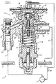
- the valve 10 includes a valve body 12 having an upper portion 14 with diaphragm assembly 16 threadedly connected to the upper end and a superheat spring assembly 18 at the lower end.
- the valve body upper portion 14 includes an inlet fitting 20 having a sweated connection 22, a filter assembly 24 and an inlet passage including a vertical passage 25, an inclined passage 26 leading to an axial piston passage 28 having a piston port 30 at the lower end communicating with a valve chamber 32 having an upper wall 33 defining the piston port 30.
- the upper portion 14 also includes an outlet fitting 34 having a sweated connection 36 and an outlet passage 38 communicating with the valve chamber 32.
- the valve body upper portion 14 also includes an equalization passage 39 as will be discussed below.
- a piston 40 is movably mounted in the piston passage 28 and said passage is sized to receive the piston upper end 42 in sliding relation.
- the piston passage 28 is grooved to receive a seal in the form of an O-ring 43 to prevent upward migration of refrigerant from the inclined passage 26.
- the piston lower end 44 is diametrically reduced in size to define a piston chamber 46 which communicates with the valve chamber 32 by way of the piston port 30.
- the valve body upper portion 14 is recessed to provide an abutment face 48, and the piston upper end includes a washer 50 held in place as by a snap ring to provide a retainer for a biasing spring 52 disposed between the abutment 48 and the washer 50 tending to urge the piston 40 upwardly. As best shown in FIG.
- the piston lower end is enlarged to provide a conical surface 54 which, under normal load conditions, is urged into a closed position relative to the piston port 30 by the biasing spring 52.
- the piston 40 includes an internal axial passage 60 having a valve pin port 62 communicating with the valve chamber 32 and transverse passages 64 communicating with the inclined inlet passage 26.
- valve pin 70 Flow of liquid refrigerant through the valve pin port 62 is controlled by a valve pin 70 which is mounted to a pin carrier 72 provided by a sliding retainer which receives a superheat spring 74.
- the spring 74 extends between the upper end of the pin carrier 72 and a sliding spring seat 76 which is adjusted by means of an adjustment screw 78 carried by a valve closure member 19 threadedly connected to the valve body 12.
- the superheat spring 74 tends to urge the valve pin 70 into the closed position and the valve pin tends to be urged into the open position in response to pressure on the diaphragm assembly 16.
- the diaphragm assembly 16 which constitutes a thermal responsive means, includes a diaphragm casing 80, a diaphragm 82 defining upper and lower chambers 81 and 83 and a bulb assembly 84 which is disposed in heat responsive relation to a selected part of the refrigerator system, for example to the outlet of the evaporator 3.
- the diaphragm assembly 16 includes a buffer plate 86 which is connected to the valve pin carrier 72 by a pair of pushrods 90. The buffer plate 86 is also engageable with the upper end of the piston 40 and, when the diaphragm pressure is sufficiently high, can exert sufficient force on the piston 40 to open the piston port 30.
- the buffer plate 86 includes an annular abutment portion 88 and the diaphragm casing 80 includes an interior annular abutment 92, constituting a stop means, with which the buffer plate portion 88 is engageable to limit travel of the piston 40. Also, in the embodiment shown, the lower diaphragm chamber 83 and the valve chamber 32 are connected by the equalization passage 39.
- the bulb temperature responds to the temperature of the evaporator outlet and the pressure on the diaphragm 80 moves the diaphragm and, by virtue of the buffer plate 86, the pushrods 90 and the pin carrier 72, this diaphragm movement moves the pin 70 relative to the valve port 62 at the lower end of the piston 40.
- this normal flow condition there is insufficient pressure on the piston 40 to overcome the upward force exerted by the piston spring 52 which therefore urges the piston into the closed position shown in FIG. 2.
- the piston acts as though it were part of the valve body 12 and refrigerant flow depends only on the stroke of the valve pin. As illustrated graphically in FIG. 5 flow during the first 0.025 inches (0.635mm)of stroke follows a relatively even, low curve.
- FIGs. 3 and 4 illustrate that under high temperature conditions, such as occur during pulldown, a radical change occurs.
- the pressure on the diaphragm 80 is sufficient to overcome the upward force of the spring 52 with the result that the piston 40 moves away from the piston port 30 so that the piston chamber 46 communicates directly with the valve chamber 32 and offers a secondary flow path and an additional annular area provided by the piston port 30 to that provided by the valve pin port 62.
- the flow during this operation increases dramatically as shown by the high curve in FIG. 5.
- flow increase for the first seventy percent (0.025 inches) (0.635 mm) of stroke is from 0 to 2.5 pounds (0-1.14 kg) of refrigerant per minute.
- valve provides for a flow increase of some three hundred percent for a forty percent increase in stroke.
- the seal 43 also acts to balance the piston 40 so that the forces created by the pressure drop from the high pressure side of the system (P1) to the low side of the system (P2) does not affect the position of the piston port 30.
- the pressure (P2) is communicated from the valve chamber 32 to the lower diaphragm chamber 83 by the equalization passage 39.
- the piston port 30 can be opened only by a force acting from the diaphragm 82 through the buffer plate 86. Contact between the buffer plate 86 and the piston 40 is maintained by the piston spring 52.
- valve pin 70 closes and there is no refrigerant flow through the valve port 62 or the piston port 30 and the expansion valve is effectively shut off.
- FIGs. 6-10 A modified valve 10a is illustrated in FIGs. 6-10 which is identical to the valve 10 described above except that the piston is provided with a cylindrical bleed control member 100. Since the valve is unchanged except for the modified lower end of the piston, identical parts are given the same number and similar parts are given the same number with the addition of the suffix "a".
- the piston 40a is coaxially recessed at its lower end 44a to provide the axial passage 60a with an enlarged lower passage portion 102 receiving the bleed control member 100 in sliding relation and an intermediate passage portion 104 communicating between the upper portion of the axial passage 60a and the lower passage portion 102 and defining an intermediate bleed port 106.
- the lower passage portion 102 is grooved to receive a machined ring 108, of brass or similar material, held in place as by coining and providing an abutment, and the lower passage portion 102 communicates with the valve chamber 32 by means of transverse passages 110.
- the bleed control member 100 includes an axial passage 112 communicating with the axial passage 60a at the upper end and defining a conical port 114 at the lower end receiving the valve pin 70.
- the bleed control member 100 includes a conical surface 116 at the upper end engageable with the bleed port 106 and a flat annular surface 118 at the lower end engageable with the ring 108.
- the longitudinal distance between the point of engagement of the bleed port 106 with the bleed control member conical surface 116 and the ring 108 is greater than the length of the bleed control member measured from its point of engagement with the bleed port 106 to its lower end surface 118 to provide said bleed control member with a stroke indicated by Sb .
- valve 10a The operation of the valve 10a is similar to that of the valve 10 except that under both normal flow and overload conditions there is a constant bleed flow through the valve.
- the valve pin 70 closes and the bleed control member 100 closes, as a result of the upward pressure from the superheat spring 74, and there is no refrigerant flow through the valve pin port 62, the bleed port 106 or the piston port 30 and the valve is effectively cut off.
- the bleed control member 100 acts as a pin closing the bleed port 106.
- the pushrods 90 begin to move the valve pin 70 downwardly.
- the bleed control member 100 follows the valve pin 70 until the bleed control member bottoms out against the ring 108. In this position, a bleed path is created through the bleed port 106 and the transverse passages 110, as shown by the arrows in FIG. 7, leading to the valve chamber 32 and communicating with the outlet passage 38. In effect, the bleed control member 100 cooperates with the bleed port 106 and the transverse passages 110 to provide a bleed means for the valve under operating conditions.
- the piston port 30 opens providing overload flow through the piston port 30, in addition to the holding load flow through the valve port 62, and in addition to the fixed flow through the bleed port 106, as shown in FIG. 9.
- the flow curve for the modified valve is shown in FIG. 10 which, for purposes of comparison also shows in phantom outline the curve from FIG. 5.
- the bleed occurs during the first 0.0035 inches (0.089 mm) of stroke (Sb); the holding load flow occurs from 0.0035 inches (0.089 mm) to 0.025 inches (0.635 mm) of stroke and the overload flow occurs from 0.025 inches (0.635 mm) to 0.035 inches (0.889 mm) of stroke.
- the bleed flow provides a fixed flow during normal and overload operating conditions but is cut off when the valve port 62 and piston port 30 are closed.
- FIG. 10 shows in phantom outline the curve from FIG. 5.
- the bleed flow increases from 0 to 2.0 pounds (0 - 0.91 kg) of refrigerant per minute for the first ten percent (0.0035 inches) (0.089 mm) of stroke; from 2.0 to 5.0 pounds (0.91 - 2.27 kg) of refrigerant per minute for the next sixty-two percent (0.0215 inches) (0.546 mm) of stroke and from 5.0 to 12.0 pounds (2.27 - 5.45 kg) of refrigerant per minute for the final twenty-eight percent (0.010 inches) (0.254 mm) of stroke.
- the bleed rate is a function of the port size, the angle of the bleed control member and the stroke and can be calculated by adjusting these elements.
- FIG. 5 depicts a flow curve with a maximum holding flow in the 2.5 pounds (1.136 kg) of refrigerant per minute range with a maximum pulldown load of 10.0 pounds (4.55 kg) per minute.
- FIG. 10 depicts a flow curve with a maximum holding flow in the 5 pounds (2.27 kg) of refrigerant per minute range with a maximum pulldown load of 12 pounds (5.45 kg) per minute and the structure of the bleed control member provides that there is no bleed when the valve is cut off.
- the bleed flow effectively allows the same holding load flow curve slope to be the same regardless of the actual holding load flow. By varying only the bleed rate a series of flow curves is generated.
- a possible alternative to the bleed control system described herein is to incorporate a permanent flow bleed into the valve fixed at say 2 pounds (0.91 kg) of refrigerant per minute.
Landscapes
- Physics & Mathematics (AREA)
- Engineering & Computer Science (AREA)
- Fluid Mechanics (AREA)
- Mechanical Engineering (AREA)
- Thermal Sciences (AREA)
- General Engineering & Computer Science (AREA)
- Temperature-Responsive Valves (AREA)
Claims (16)
- Expansionsventil (10) für ein Kühlsystem, wobei das Expansionsventil folgende Komponenten aufweist: einen Einlaß (20) für die Aufnahme eines Kältemittels von einem Kondensator (4) und einen Auslaß (34) für die Abgabe des Kältemittels an einen Verdampfer (3), und Steuermittel (16, 40, 70), die auf ein Signal von einem Temperaturmeßfühler (84) ansprechen, um den Fluß des Kältemittels durch das Ventil (10) zu steuern, wobei die Steuermittel (16, 40, 70) eine erste Öffnung (62) haben, die sich öffnen kann, um den Durchfluß des Kältemittels in Reaktion auf ein Signal in einem ersten, unteren Bereich des Temperaturmeßfühlers (84) zu erlauben, dadurch gekennzeichnet, daß die Steuermittel (16, 40, 70) eine zweite Öffnung (30) einschließen, die sich zusätzlich zu der ersten Öffnung öffnen kann, um den Durchfluß des Kältemittels in Reaktion auf ein Signal in einem zweiten, höheren Bereich des Temperaturmeßfühlers (84) zu erlauben.
- Expansionsventil nach Anspruch 1, gekennzeichnet durchein Ventilgehäuse (12), ein Einlaßdurchgangsmittel (25, 26), um bei der Nutzung ein Kältemittel aufzunehmen, wobei der Auslaß (34) Auslaßdurchgangsmittel (38) aufweist, um bei der Nutzung das Kältemittel abzugeben, wobei der Einlaß (20) ersten Durchgangsmittel (28) aufweist die Verbindung zwischen den Einlaßdurchgangsmitteln (25, 26) und den Auslaßdurchgangsmitteln (38) herstellen und die zweite Öffnung (30) definieren,wobei die Steuermittel (16, 40, 70) folgendes aufweisen:erste bewegliche Mittel (40), die in den ersten Durchgangsmitteln (28) angebracht sind und selektiv den Fluß durch die zweite Öffnung (30) in Reaktion auf das Signal im zweiten, höheren Temperaturbereich steuern,und die ersten beweglichen Mittel (40) zweite Durchgangsmittel (60) einschließen, welche die Verbindung zwischen den Einlaßdurchgangsmitteln (25, 26) und den Auslaßdurchgangsmitteln (38) herstellen und die erste Öffnung (62) definieren, wobei die zweiten beweglichen Mittel (70) in dem Ventilgehäuse (12) angebracht sind und selektiv den Fluß durch die zweiten Durchgangsmittel (60) in Reaktion aufdas Signal im ersten, unteren Temperaturbereich steuern,wobei der Temperaturmeßfühler auf die Temperatur ansprechende Mittel (84, 16) aufweist, welche die Bewegung der ersten beweglichen Mittel (40) und der zweiten beweglichen Mittel (70) steuern.
- Expansionsventil nach Anspruch 2, dadurch gekennzeichnet, daßdie ersten beweglichen Mittel (40) Kolbenmittel (40) sind und die ersten Durchgangsmittel (28) einen Kolbenschlitz (30) einschließen und daß die zweiten Durchgangsmittel (60) einen inneren Durchgang (60) durch den Kolben (40) und eine Stiftöfffnung (62, 114) einschließen und die zweiten beweglichen Mittel (70) Ventilstiftmittel (70) einschließen.
- Expansionsventil nach Anspruch 3, dadurch gekennzeichnet, daßdie Kolbenmittel (40) Mittel (52) einschließen, welche die Kolbenmittel in eine geschlossene Position vorspannen, und die Ventilstiftmittel (70) Mittel (74) einschließen, welche die Stiftmittel (70) in eine geschlossene Position vorspannen.
- Expansionsventil nach Anspruch 4, dadurch gekennzeichnet, daßdie auf die Temperatur ansprechenden Mittel (16) an einem Ende des Ventilgehäuses (12) angebracht sind,Mittel (90) vorhanden sind, welche die auf die Temperatur ansprechenden Mittel (16) mit den Ventilstiftmitteln (70) verbinden, die dazu tendieren, die Stiftmittel (70) unter normalen Lastbedingungen in eine offene Position zu bewegen, undMittel (86) vorhanden sind, welche die auf die Temperatur ansprechenden Mittel (16) mit den Kolbenmitteln (40) verbinden, die dazu tendieren, die Kolbenmittel (40) unter Überlastbedingungen in die offene Position zu bewegen.
- Expansionsventil nach Anspruch 5, dadurch gekennzeichnet, daßdas Ventilgehäuse (12) ein Widerlager (48) einschließt und die Kolbenmittel (40) ein erstes Ende (42), das mit Zwischenraum zum Widerlager (48) angeordnet ist, und ein zweites Ende (44) einschließen, das mit dem Kolbenschlitz (30) ineinandergreifen kann, unddie Kolbenvorspannmittel (52) Federmittel (52) zwischen dem Widerlager (48) und dem ersten Ende (42) der Kolbenmittel (40) einschließen, die dazu tendieren, das zweite Ende (44) der Kolbenmittel (40) in die mit dem Kolbenschlitz geschlossene Position zu drucken.
- Expansionsventil nach Anspruch 5 oder 6, dadurch gekennzeichnet, daßdie ersten Durchgangsmittel ein Axialdurchgang (28) mit einem oberen Ende und einem unteren Ende sind unddie Kolbenmittel (40) ein oberes Ende (42), das in einem Gleitverhältnis im oberen Ende des Axialdurchgangs (28) aufgenommen wird, und ein unteres Ende (44) einschließen, das diametral mit Zwischenraum zum unteren Ende des Axialdurchgangs (28) angeordnet ist, um eine Kolbenkammer (46) zu definieren.
- Expansionsventil nach Anspruch 7, dadurch gekennzeichnet, daßzwischen dem oberen Ende (42) der Kolbenmittel (40) und dem oberen Ende des Axialdurchgangs (28) eine Ringdichtung (43) bereitgestellt wird.
- Expansionsventil nach einem der Ansprüche 5 bis 8, dadurch gekennzeichnet, daßdie auf die Temperatur ansprechenden Mittel (16) Membranmittel (82) einschließen unddie Mittel (90), welche die auf die Temperatur ansprechenden Mittel (16) mit den Stiftmitteln (70) verbinden, Ventilstößelmittel (90) einschließen, die sich zwischen den Membranmitteln (82) und den Stiftmitteln (70) erstrecken.
- Expansionsventil nach einem der Ansprüche 5 bis 8, dadurch gekennzeichnet, daßdie auf die Temperatur ansprechenden Mittel (16) Membranmittel (82) einschließen, die Kolbenmittel (40) ein oberes Ende (42) einschließen und die Mittel (86), welche die auf die Temperatur ansprechenden Mittel (16) mit den Kolbenmitteln (40) verbinden, eine Pufferplatte (86) einschließen, die selektiv mit dem oberen Ende (42) der Kolbenmittel (40) ineinandergreifen kann.
- Expansionsventil nach Anspruch 10, dadurch gekennzeichnet, daßdas Ventilgehäuse (12) Anschlagmittel (92) einschließt und die Pufferplatte (86) mit den Anschlagmitteln (92) ineinandergreifen kann, um die Bewegung der Kolbenmittel (40) zu begrenzen.
- Expansionsventil nach einem der Ansprüche 5 bis 11, dadurch gekennzeichnet, daßdas Ventil (10) Ablaßmittel (100) einschließt, die den Fluß zwischen dem Einlaßdurchgang (26) und dem Auslaßdurchgang (38) zulassen.
- Expansionsventil nach einem der Ansprüche 5 bis 11, dadurch gekennzeichnet, daßdie Kolbenmittel (40) Ablaßsteuermittel (100) einschließen, die während des Betriebs den Fluß zwischen dem Einlaßdurchgang (26) und dem Auslaßdurchgang (38) zulassen und den Fluß zwischen dem Einlaßdurchgang (26) und dem Auslaßdurchgang (38) ausschließen, wenn das Ventil (10) geschlossen ist.
- Expansionsventil nach einem der Ansprüche 5 bis 11, dadurch gekennzeichnet, daßdie Kolbenmittel (40) folgendes einschließen: einen inneren Durchgang (112), der eine Ablaßöffnung (106) definiert, und ein Widerlager (108), das in Längsrichtung in einem Abstandsverhältnis zur Ablaßöffnung (106) angeordnet ist, und ein Ablaßsteuerelement (100), das ein oberes Ende (104), das funktionell mit der Ablaßöffnung (106) ineinandergreifen kann, und ein unteres Ende (108) hat, das funktionell mit dem Widerlager (108) ineinandergreifen kann und zur Bewegung in dem Durchgang zwischen der Ablaßöffnung (106) und dem Widerlager (108) angebracht ist, wobei das Ablaßsteuerelement (100) einen Durchgang einschließt, der die Ventilstiftöffnung (114) bereitstellt.
- Expansionsventil nach Anspruch 14, dadurch gekennzeichnet, daßder Längsabstand zwischen der Eingriffsstelle der Ablaßöffnung (106) und des Ablaßsteuerelements (100) und dem Widerlager (108) größer als die Länge des Ablaßsteuerelements (100) ist, gemessen von dessen Eingriffsstelle mit der Ablaßöffnung (106) bis zu dessen Eingriffsstelle mit dem Widerlager (108), um den Takt des Ablaßsteuerelements (100) zu definieren.
- Expansionsventil nach Anspruch 14 oder 15, dadurch gekennzeichnet, daßdas Widerlager durch einen kreisförmigen Ring (108) bereitgestellt wird.
Applications Claiming Priority (4)
| Application Number | Priority Date | Filing Date | Title |
|---|---|---|---|
| US57935 | 1987-06-03 | ||
| US992706 | 1992-12-18 | ||
| US07/992,706 US5277364A (en) | 1992-12-18 | 1992-12-18 | Dual capacity thermal expansion valve |
| US08/057,935 US5423480A (en) | 1992-12-18 | 1993-05-07 | Dual capacity thermal expansion valve |
Publications (2)
| Publication Number | Publication Date |
|---|---|
| EP0602996A1 EP0602996A1 (de) | 1994-06-22 |
| EP0602996B1 true EP0602996B1 (de) | 2000-05-17 |
Family
ID=26737049
Family Applications (1)
| Application Number | Title | Priority Date | Filing Date |
|---|---|---|---|
| EP93310230A Expired - Lifetime EP0602996B1 (de) | 1992-12-18 | 1993-12-17 | Thermisches Expansionsventil mit zwei Strömungsleistungen |
Country Status (4)
| Country | Link |
|---|---|
| US (1) | US5423480A (de) |
| EP (1) | EP0602996B1 (de) |
| DE (1) | DE69328663T2 (de) |
| DK (1) | DK0602996T3 (de) |
Families Citing this family (16)
| Publication number | Priority date | Publication date | Assignee | Title |
|---|---|---|---|---|
| NL1004208C2 (nl) * | 1996-10-04 | 1998-04-07 | Imperator Engineering & Consul | Koelinrichting van het type met een kringloop van koelfluïdum en werkwijze voor het bedrijven daarvan. |
| CA2272181A1 (en) * | 1998-06-01 | 1999-12-01 | Robert J. Torrence | Right angle thermally responsive expansion valve |
| US6314747B1 (en) | 1999-01-12 | 2001-11-13 | Xdx, Llc | Vapor compression system and method |
| ATE366397T1 (de) | 1999-01-12 | 2007-07-15 | Xdx Technology Llc | Dampfkompressionssystem und verfahren |
| US6185958B1 (en) | 1999-11-02 | 2001-02-13 | Xdx, Llc | Vapor compression system and method |
| AU759727B2 (en) | 1999-01-12 | 2003-04-17 | Xdx Inc. | Vapor compression system and method |
| JP2001033123A (ja) | 1999-07-19 | 2001-02-09 | Fuji Koki Corp | 温度膨張弁 |
| US6321995B1 (en) * | 1999-10-21 | 2001-11-27 | Parker-Hannifin Corporation | Thermostatic expansion valve |
| HK1048658B (en) * | 1999-11-02 | 2008-01-25 | Xdx Technology, Llc | Vapor compression system and method for controlling conditions in ambient surroundings |
| US6915648B2 (en) * | 2000-09-14 | 2005-07-12 | Xdx Inc. | Vapor compression systems, expansion devices, flow-regulating members, and vehicles, and methods for using vapor compression systems |
| US6393851B1 (en) | 2000-09-14 | 2002-05-28 | Xdx, Llc | Vapor compression system |
| US6401470B1 (en) | 2000-09-14 | 2002-06-11 | Xdx, Llc | Expansion device for vapor compression system |
| US6857281B2 (en) | 2000-09-14 | 2005-02-22 | Xdx, Llc | Expansion device for vapor compression system |
| DE10048816C2 (de) * | 2000-09-29 | 2002-10-24 | Danfoss As | Druckregelventil für eine Kälteanlage |
| CN100373079C (zh) * | 2005-01-12 | 2008-03-05 | 浙江三花制冷集团有限公司 | 双向流通热力膨胀阀 |
| CN104676992B (zh) | 2008-05-15 | 2017-07-11 | Xdx创新制冷有限公司 | 减少除霜的浪涌式蒸汽压缩传热系统 |
Family Cites Families (18)
| Publication number | Priority date | Publication date | Assignee | Title |
|---|---|---|---|---|
| US3252297A (en) * | 1963-08-27 | 1966-05-24 | Sporlan Valve Co | Thermostatic expansion valve with an auxiliary port |
| US3352125A (en) * | 1965-08-16 | 1967-11-14 | Gen Motors Corp | Pressure compensated polyphase expansion valve refrigeration system |
| US3699778A (en) * | 1971-03-29 | 1972-10-24 | Controls Co Of America | Thermal expansion valve with rapid pressure equalizer |
| US3875757A (en) * | 1972-01-19 | 1975-04-08 | Saginomiya Seisakusho Inc | Expansion valve for preventing hunting in refrigeration system |
| US3817053A (en) * | 1972-11-10 | 1974-06-18 | Controls Co Of America | Refrigerating system including flow control valve |
| US3807432A (en) * | 1972-11-14 | 1974-04-30 | R Cain | Pressure relief valve for bicycle tires |
| JPS5740423B2 (de) * | 1973-01-24 | 1982-08-27 | ||
| DE2348207A1 (de) * | 1973-09-25 | 1975-04-17 | Siemens Ag | Thyristorsaeule |
| US3899897A (en) * | 1974-04-03 | 1975-08-19 | Ford Motor Co | By-pass suction throttling valve in a refrigeration system |
| GB1481473A (en) * | 1974-06-12 | 1977-07-27 | Waso Ltd | Vent valve |
| US4095742A (en) * | 1976-08-26 | 1978-06-20 | Virginia Chemicals Inc. | Balanced single port thermostatic expansion valve |
| DE2831733A1 (de) * | 1978-06-26 | 1980-01-03 | Landis & Gyr Ag | Zweistufen-gasventil |
| US4342421A (en) * | 1981-02-23 | 1982-08-03 | General Motors Corporation | Thermostatic expansion valve for a refrigeration system |
| US5177972A (en) * | 1983-12-27 | 1993-01-12 | Liebert Corporation | Energy efficient air conditioning system utilizing a variable speed compressor and integrally-related expansion valves |
| JPH0665945B2 (ja) * | 1984-09-12 | 1994-08-24 | 日本電装株式会社 | 冷凍装置用膨脹弁 |
| US4750334A (en) * | 1987-03-26 | 1988-06-14 | Sporlan Valve Company | Balanced thermostatic expansion valve for refrigeration systems |
| NO172410C (no) * | 1991-04-04 | 1993-07-14 | Covent As | Ventil for stroemmende medium i vaeskeform |
| US5277364A (en) * | 1992-12-18 | 1994-01-11 | Sporlan Valve Company | Dual capacity thermal expansion valve |
-
1993
- 1993-05-07 US US08/057,935 patent/US5423480A/en not_active Expired - Lifetime
- 1993-12-17 EP EP93310230A patent/EP0602996B1/de not_active Expired - Lifetime
- 1993-12-17 DK DK93310230T patent/DK0602996T3/da active
- 1993-12-17 DE DE69328663T patent/DE69328663T2/de not_active Expired - Lifetime
Also Published As
| Publication number | Publication date |
|---|---|
| DK0602996T3 (da) | 2000-08-07 |
| US5423480A (en) | 1995-06-13 |
| EP0602996A1 (de) | 1994-06-22 |
| DE69328663T2 (de) | 2001-01-11 |
| DE69328663D1 (de) | 2000-06-21 |
Similar Documents
| Publication | Publication Date | Title |
|---|---|---|
| EP0602996B1 (de) | Thermisches Expansionsventil mit zwei Strömungsleistungen | |
| EP1052463B1 (de) | Entspannungsventil | |
| US6568656B1 (en) | Flow control valve with lateral port balancing | |
| EP1039250B1 (de) | Kältekreislauf mit einer Umgehungsleitung | |
| US5005370A (en) | Thermal expansion valve | |
| JPS6186536A (ja) | 冷凍装置および環境制御装置 | |
| US3435626A (en) | Pressure control apparatus for refrigeration system | |
| US4442680A (en) | Pilot-operated pressure regulator valve | |
| US3099140A (en) | Refrigeration system and control | |
| US5277364A (en) | Dual capacity thermal expansion valve | |
| US3667247A (en) | Refrigeration system with evaporator outlet control valve | |
| US7036744B2 (en) | Solenoid valve-equipped expansion valve | |
| US4535805A (en) | Pilot operated valve with pressure relief | |
| US3817053A (en) | Refrigerating system including flow control valve | |
| US5460349A (en) | Expansion valve control element for air conditioning system | |
| US3855836A (en) | Device for controlling coolant pressure in evaporator | |
| US2475556A (en) | Refrigeration system, including valve controls | |
| US2463951A (en) | Refrigeration expansion valve | |
| US6209793B1 (en) | Thermostatic expansion valve in which a valve seat is movable in a flow direction of a refrigerant | |
| US5531077A (en) | Refrigerating system with auxiliary compressor-cooling device | |
| US4750334A (en) | Balanced thermostatic expansion valve for refrigeration systems | |
| US4890458A (en) | Refrigerating circuit for car air conditioning | |
| EP0351204B1 (de) | Kraftfahrzeugklimaanlage mit Regelvorrichtung | |
| US4934156A (en) | Evaporator pressure regulating valve controlled by an auxiliary force for a refrigerator installation | |
| US3886761A (en) | Thermostatically operated suction throttling valve |
Legal Events
| Date | Code | Title | Description |
|---|---|---|---|
| PUAI | Public reference made under article 153(3) epc to a published international application that has entered the european phase |
Free format text: ORIGINAL CODE: 0009012 |
|
| AK | Designated contracting states |
Kind code of ref document: A1 Designated state(s): DE DK FR GB |
|
| 17P | Request for examination filed |
Effective date: 19941209 |
|
| 17Q | First examination report despatched |
Effective date: 19951229 |
|
| GRAG | Despatch of communication of intention to grant |
Free format text: ORIGINAL CODE: EPIDOS AGRA |
|
| GRAG | Despatch of communication of intention to grant |
Free format text: ORIGINAL CODE: EPIDOS AGRA |
|
| GRAG | Despatch of communication of intention to grant |
Free format text: ORIGINAL CODE: EPIDOS AGRA |
|
| GRAH | Despatch of communication of intention to grant a patent |
Free format text: ORIGINAL CODE: EPIDOS IGRA |
|
| GRAH | Despatch of communication of intention to grant a patent |
Free format text: ORIGINAL CODE: EPIDOS IGRA |
|
| GRAA | (expected) grant |
Free format text: ORIGINAL CODE: 0009210 |
|
| AK | Designated contracting states |
Kind code of ref document: B1 Designated state(s): DE DK FR GB |
|
| REF | Corresponds to: |
Ref document number: 69328663 Country of ref document: DE Date of ref document: 20000621 |
|
| REG | Reference to a national code |
Ref country code: DK Ref legal event code: T3 |
|
| ET | Fr: translation filed | ||
| PLBE | No opposition filed within time limit |
Free format text: ORIGINAL CODE: 0009261 |
|
| STAA | Information on the status of an ep patent application or granted ep patent |
Free format text: STATUS: NO OPPOSITION FILED WITHIN TIME LIMIT |
|
| 26N | No opposition filed | ||
| REG | Reference to a national code |
Ref country code: GB Ref legal event code: IF02 |
|
| REG | Reference to a national code |
Ref country code: GB Ref legal event code: 732E |
|
| REG | Reference to a national code |
Ref country code: FR Ref legal event code: TP |
|
| PGFP | Annual fee paid to national office [announced via postgrant information from national office to epo] |
Ref country code: DK Payment date: 20121228 Year of fee payment: 20 |
|
| PGFP | Annual fee paid to national office [announced via postgrant information from national office to epo] |
Ref country code: GB Payment date: 20121227 Year of fee payment: 20 |
|
| PGFP | Annual fee paid to national office [announced via postgrant information from national office to epo] |
Ref country code: FR Payment date: 20130110 Year of fee payment: 20 |
|
| PGFP | Annual fee paid to national office [announced via postgrant information from national office to epo] |
Ref country code: DE Payment date: 20121231 Year of fee payment: 20 |
|
| REG | Reference to a national code |
Ref country code: DE Ref legal event code: R071 Ref document number: 69328663 Country of ref document: DE |
|
| REG | Reference to a national code |
Ref country code: DK Ref legal event code: EUP Effective date: 20131217 |
|
| REG | Reference to a national code |
Ref country code: GB Ref legal event code: PE20 Expiry date: 20131216 |
|
| PG25 | Lapsed in a contracting state [announced via postgrant information from national office to epo] |
Ref country code: DE Free format text: LAPSE BECAUSE OF EXPIRATION OF PROTECTION Effective date: 20131218 Ref country code: GB Free format text: LAPSE BECAUSE OF EXPIRATION OF PROTECTION Effective date: 20131216 |