EP0602998A2 - Kassettenladevorrichtung für Bandrekorder - Google Patents
Kassettenladevorrichtung für Bandrekorder Download PDFInfo
- Publication number
- EP0602998A2 EP0602998A2 EP93310232A EP93310232A EP0602998A2 EP 0602998 A2 EP0602998 A2 EP 0602998A2 EP 93310232 A EP93310232 A EP 93310232A EP 93310232 A EP93310232 A EP 93310232A EP 0602998 A2 EP0602998 A2 EP 0602998A2
- Authority
- EP
- European Patent Office
- Prior art keywords
- support
- cassette
- lever member
- tape
- main deck
- Prior art date
- Legal status (The legal status is an assumption and is not a legal conclusion. Google has not performed a legal analysis and makes no representation as to the accuracy of the status listed.)
- Granted
Links
Images


Classifications
-
- G—PHYSICS
- G11—INFORMATION STORAGE
- G11B—INFORMATION STORAGE BASED ON RELATIVE MOVEMENT BETWEEN RECORD CARRIER AND TRANSDUCER
- G11B15/00—Driving, starting or stopping record carriers of filamentary or web form; Driving both such record carriers and heads; Guiding such record carriers or containers therefor; Control thereof; Control of operating function
- G11B15/675—Guiding containers, e.g. loading, ejecting cassettes
- G11B15/67563—Guiding containers, e.g. loading, ejecting cassettes with movement of the cassette perpendicular to its main side, i.e. top loading
- G11B15/67565—Guiding containers, e.g. loading, ejecting cassettes with movement of the cassette perpendicular to its main side, i.e. top loading of the cassette with holder
Definitions
- the present invention relates to tape recorders, and more particularly to loading and ejecting cassettes therefrom.
- tape recorder In the context of this specification, the term “tape recorder” is used in its popular sense of including devices for recording onto and/or replaying from magnetic tapes.
- various components of tape recorders required for recording signals on a tape or reproducing the recorded signals therefrom are positioned on either one deck, or a sub-deck and a main deck.
- installation on one deck has a problem in that it is impossible to make a product small since all of the components should be positioned on one deck and, therefore, the deck size itself tends to be increased.
- a recent tape recorder has components that are more dispersed by using, instead of a single deck, a sub-deck and a main deck, in order to minimize product size.
- this kind of tape recorder has a limitation in minimizing the size of the product itself, since the sub-deck moves on the main deck by a predetermined distance during operation.
- such a tape recorder must use a separate driving motor when loading and ejecting the cassette tape.
- the present applicant has proposed a tape recorder which can be simplified with respect to its structure and minimized to be of pocket size, by loading and ejecting a tape on a drum positioned within a housing according to closing and opening a lever housing after a cassette tape is placed in the housing and the lever housing operated as a hinge on a main deck.
- the tape recorder as mentioned above may have problems in that a cassette tape can be safely mounted on the main deck only by pressing and closing the lever housing after primarily loading the cassette tape in the housing, and the tape should be completely loaded on the drum since the loading apparatus can be operated by a separate driving motor. That is, this tape recorder has drawbacks that its construction can be complicated and its structural operation may not be easy.
- Preferred embodiments of the present invention aim to provide a cassette loading mechanism of a tape recorder in which a cassette tape is successively loaded and ejected during operating a lever member in an up and down movement, thereby easily and smoothly operating the cassette loading mechanism using a simple construction.
- a cassette loading mechanism of a tape recorder for recording and/or reproducing signals on a tape transported along a predetermined path, the mechanism comprising: a main deck having a tape transport system; a lever member hingedly mounted on said main deck; a support arranged to be moved up and down on said main deck by means of said lever member; and a cassette holder arranged to move from side to side on said support: whereby, when said lever member is rotated up and down, a side gear mounted on said support is brought into meshing engagement with a rack gear positioned on said lever member, and said cassette holder positioned on said support is slidably moved by clutching means connected to said gear, thereby to allow loading and ejecting of a cassette tape.
- loading and ejecting operations and up and down operations of a cassette tape are sequentially performed on said support by operating said lever member so as to rotate up and down.
- slots are formed in one end of said main deck and said support, respectively, and receive first and second pins formed on said lever member.
- said clutching means comprises a sector gear installed on said support to pivot by means of a bevel gear coaxially formed with said side gear; and a slide lever which rotates in meshing engagement with said sector gear, one end of which has a slot which receives a pin positioned on said cassette holder.
- the directions of said slots formed in said main deck and said support are substantially at right angles to each other.
- a resilient force is applied to said sector gear by a torsion spring of which one end is secured to said support.
- a cassette loading mechanism for a tape recorder and/or player, the mechanism comprising: a deck; a support mounted for movement with respect to said deck; a tape cassette holder slidably mounted on said support; and a lever member mounted for pivotal movement between first and second positions and connected to said deck, support and cassette holder such that, during such pivotal movement, said cassette holder and support are caused to move such that the cassette holder is moved between a loading position in which a cassette may be loaded into or unloaded from said holder and a playing position in which a cassette loaded into said holder is ready for recording and/or playing.
- a mechanism as above may further comprise any one or more of the features disclosed in the accompanying specification, claims, abstract and/or drawings, in any combination.
- the invention extends to a tape recorder and/or player provided with a mechanism according to any of the preceding aspects of the invention.
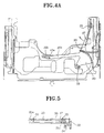
- the cassette loading mechanism shown schematically in Figures 1 to 4 includes a main deck 10 having various components such as a reel (not shown) required for tape transport, a lever member (or lever*housing) 20 which is hinge-coupled to one side of the main deck 10 and pivots up and down, a housing 30 positioned between the main deck 10, the lever member 20 which pivots up and down, and a cassette holder 40 which moves horizontally (as seen in Figure 1) along the housing 30.
- a main deck 10 having various components such as a reel (not shown) required for tape transport, a lever member (or lever*housing) 20 which is hinge-coupled to one side of the main deck 10 and pivots up and down, a housing 30 positioned between the main deck 10, the lever member 20 which pivots up and down, and a cassette holder 40 which moves horizontally (as seen in Figure 1) along the housing 30.
- an upwardly projecting bracket 11 is positioned on one side of the main deck 10.
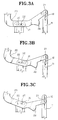
- a slot 12 of a small circular arc is formed in a vertical direction in the middle end of the bracket 11, and another slot 32 is formed in a horizontal direction in a bracket 31 formed on one side of the housing 30, so that first and second pins 21 and 22 respectively projecting on one side of the lever member 20 are inserted to be coupled with them, as shown in Figures 3A to 3C.
- a rack gear 23 is positioned on the end of the lever member 20 to be brought into meshing engagement with a side gear 33 mounted on the side of the housing 30.
- the cassette holder 40 positioned on the upper portion of the housing 30 is inwardly loaded or ejected by a clutch and interlocking device.
- the clutch operated by the side gear 33 mounted on the side of the housing 30 is brought into meshing engagement with a bevel gear 36a which is provided on a lower portion of a sector gear 36, meshes with a bevel gear 34 coaxially formed with the side gear 33, and rotates around the centre of a pin 35 on the housing 30.
- a torsion spring 37 cooperating with both the sector gear 36 and the housing 30 is mounted on the pin 35.
- a slide lever 39 which swings around a pin 38 on the housing 30 is brought into meshing engagement with the sector gear 36.
- a slot 39b is formed at the end of an arm 39a formed on one side of the slide lever 39 facing an approximate centre of the cassette loading mechanism, and a pin 40a projecting from the cassette holder 40 is inserted and fitted to the arm 39a.
- Slots 10b and 30b are formed in angle pieces 10a and 30a formed on the sides of the main deck 10 and the housing 30, respectively, so that first sides of respective first and second links 51 and 52 provided as an X-shape around an axis 50 are connected to respective angle pieces 10a and 30a. Other sides of the respective first and second links 51 and 52 are connected with the housing 30 and the main deck 10 so as to pivot, so that a predetermined elasticity is applied by means of the torsion spring 53.
- the housing 30 is elevated by resilience of the torsion spring 53 positioned at the first and second links 51 and 52 as a locking device (not shown) is released when the housing 30 is safely mounted to the main deck 10 as shown in Figure 2.
- the lever member 20 is raised by the angular amount ⁇ 1 due to the force exerted thereon, and would be raised further; but it cannot raise any more since the first pin 21 of the lever member 20 engages the end of the slot 12 of the main deck 10, and the second pin 22 of the lever member 20 is interlocked with the housing 30 to be continuously raised.
- the cassette holder 40 for housing the cassette tape is moved by a predetermined distance L as shown in broken line and, simultaneously, the cassette tape is easily ejected.
- the cassette tape when the cassette tape is to be safely mounted, the cassette tape is inserted into the cassette holder 40 and the lever member 20 is operated to move through ⁇ 2. By this operation, contrary to the process for ejecting, the cassette holder 40 is moved inwardly on the housing 30, thereby completing the loading. By descending further through ⁇ 2, the cassette tape can be safely mounted on the main deck 10.
- the illustrated cassette loading mechanism can be more smoothly and harmoniously operated without using a separate motor, by sequentially loading and ejecting the cassette tape while using the lever member which is opened and closed in a hinge manner.
Landscapes
- Automatic Tape Cassette Changers (AREA)
- Casings For Electric Apparatus (AREA)
- Adhesive Tape Dispensing Devices (AREA)
- Transmission Devices (AREA)
Applications Claiming Priority (4)
| Application Number | Priority Date | Filing Date | Title |
|---|---|---|---|
| KR1019920024590A KR0160620B1 (ko) | 1992-12-17 | 1992-12-17 | 테이프 레코더의 하우징 장치 |
| KR9224591 | 1992-12-17 | ||
| KR1019920024591A KR940016100A (ko) | 1992-12-17 | 1992-12-17 | 테이프 레코더의 하우징 장치 |
| KR9224590 | 1992-12-17 |
Publications (3)
| Publication Number | Publication Date |
|---|---|
| EP0602998A2 true EP0602998A2 (de) | 1994-06-22 |
| EP0602998A3 EP0602998A3 (de) | 1995-02-08 |
| EP0602998B1 EP0602998B1 (de) | 1999-02-24 |
Family
ID=26629433
Family Applications (1)
| Application Number | Title | Priority Date | Filing Date |
|---|---|---|---|
| EP93310232A Expired - Lifetime EP0602998B1 (de) | 1992-12-17 | 1993-12-17 | Kassettenladevorrichtung für Bandrekorder |
Country Status (8)
| Country | Link |
|---|---|
| US (1) | US5461522A (de) |
| EP (1) | EP0602998B1 (de) |
| JP (1) | JP3244896B2 (de) |
| CN (1) | CN1036427C (de) |
| CA (1) | CA2111659C (de) |
| DE (1) | DE69323605T2 (de) |
| ES (1) | ES2131101T3 (de) |
| RU (1) | RU2125742C1 (de) |
Cited By (1)
| Publication number | Priority date | Publication date | Assignee | Title |
|---|---|---|---|---|
| EP0986059A4 (de) * | 1998-03-16 | 2004-12-22 | Matsushita Electric Industrial Co Ltd | Magnetaufzeichnungs- und wiedergabegerät |
Family Cites Families (18)
| Publication number | Priority date | Publication date | Assignee | Title |
|---|---|---|---|---|
| JPH0831233B2 (ja) * | 1985-03-27 | 1996-03-27 | 株式会社日立製作所 | カセツト保持装置 |
| KR870003389Y1 (ko) * | 1985-06-28 | 1987-10-15 | 주식회사 금성사 | 비디오 테이프 레코오더의 카세트 하우징 |
| KR870006567A (ko) * | 1985-12-09 | 1987-07-13 | 허신구 | 카세트 홀더의 커버 연결장치 |
| JPS62250543A (ja) * | 1986-04-23 | 1987-10-31 | Hitachi Ltd | カセツト保持装置 |
| EP0260437B1 (de) * | 1986-08-19 | 1991-03-06 | Matsushita Electric Industrial Co., Ltd. | Kassettenladegerät |
| JPS63113856A (ja) * | 1986-10-30 | 1988-05-18 | Sony Corp | テ−プカセツト装着装置 |
| JP2565221B2 (ja) * | 1987-01-16 | 1996-12-18 | ソニー株式会社 | テ−ププレ−ヤ |
| JPS6442051A (en) * | 1987-08-07 | 1989-02-14 | Sharp Kk | Magnetic recording and reproducing device |
| JPS63249958A (ja) * | 1987-04-06 | 1988-10-17 | Sony Corp | カセツト装着装置 |
| JPH0198158A (ja) * | 1987-10-12 | 1989-04-17 | Hitachi Ltd | カセツト装着装置 |
| JPH0519867Y2 (de) * | 1987-12-15 | 1993-05-25 | ||
| CA1332757C (en) * | 1988-11-09 | 1994-10-25 | Takao Kumagai | Loading system for tape cassette in recording and/or reproducing apparatus |
| CA2009320C (en) * | 1989-02-18 | 1994-09-06 | Keiichi Ohashi | Cassette loading mechanism of a magnetic recording and reproducing apparatus |
| JP2644888B2 (ja) * | 1989-04-24 | 1997-08-25 | 株式会社日立製作所 | カセット装着装置 |
| JP2709138B2 (ja) * | 1989-05-02 | 1998-02-04 | キヤノン株式会社 | 記録再生装置 |
| US5175656A (en) * | 1989-11-07 | 1992-12-29 | Mitsubishi Denki Kabushiki Kaisha | Disk cartridge loadings/unloading system |
| JPH0449564A (ja) * | 1990-06-19 | 1992-02-18 | Matsushita Electric Ind Co Ltd | 磁気記録再生装置 |
| KR100188916B1 (ko) * | 1992-04-14 | 1999-06-01 | 윤종용 | 자기기록 재생장치 |
-
1993
- 1993-12-02 JP JP30306293A patent/JP3244896B2/ja not_active Expired - Fee Related
- 1993-12-16 RU RU93055871A patent/RU2125742C1/ru not_active IP Right Cessation
- 1993-12-16 CA CA002111659A patent/CA2111659C/en not_active Expired - Fee Related
- 1993-12-17 CN CN93112831A patent/CN1036427C/zh not_active Expired - Fee Related
- 1993-12-17 ES ES93310232T patent/ES2131101T3/es not_active Expired - Lifetime
- 1993-12-17 EP EP93310232A patent/EP0602998B1/de not_active Expired - Lifetime
- 1993-12-17 DE DE69323605T patent/DE69323605T2/de not_active Expired - Fee Related
- 1993-12-17 US US08/168,417 patent/US5461522A/en not_active Expired - Lifetime
Cited By (1)
| Publication number | Priority date | Publication date | Assignee | Title |
|---|---|---|---|---|
| EP0986059A4 (de) * | 1998-03-16 | 2004-12-22 | Matsushita Electric Industrial Co Ltd | Magnetaufzeichnungs- und wiedergabegerät |
Also Published As
| Publication number | Publication date |
|---|---|
| JP3244896B2 (ja) | 2002-01-07 |
| CA2111659C (en) | 2002-02-05 |
| ES2131101T3 (es) | 1999-07-16 |
| CN1088340A (zh) | 1994-06-22 |
| RU2125742C1 (ru) | 1999-01-27 |
| EP0602998A3 (de) | 1995-02-08 |
| DE69323605D1 (de) | 1999-04-01 |
| CN1036427C (zh) | 1997-11-12 |
| DE69323605T2 (de) | 1999-09-16 |
| US5461522A (en) | 1995-10-24 |
| CA2111659A1 (en) | 1994-06-18 |
| EP0602998B1 (de) | 1999-02-24 |
| JPH06215456A (ja) | 1994-08-05 |
Similar Documents
| Publication | Publication Date | Title |
|---|---|---|
| US4628383A (en) | Tape cassette loading device in a magnetic recording and/or reproducing apparatus | |
| CA1246213A (en) | Magnetic recording and reproducing apparatus | |
| US4816953A (en) | Tape cassette with groove engageable with loading hook | |
| GB2149187A (en) | Magnetic recording and reproducing apparatus | |
| JPH01159859A (ja) | Datのカセットローディング装置 | |
| US5345351A (en) | Pivoting device for a cover of the cassette holder of a magnetic-tape cassette apparatus | |
| US4301484A (en) | Cassette loading device of tape recorder | |
| EP0356184B1 (de) | Bandlademechanismus für ein magnetisches Aufnahme-/Wiedergabegerät für den selektiven Gebrauch mit Bandkassetten von zwei verschiedenen Grössen | |
| EP0637020B1 (de) | Aufzeichnungskassettenmechanismen | |
| EP0602998A2 (de) | Kassettenladevorrichtung für Bandrekorder | |
| KR0120540B1 (ko) | 테이프 레코더의 도어장치 | |
| US5430586A (en) | Tape extractor and pad lifter for extracting tape from a cassette center well, and related method | |
| WO1993021631A1 (en) | Subminiature recording and reproducing apparatus and method of operation thereof | |
| JP2625953B2 (ja) | テープ案内装置 | |
| KR940011547B1 (ko) | 카세트 적재기/비적재기 | |
| JP3547281B2 (ja) | ローディング機構及びそれを用いたディスク装置 | |
| US4159812A (en) | Apparatus for loading a tape cassette | |
| KR0160620B1 (ko) | 테이프 레코더의 하우징 장치 | |
| JPH0371465A (ja) | 磁気記録再生装置 | |
| JPH03283041A (ja) | Cdプレヤー付きカセットプレヤー | |
| EP0452007B1 (de) | Bandkassette mit Deckel | |
| KR0122989Y1 (ko) | 테이프 레코더의 카세트 리드개폐장치 | |
| KR0116647Y1 (ko) | 테이프 레코더의 슬라이더 하우징 록킹장치 | |
| JPS63273251A (ja) | テ−プレコ−ダ | |
| JPS61199264A (ja) | カセツトロ−デイング装置 |
Legal Events
| Date | Code | Title | Description |
|---|---|---|---|
| PUAI | Public reference made under article 153(3) epc to a published international application that has entered the european phase |
Free format text: ORIGINAL CODE: 0009012 |
|
| AK | Designated contracting states |
Kind code of ref document: A2 Designated state(s): DE ES FR GB |
|
| PUAL | Search report despatched |
Free format text: ORIGINAL CODE: 0009013 |
|
| AK | Designated contracting states |
Kind code of ref document: A3 Designated state(s): DE ES FR GB |
|
| 17P | Request for examination filed |
Effective date: 19950713 |
|
| 17Q | First examination report despatched |
Effective date: 19970704 |
|
| GRAG | Despatch of communication of intention to grant |
Free format text: ORIGINAL CODE: EPIDOS AGRA |
|
| GRAG | Despatch of communication of intention to grant |
Free format text: ORIGINAL CODE: EPIDOS AGRA |
|
| GRAH | Despatch of communication of intention to grant a patent |
Free format text: ORIGINAL CODE: EPIDOS IGRA |
|
| GRAH | Despatch of communication of intention to grant a patent |
Free format text: ORIGINAL CODE: EPIDOS IGRA |
|
| GRAA | (expected) grant |
Free format text: ORIGINAL CODE: 0009210 |
|
| AK | Designated contracting states |
Kind code of ref document: B1 Designated state(s): DE ES FR GB |
|
| REF | Corresponds to: |
Ref document number: 69323605 Country of ref document: DE Date of ref document: 19990401 |
|
| ET | Fr: translation filed | ||
| REG | Reference to a national code |
Ref country code: ES Ref legal event code: FG2A Ref document number: 2131101 Country of ref document: ES Kind code of ref document: T3 |
|
| PLBE | No opposition filed within time limit |
Free format text: ORIGINAL CODE: 0009261 |
|
| STAA | Information on the status of an ep patent application or granted ep patent |
Free format text: STATUS: NO OPPOSITION FILED WITHIN TIME LIMIT |
|
| 26N | No opposition filed | ||
| REG | Reference to a national code |
Ref country code: GB Ref legal event code: IF02 |
|
| PGFP | Annual fee paid to national office [announced via postgrant information from national office to epo] |
Ref country code: GB Payment date: 20071212 Year of fee payment: 15 Ref country code: FR Payment date: 20071210 Year of fee payment: 15 Ref country code: ES Payment date: 20080118 Year of fee payment: 15 |
|
| PGFP | Annual fee paid to national office [announced via postgrant information from national office to epo] |
Ref country code: DE Payment date: 20071213 Year of fee payment: 15 |
|
| GBPC | Gb: european patent ceased through non-payment of renewal fee |
Effective date: 20081217 |
|
| REG | Reference to a national code |
Ref country code: FR Ref legal event code: ST Effective date: 20090831 |
|
| PG25 | Lapsed in a contracting state [announced via postgrant information from national office to epo] |
Ref country code: DE Free format text: LAPSE BECAUSE OF NON-PAYMENT OF DUE FEES Effective date: 20090701 |
|
| PG25 | Lapsed in a contracting state [announced via postgrant information from national office to epo] |
Ref country code: GB Free format text: LAPSE BECAUSE OF NON-PAYMENT OF DUE FEES Effective date: 20081217 |
|
| REG | Reference to a national code |
Ref country code: ES Ref legal event code: FD2A Effective date: 20081218 |
|
| PG25 | Lapsed in a contracting state [announced via postgrant information from national office to epo] |
Ref country code: FR Free format text: LAPSE BECAUSE OF NON-PAYMENT OF DUE FEES Effective date: 20081231 Ref country code: ES Free format text: LAPSE BECAUSE OF NON-PAYMENT OF DUE FEES Effective date: 20081218 |