EP0603006A2 - Übertrageplatine für eine Flachstrickmaschine - Google Patents
Übertrageplatine für eine Flachstrickmaschine Download PDFInfo
- Publication number
- EP0603006A2 EP0603006A2 EP93310249A EP93310249A EP0603006A2 EP 0603006 A2 EP0603006 A2 EP 0603006A2 EP 93310249 A EP93310249 A EP 93310249A EP 93310249 A EP93310249 A EP 93310249A EP 0603006 A2 EP0603006 A2 EP 0603006A2
- Authority
- EP
- European Patent Office
- Prior art keywords
- stitch
- transferring
- jack
- needle
- knitting needle
- Prior art date
- Legal status (The legal status is an assumption and is not a legal conclusion. Google has not performed a legal analysis and makes no representation as to the accuracy of the status listed.)
- Granted
Links
Images


Classifications
-
- D—TEXTILES; PAPER
- D04—BRAIDING; LACE-MAKING; KNITTING; TRIMMINGS; NON-WOVEN FABRICS
- D04B—KNITTING
- D04B15/00—Details of, or auxiliary devices incorporated in, weft knitting machines, restricted to machines of this kind
- D04B15/02—Loop-transfer points
-
- D—TEXTILES; PAPER
- D04—BRAIDING; LACE-MAKING; KNITTING; TRIMMINGS; NON-WOVEN FABRICS
- D04B—KNITTING
- D04B15/00—Details of, or auxiliary devices incorporated in, weft knitting machines, restricted to machines of this kind
- D04B15/32—Cam systems or assemblies for operating knitting instruments
- D04B15/36—Cam systems or assemblies for operating knitting instruments for flat-bed knitting machines
- D04B15/362—Cam systems or assemblies for operating knitting instruments for flat-bed knitting machines with two needle beds in V-formation
- D04B15/365—Cam systems or assemblies for operating knitting instruments for flat-bed knitting machines with two needle beds in V-formation with provision for loop transfer from one needle bed to the other
-
- D—TEXTILES; PAPER
- D04—BRAIDING; LACE-MAKING; KNITTING; TRIMMINGS; NON-WOVEN FABRICS
- D04B—KNITTING
- D04B15/00—Details of, or auxiliary devices incorporated in, weft knitting machines, restricted to machines of this kind
- D04B15/66—Devices for determining or controlling patterns ; Program-control arrangements
- D04B15/68—Devices for determining or controlling patterns ; Program-control arrangements characterised by the knitting instruments used
- D04B15/78—Electrical devices
-
- D—TEXTILES; PAPER
- D04—BRAIDING; LACE-MAKING; KNITTING; TRIMMINGS; NON-WOVEN FABRICS
- D04B—KNITTING
- D04B7/00—Flat-bed knitting machines with independently-movable needles
- D04B7/24—Flat-bed knitting machines with independently-movable needles for producing patterned fabrics
- D04B7/28—Flat-bed knitting machines with independently-movable needles for producing patterned fabrics with stitch patterns
Definitions
- the present invention relates to an improvement of a transferring jack of a flat knitting machine.
- Japanese Examined Patent Publication No. 41-7907 discloses a flat knitting machine, wherein a pair of needles beds, containing movable knitting needles, are arranged to form an inverted V-shaped form in a side view.
- a transferring jack bed containing movable jacks in jack grooves, is provided above each needle bed.
- a stitch to be transferred is transferred from the knitting needle to the transferring jack, and the stitch engaged with the transferring jack is transferred to another knitting needle after the transferring jack engaged with the stitch is moved in a transverse direction.
- Japanese Unexamined Patent Publication No. 1-168943 discloses a flat knitting machine, wherein a transferring jack bed is supported above a needle bed by supporting members. Transferring jacks, at the front ends of which stitch engaging portions are formed, are movably arranged in the transferring bed. The transferring jacks are moved forward and backward by a transferring cam accompanied with a carriage. The transferring jack bed is moved in a transverse direction by a driving means provided at one side of the transferring jack bed. A stitch engaged with the stitch engaging portion is moved in a transverse direction and the stitch is transferred to another knitting needle.
- Japanese Examined Patent Publication No. 1-57173 discloses a flat knitting machine, wherein what is called "four beds" is formed by arranging a pair of front and rear needle beds upward and downward. A stitch is transferred by moving knitting needles in each of the needle beds and the stitch can be transferred in a transverse direction by moving each of the needle beds in such transverse direction.
- Japanese Examined Patent Publication No. 56-21854, of the present applicant, and Japanese Unexamined Patent Publication No. 63-256752 Discloses a flat knitting machine, wherein a transferring jack bed, containing movable jacks grooves, is provided above a needle bed. A stitch ti be transferred is transferred from the knitting needle to the transferring jack. The stitch engaged with the transferring jack is transferred to another knitting needle after the transferring jack engaged with the stitch is moved in a transverse direction.
- stitch engaging portions of the transferring jacks of the flat (weft) knitting machine described in the above publications are formed with jack bodies and plate members of elastic material, which are disposed along by one side of the jack bodies, and the stitch engaging portions elastically abut each other at the distal portions and are so arranged as to form stitch transferring apertures which allow the distal or tip portions of the knitting needles to enter in a plan view.
- the present invention avoids the above problems by ensuring that the distal part of the knitting needle enter through the stitch transferring aperture and that the stitch engaging portion of the transferring jack enter the stitch expanding portion of the knitting needle to allow the stitch to be transferred precisely.
- the present invention provides a transferring jack of a flat knitting machine having a knitting needle and a jack groove, comprising a jack body, a distal or tip end of the jack body forming a stitch engaging portion, the jack groove movably containing the transfer jack, a stitch transferring aperture formed at the stitch engaging portion, which allows the knitting needle to enter, at least one side of the stitch transferring aperture being formed, with an elastic plate, whereby the distal end is elastically closed and a guide face, formed at a bottom edge of the stitch transferring aperture, guides the knitting needle to enter the stitch transferring aperture.
- At least one side of members forming the stitch engaging portion may be formed with an elastic plate, at a distal end of a jack body of the transferring jack, and the guide face, which guides the knitting needle, may be formed by bending outward the elastic plate at a lower part of the stitch engaging portion.
- the guide face, which guides the knitting needle, may be formed by machining elastic plate at a lower part of at least one of members of the stitch engaging portion at a distal end of the jack body.
- a transferring jack of a flat knitting machine of the present invention having a knitting needle with a stitch expanding portion for transferring a stitch formed at one side of a body of the knitting needle, and having a transfer jack, a distal end of which forms a stitch engaging portion with a pair of plate materials facing each other, is characterized by forming a guide portion formed at base part of at least one of said stitch engaging portions of a plate material of said transferring jack facing the stitch expanding portion, which guides the stitch.
- the carriage As the carriage makes a round trip between a group of knitting needle for a predetermined width on the needle bed and knits a predetermined width, the carriage leads the needle selecting mechanism and operates a needle selecting portion of the transferring jack, to make a return trip between the edges of the predetermined width.
- a specific butt of the transferring jack is movably operated by a stitch transferring cam and a transferring stitch is engaged with a stitch engaging portion at a distal end of the transfer jack.
- the stitch engaged with the stitch engaging portion is transferred to a specific knitting needle after the transfer bed moves in a transverse direction through a supporting member.
- a stitch engaging portion is formed with a pair of plate facing each other, at the distal end of the jack body of the transferring jack, and a guide portion, for guiding a stitch is formed at a base part of the stitch engaging portion of the plate, facing the stitch expanding portion, out of the pair of the plates forming the stitch engaging portion, even if the trasferring jack is elastically deformed by a tension of the stitch engaged with the stitch engaging portion, or the stitch expanding portion is elastically deformed by a tension of the stitch expanded here, or shifted a little, the stitch engaging portion will smoothly enter the stitch expanding portion to result in a successful stitch transferring.
- Figure 1 is a schematic elevational view of a first embodiment of a flat knitting machine having a transferring mechanism.
- Figure 2 is a side view of Fig. 1
- Figure 3 is an enlarged cross-sectional side view of Fig. 2.
- the knitting machine 1 comprises a flat front lower needle bed 4A and a flat rear lower needle bed 4B which are arranged facing each other to form an inversed V-shaped form in a side view, and each transferring mechanism 5 arranged above each needle bed 4A, 4B respectively.
- a number of knitting needles 3A, 3B, Fig.3 are arranged, respectively, so as to be movable in needle grooves 77 by carriage 2A, 2B.
- the rear needle bed 4B is movable in transverse direction by a driving means which comprises a motor 6, a driving screw shaft 7, a slider 8, and the like (see Fig. 2).
- knitting needle 3A or 3B arranged in the needle groove 77 of the needle bed 4A or 4B comprises a knitting needle body 11 at the end of which a hook 10 is formed, a jack 12 which is connected to the rear end portion of the knitting needle body 11, a selecting jack 13 arranged at the rear portion of the jack 12, and a selector 14 arranged on the selecting jack 13. Butts 15A and 15B are projected upwardly from the jack 12, butt 16 is projected upwardly from the selector 14. When butts 15A, 15B, 16, and 17 move along a cam surface 76 of the carriages 2A, 2B, the jack 12, the selecting jack 13, and the selector 14 move in the needle groove 77.
- An expanding member 18 for expanding a loop retained by the knitting 3A or 3B and elasticity allowing portion and a spring portion 61 are arranged at a one side of the knitting needle body 11.
- the expanding member 18 is formed by bending sheet metal into a boat like shape, in plan view and the end of the expanding member 18 is fixed to the one side of the knitting needle body 11.
- group of cams of the carriages 2A and 2B over the needle beds 4A and 4B comprises two cam units arranged side by side.
- the cam unit comprises a transferring raising cam 20 protruded and retracted by a solenoid or a motor (not shown), a substantially trapezoid transferring receiving cam 21 arranged under the transferring raising cam 20, and can be protruded and retracted, needle raising cams 22 formed at the sides of the transferring receiving cams 21, and a convex portion 23 at the side of the needle raising cams 22.
- a needle selecting actuator 24 which acts on butts 17 of the selector 14 of the knitting needles 3A and 3B is arranged.
- a pressor mechanism 25 which acts the butt 16 of the selecting jack 13 of the knitting needles 3A and 3B so that the knitting needles 3A and 3B are located at the position for knitting, tucking, missing and transferring.
- Each transferring mechanism 5, arranged between carriage 2A and 2B, is supported by each of the flat transferring jack beds 27A, 27B (see Fig. 1 and Fig. 3).
- Each of the transferring jack beds 27A, 27B is supported by each supporting member 26 which is provided at each of the needle beds 4A, 4B via each slide mechanism 70.
- the transferring jack beds 27A and 27B are connected to each other at the end portions thereof by moving control bracket 71.
- Control bracket 71 is driven by a driving means 69 which comprises a motor 66, driving screw shaft 67, slider 68, and the like.
- a stitch engaged with the knitting needle 3A on the front needle bed 4A can be transferred to the knitting needle 3B on the rear needle bed 4B or to a transferring jack 29A or 29B (referred to hereinafter) on the transferring jack bed 27A or 27B of the transferring mechanism 5. Also a stitch engaged with the knitting needle 3B on the rear needle bed 4B can be transferred to the knitting needle 3A on the front needle bed 4A or to the transferring jack 29A or 29B on the transferring jack bed 27A or 27B of the transferring mechanism 5.
- jack grooves 72 in which the transferring jack 29A and 29B are movably positioned are formed.
- each transferring cam 31 and each needle selecting mechanism 30 for selecting the transferring jacks 29A and 29B are positioned.
- a hook shaped stitch engaging portion 32 is formed at the front end of the transferring jack 29A (29B), a needle selected member 33 is formed at the rear end of the transferring jack 29A (29B), and a curved portion 79 is formed at the jack body 34 side of the stitch engaging portion 32.
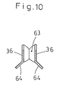
- a pair of plate materials 36 of narrow width of spring steel facing each other extrude, the middle parts of which are caulked 62 with the jack bodies 34 from the both right and left sides of the jack bodies 34.
- the distal portions of both of the plate materials 36 are bent inward to about each other and form a stitch transferring aperture 63.
- the distal portion forms a hook.
- a lower edge of the plate material 36 is bent outward, at a part of the stitch transferring aperture 63, and a guide face (guide part) 64 is formed inside, as shown in Fig. 10.
- the stitch engaging portion 32 is formed as a smoothly curved slope 88 at the base portion of the stitch engaging portion 32 with a shoulder part 89 to stop a stitch 52 at the base part of the stitch engaging portion 32 of the plate material 36 facing the knitting needle body 11 (see Fig 9).
- the guide face 64 can be formed by machining, as shown in Fig. 11, or can be formed by making the plate materials 36 broaded at a lower part, as shown in Fig. 12. Further, a base end side part of the plate material 36, facing a side of the jack body 34, is bent to form an elastic portion 37.
- the needle selected member 33 comprises a plate 38 with a length H, and a return butt 41 with which a return cam 42 (referred to hereinafter) acts.
- a groove with a width h, is formed and forms a needle selected butt 40.
- the position of the needle selected butt 40 in Fig. 6 is different from needle selected butt 40' in Fig. 8, that is, the needle selected butts 40 In Fig. 6 and the needle selected butt 40 in Fig. 8 have different phases. According to this difference, the position of the return butt 41 in Fig. 6 is also different from the return butt 41' in Fig. 8.
- Transferring jack groups are formed from a plurality of transferring jacks 29A (29B) having the same needle selected members 33 transferring jack groups of different selected members 33, 33' are arranged, alternatively, every 1 inch.
- the transferring cam 31 for acting the needle selected butt 40, 40' of the needle selected member 33, 33' as the case maybe and the return cam 42 for acting the return butt 41, 41' are arranged at the space between the carriage 2A (2B) on the needle bed 4A (4B) and a yarn guide arranged over an aperture between the needle beds 4A and 4B.
- the transferring cam 31 has a cam plate 44.
- a cam groove 43 with a width H is formed on the lower surface 44a of the cam plate 44 and the cam plate 44 protruded from the side portion of the carriage 2A (2B) so that the lower surface 44a of the cam plate 44 is slidable on the upper surface of the transferring jack bed 27A (27B).
- the return cam 42 for acting the return butt 47, 41' is fixed to a bracket 55 which is fixed to the side portion of the carriage 2A (2B).
- operation holes through which operating portion of an actuator 45 of a needle selecting means 30 for operating the needle selected butt 40 is provided.
- needle selecting means 30 comprises a solenoid 49, a swinging lever 50, supporting axis 51, and a needle selecting cam plate.
- the solenoid 49 is fixed to casing 48 which is fixed to the carriage 2A (2B).
- the solenoid 49 is connected to the one each of the swinging lever 50 and the other end thereof is fixed to the supporting axis 51.
- the needle selecting cam plate 47 which passes through the operation hole 46 and operates as the operating Portion of the actuator 45 is also fixed to the supporting axis 51.
- Different needle selecting means 30 are arranged in transferring jack bed 27a or 27b, respectively, corresponding to the transferring jacks 29A (29B) (see Figure 14 and Figure 15).
- the solenoid 49 of the needle selecting means 30 of the transferring mechanism 5 maintains the swinging lever 47 in a standing position and therefore the needle selected butt 40 which is in a waiting position is pushed downwardly not to by operated by the cam groove 43 of the cam plate 44 even though the carriage 2A (2B) moves.
- the needle selected butt 40 which is pushed downwardly in an unoperated position is returned to the waiting position again by the return cam 42.
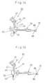
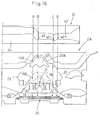
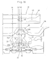
- Fig. 17A ??Fig. 17D and Fig. 19A ??Fig.19D designate the group of cams of the carriage 2A for moving the knitting needles 3A on the front needle bed 4A, and the cam groove 43 on the cam plate 44 for operating the transferring jacks 29B in the rear transferring jack bed 27B.
- the carriage 2A is moved on the needle bed 4A from right to left, the butts 15A and 15B of the jack 12 of the knitting needle 3 and the butt 16 of the selecting jack 13 of the knitting needle 3 pass in the group of cams of the carriage 2 from left to right as shown symbols A, B, C, and D in Fig. 16.
- the front knitting needle 3A When the front knitting needle 3A reaches the position C, as shown in Fig. 17C, the front knitting needle 3A is retracted gradually because the butt 15A of the jack 12 is gradually pushed downwardly, and the needle selected butt 40 of the transferring jack 29B is pushed outwardly by the cam groove 43 of the cam plate 44 so that the stitch 52 does not interfere with the latch 55 when the front knitting needle 3A retracts.
- the transferring jack 29B keeps the stitch 52 at the stitch engaging portion 32.
- the transferring jack bed 27B is moved transversely by predetermined pitches (for example one pitch) by the motor 66 via the driving screw shaft 67, the slider 68, and the move control bracket 71.
- predetermined pitches for example one pitch
- the trasferring jack bed 27B can be moved transverse direction without interfering with the sinker or the knitting needles 3A and 3B.
- the stitch engaging portion 32 is prevented from being deformed by tension of the stitch 52, as the transferring jack bed 27B is moving in a transverse direction, and the hook 10 of the knitting needle 3A, guided by the guide face 64, expands the stitch transferring aperture 63, even when the stitch transferring aperture 63 is narrowed, ensuring the knitting needle 3A to be insert into the stitch transferring aperture 63. Consequently stitch 52 can be successfully transferred.
- the knitting needle is a latch needle but, needless to say, the present invention can also be practiced with a compound needle.
- the number of types of butt for needle selection, constituting the needle selecting part of the above embodiment can be three or more for different phases against a sliding direction of a transfer jack.
- the stitch transferring aperture is formed by two plate materials but, needless to say, one or both of said plate materials can be formed by the jack bodies.
Landscapes
- Engineering & Computer Science (AREA)
- Textile Engineering (AREA)
- Knitting Machines (AREA)
Applications Claiming Priority (3)
| Application Number | Priority Date | Filing Date | Title |
|---|---|---|---|
| JP4337328A JP2604677B2 (ja) | 1992-12-17 | 1992-12-17 | 横編機におけるトランスファージャック |
| JP33732892 | 1992-12-17 | ||
| JP337328/92 | 1992-12-17 |
Publications (3)
| Publication Number | Publication Date |
|---|---|
| EP0603006A2 true EP0603006A2 (de) | 1994-06-22 |
| EP0603006A3 EP0603006A3 (en) | 1994-08-24 |
| EP0603006B1 EP0603006B1 (de) | 2000-04-12 |
Family
ID=18307594
Family Applications (1)
| Application Number | Title | Priority Date | Filing Date |
|---|---|---|---|
| EP93310249A Expired - Lifetime EP0603006B1 (de) | 1992-12-17 | 1993-12-17 | Übertrageplatine für eine Flachstrickmaschine |
Country Status (4)
| Country | Link |
|---|---|
| US (1) | US5423204A (de) |
| EP (1) | EP0603006B1 (de) |
| JP (1) | JP2604677B2 (de) |
| DE (1) | DE69328343T2 (de) |
Cited By (4)
| Publication number | Priority date | Publication date | Assignee | Title |
|---|---|---|---|---|
| EP0902111A3 (de) * | 1997-09-12 | 2000-04-26 | Shima Seiki Manufacturing, Ltd. | Flachstrickmaschine mit Maschendrücker und Verfahren zum Stricken mit dieser Flachstrickmaschine |
| EP0924327A3 (de) * | 1997-12-19 | 2000-05-31 | Shima Seiki Co., Ltd. | Flachstrickmaschine mit Umhängplatine-Umhängvorrichtung |
| EP0939158A3 (de) * | 1998-02-20 | 2000-09-06 | FABRITEX S.r.l | Vorrichtung zum Verlegen von Maschen von Textilwaren |
| RU2176295C2 (ru) * | 1998-02-20 | 2001-11-27 | Фабритекс С.р.л. | Устройство для переноса петель текстильных изделий (варианты) |
Families Citing this family (8)
| Publication number | Priority date | Publication date | Assignee | Title |
|---|---|---|---|---|
| US6047569A (en) * | 1997-05-27 | 2000-04-11 | Shima Seiki Manufacturing, Ltd. | Method for holding a stitch loop |
| US20040104845A1 (en) * | 1998-02-20 | 2004-06-03 | Tks, Inc. | System, Method, and Product for Derivative-Based Wagering Racing Application |
| JP2995464B2 (ja) * | 1998-05-15 | 1999-12-27 | 株式会社島精機製作所 | 横編機における編目ループの預け置き装置 |
| TW548358B (en) | 2000-08-22 | 2003-08-21 | Shima Seiki Mfg | Weft knitting machine with transfer mechanism and transferring method |
| EP1505185B1 (de) * | 2002-05-15 | 2014-04-23 | Shima Seiki Mfg., Ltd | Flachstrickmaschine mit übertragungselement und maschenübertragungsverfahren mit übertragungselement |
| FR2986242B1 (fr) * | 2012-01-26 | 2014-02-14 | Steiger Participations Sa | Procede de tricotage pour machine a tricoter rectiligne et machine a tricoter rectiligne |
| CN115832572B (zh) * | 2023-01-03 | 2023-08-25 | 南京农业大学 | 针对智能仓储设备电气部件的防护装置、电池组结构 |
| DE112024002441T5 (de) * | 2023-06-07 | 2026-03-19 | Shima Seiki Mfg., Ltd. | Flachstrickmaschine mit einem Umhängestößer sowie Umhängestößer |
Family Cites Families (13)
| Publication number | Priority date | Publication date | Assignee | Title |
|---|---|---|---|---|
| DE373863C (de) * | 1919-11-10 | 1923-04-17 | Ernest Desachy | Strickmaschine mit zwei Betten |
| DE432224C (de) * | 1924-09-11 | 1926-07-29 | Joh F A Schoening | Flachstrickmaschine zur Herstellung von schlauchfoermiger Wirkware |
| DE591171C (de) * | 1932-01-14 | 1934-01-17 | Schaffhauser Strickmaschf | Strickmaschine |
| US2401732A (en) * | 1944-04-13 | 1946-06-11 | Max Nydegger | Knitting machine |
| DE804339C (de) * | 1947-02-26 | 1951-04-19 | Albert Matthews Brown | Rundstrickmaschine |
| US2708355A (en) * | 1953-06-05 | 1955-05-17 | Willy Werner Lenkeit | Suspension comb for hand-operated knitting machines |
| CH420467A (de) * | 1963-12-23 | 1966-09-15 | Schieber Universal Maschf | Einrichtung zum Umhängen von Maschen von einer Nadel zur Nachbarnadel des gleichen Nadelbettes |
| CH431790A (de) * | 1964-07-22 | 1967-03-15 | Erba Maschinenbau Ag | Verfahren und Einrichtung zum Übertragen von Maschen in lateraler bzw. transversaler Richtung auf Handstrickmaschinen |
| JPS5621854B2 (de) * | 1973-12-28 | 1981-05-21 | ||
| SU950824A1 (ru) * | 1979-03-22 | 1982-08-15 | За витель | Петлепереносчик |
| IT1208272B (it) * | 1987-04-10 | 1989-06-12 | Martinelli Comet Srl | Apparato di trasporto laterale per le macchine rettilinee da maglieria |
| JPS6468547A (en) * | 1987-09-04 | 1989-03-14 | Shima Seiki Mfg | Traverse knitting machine |
| EP0310730A1 (de) * | 1987-10-05 | 1989-04-12 | José Abril Cullell | Flachstrickmaschinen |
-
1992
- 1992-12-17 JP JP4337328A patent/JP2604677B2/ja not_active Expired - Fee Related
-
1993
- 1993-12-16 US US08/166,994 patent/US5423204A/en not_active Expired - Lifetime
- 1993-12-17 DE DE69328343T patent/DE69328343T2/de not_active Expired - Lifetime
- 1993-12-17 EP EP93310249A patent/EP0603006B1/de not_active Expired - Lifetime
Cited By (5)
| Publication number | Priority date | Publication date | Assignee | Title |
|---|---|---|---|---|
| EP0902111A3 (de) * | 1997-09-12 | 2000-04-26 | Shima Seiki Manufacturing, Ltd. | Flachstrickmaschine mit Maschendrücker und Verfahren zum Stricken mit dieser Flachstrickmaschine |
| EP0924327A3 (de) * | 1997-12-19 | 2000-05-31 | Shima Seiki Co., Ltd. | Flachstrickmaschine mit Umhängplatine-Umhängvorrichtung |
| EP0939158A3 (de) * | 1998-02-20 | 2000-09-06 | FABRITEX S.r.l | Vorrichtung zum Verlegen von Maschen von Textilwaren |
| RU2176295C2 (ru) * | 1998-02-20 | 2001-11-27 | Фабритекс С.р.л. | Устройство для переноса петель текстильных изделий (варианты) |
| CZ298039B6 (cs) * | 1998-02-20 | 2007-05-30 | Fabritex S. R. L. | Úprava stahovace a prenosové soucásti pro príjem a prenos ocek textilního výrobku a prostredek pro podporu ocek |
Also Published As
| Publication number | Publication date |
|---|---|
| DE69328343D1 (de) | 2000-05-18 |
| EP0603006B1 (de) | 2000-04-12 |
| JP2604677B2 (ja) | 1997-04-30 |
| DE69328343T2 (de) | 2000-12-07 |
| JPH06257039A (ja) | 1994-09-13 |
| US5423204A (en) | 1995-06-13 |
| EP0603006A3 (en) | 1994-08-24 |
Similar Documents
| Publication | Publication Date | Title |
|---|---|---|
| EP0594169B1 (de) | Flachstrickmaschine mit Übertragevorrichtung | |
| US6079231A (en) | Stitch loop holding apparatus for a flat knitting machine | |
| US5423204A (en) | Transferring jack of a flat knitting machine | |
| KR101209644B1 (ko) | 횡편기의 선침장치 | |
| EP1437433B1 (de) | Flachstrickmaschine mit maschendrucker und entsprechendes strickverfahren | |
| EP0751248A1 (de) | Strick- und Umhängeschlossteil für Flachstrickmaschine | |
| EP1835059B1 (de) | Komplexes schlosssystem | |
| JP3408735B2 (ja) | トランスファージャック目移し機構を備えた横編機 | |
| KR101065245B1 (ko) | 편사의 지지절단 방법 및 장치 | |
| EP0603005B1 (de) | Flachstrickmaschine | |
| EP1655398A1 (de) | Kulierstrick- oder kulierwirkmaschine mit bewegbarer platine | |
| EP1942216B1 (de) | Flachstrickmaschine mit bewegbarem fadenführer | |
| EP0604164B1 (de) | Verfahren zum Stricken eines Kreuzmusters und Vorrichtung zum Stricken eines Kreuzmusters an einer Flachstrickmachine | |
| US6688140B2 (en) | Weft knitting machine with transfer mechanism and transferring method | |
| KR100768345B1 (ko) | 코 이동 기구를 구비하는 횡편기 | |
| EP3798339B1 (de) | Flachbettstrickmaschine |
Legal Events
| Date | Code | Title | Description |
|---|---|---|---|
| PUAI | Public reference made under article 153(3) epc to a published international application that has entered the european phase |
Free format text: ORIGINAL CODE: 0009012 |
|
| AK | Designated contracting states |
Kind code of ref document: A2 Designated state(s): CH DE ES FR GB IT LI |
|
| PUAL | Search report despatched |
Free format text: ORIGINAL CODE: 0009013 |
|
| AK | Designated contracting states |
Kind code of ref document: A3 Designated state(s): CH DE ES FR GB IT LI |
|
| 17P | Request for examination filed |
Effective date: 19950112 |
|
| 17Q | First examination report despatched |
Effective date: 19961125 |
|
| GRAG | Despatch of communication of intention to grant |
Free format text: ORIGINAL CODE: EPIDOS AGRA |
|
| GRAG | Despatch of communication of intention to grant |
Free format text: ORIGINAL CODE: EPIDOS AGRA |
|
| GRAH | Despatch of communication of intention to grant a patent |
Free format text: ORIGINAL CODE: EPIDOS IGRA |
|
| GRAH | Despatch of communication of intention to grant a patent |
Free format text: ORIGINAL CODE: EPIDOS IGRA |
|
| ITF | It: translation for a ep patent filed | ||
| GRAA | (expected) grant |
Free format text: ORIGINAL CODE: 0009210 |
|
| AK | Designated contracting states |
Kind code of ref document: B1 Designated state(s): CH DE ES FR GB IT LI |
|
| PG25 | Lapsed in a contracting state [announced via postgrant information from national office to epo] |
Ref country code: LI Free format text: LAPSE BECAUSE OF FAILURE TO SUBMIT A TRANSLATION OF THE DESCRIPTION OR TO PAY THE FEE WITHIN THE PRESCRIBED TIME-LIMIT Effective date: 20000412 Ref country code: ES Free format text: THE PATENT HAS BEEN ANNULLED BY A DECISION OF A NATIONAL AUTHORITY Effective date: 20000412 Ref country code: CH Free format text: LAPSE BECAUSE OF FAILURE TO SUBMIT A TRANSLATION OF THE DESCRIPTION OR TO PAY THE FEE WITHIN THE PRESCRIBED TIME-LIMIT Effective date: 20000412 |
|
| REG | Reference to a national code |
Ref country code: CH Ref legal event code: EP |
|
| REF | Corresponds to: |
Ref document number: 69328343 Country of ref document: DE Date of ref document: 20000518 |
|
| ET | Fr: translation filed | ||
| REG | Reference to a national code |
Ref country code: CH Ref legal event code: PL |
|
| PLBE | No opposition filed within time limit |
Free format text: ORIGINAL CODE: 0009261 |
|
| STAA | Information on the status of an ep patent application or granted ep patent |
Free format text: STATUS: NO OPPOSITION FILED WITHIN TIME LIMIT |
|
| 26N | No opposition filed | ||
| REG | Reference to a national code |
Ref country code: GB Ref legal event code: IF02 |
|
| PGFP | Annual fee paid to national office [announced via postgrant information from national office to epo] |
Ref country code: FR Payment date: 20101224 Year of fee payment: 18 |
|
| PGFP | Annual fee paid to national office [announced via postgrant information from national office to epo] |
Ref country code: GB Payment date: 20101215 Year of fee payment: 18 |
|
| GBPC | Gb: european patent ceased through non-payment of renewal fee |
Effective date: 20111217 |
|
| REG | Reference to a national code |
Ref country code: FR Ref legal event code: ST Effective date: 20120831 |
|
| PG25 | Lapsed in a contracting state [announced via postgrant information from national office to epo] |
Ref country code: GB Free format text: LAPSE BECAUSE OF NON-PAYMENT OF DUE FEES Effective date: 20111217 |
|
| PGFP | Annual fee paid to national office [announced via postgrant information from national office to epo] |
Ref country code: DE Payment date: 20121213 Year of fee payment: 20 |
|
| PGFP | Annual fee paid to national office [announced via postgrant information from national office to epo] |
Ref country code: IT Payment date: 20121214 Year of fee payment: 20 |
|
| PG25 | Lapsed in a contracting state [announced via postgrant information from national office to epo] |
Ref country code: FR Free format text: LAPSE BECAUSE OF NON-PAYMENT OF DUE FEES Effective date: 20120102 |
|
| REG | Reference to a national code |
Ref country code: DE Ref legal event code: R071 Ref document number: 69328343 Country of ref document: DE |
|
| REG | Reference to a national code |
Ref country code: DE Ref legal event code: R071 Ref document number: 69328343 Country of ref document: DE |
|
| PG25 | Lapsed in a contracting state [announced via postgrant information from national office to epo] |
Ref country code: DE Free format text: LAPSE BECAUSE OF EXPIRATION OF PROTECTION Effective date: 20131218 |