EP0603009A2 - Speiser - Google Patents
Speiser Download PDFInfo
- Publication number
- EP0603009A2 EP0603009A2 EP93310264A EP93310264A EP0603009A2 EP 0603009 A2 EP0603009 A2 EP 0603009A2 EP 93310264 A EP93310264 A EP 93310264A EP 93310264 A EP93310264 A EP 93310264A EP 0603009 A2 EP0603009 A2 EP 0603009A2
- Authority
- EP
- European Patent Office
- Prior art keywords
- molten glass
- weight
- passage
- gob
- neck portion
- Prior art date
- Legal status (The legal status is an assumption and is not a legal conclusion. Google has not performed a legal analysis and makes no representation as to the accuracy of the status listed.)
- Withdrawn
Links
Images

Classifications
-
- C—CHEMISTRY; METALLURGY
- C03—GLASS; MINERAL OR SLAG WOOL
- C03B—MANUFACTURE, SHAPING, OR SUPPLEMENTARY PROCESSES
- C03B7/00—Distributors for the molten glass; Means for taking-off charges of molten glass; Producing the gob, e.g. controlling the gob shape, weight or delivery tact
- C03B7/08—Feeder spouts, e.g. gob feeders
- C03B7/094—Means for heating, cooling or insulation
Definitions
- the present invention relates to machines such as I.S. (individual section) machines which receive discrete gobs of molten glass and form them into glass containers and, more specifically, to a spout bowl assembly which is used in connection with a feeder to feed gobs to the machine.
- I.S. individual section machines
- a spout bowl assembly which is used in connection with a feeder to feed gobs to the machine.
- the solid components of the glass batch are melted in a furnace and then passed through a forehearth which may consist of a rear or cooling section with means for both heating and cooling and a front section called the conditioning or equalizing section and which usually has means for heating only.
- a forehearth which may consist of a rear or cooling section with means for both heating and cooling and a front section called the conditioning or equalizing section and which usually has means for heating only.
- a spout and feeder mechanism which together cooperate to form the molten glass into gobs for delivery to the glass container forming machine.
- the forehearth along with the spout and feeder mechanism function to take the glass from a melting furnace at whatever temperature is best for glass making and to deliver it to the forming machine as a uniformly consistent gob having the desired weight, shape and temperature and at a speed suited to the article being fabricated.
- the spout itself usually contains heating elements to control the temperature of the contained molten glass. Such heating elements in the form of gas burners heating the air above the contained molten glass are shown in U.S. patents numbered 4,725,301, 2,990,649, 2,623,330 and 2,139,911.
- the bowl may be rotated or the spout bowl tube may be rotated or vorticular flow can be created by choosing an exit contour that will yield such flow. See, for example, U.S. patents 1,869,921 and 1,870,210.
- U.S. Patents numbered 4,682,998 and 4,708,729 suggest that gob weight can be controlled by controlling 1) the temperature, homogeneity and viscosity of the molten glass; 2) the level of glass in the feeder bowl; 3) the wear of the orifice hole(s); and 4) the motion of the movable structures, i.e. tube rotation, speed and stroke of the plunger(s) and the cutting speed of the shear blades.
- the invention provides a feeder for a glass container forming machine comprising a spout bowl including an elongated vertically extending neck portion having a vertical discharge passage through which molten glass will continuously flow to leave the spout bowl, an orifice plate to form the molten glass leaving said passage into at least one runner which will be sheared to form a discrete gob of molten glass having a selected weight which will be formed into a container, characterized by means for controlling the weight of the gob by controlling the shear stress required to overcome the friction of the molten glass flowing along said passage including heating means for heating said neck portion to decrease the wall shear stress of the molten glass flowing along said passage to increase the weight of a formed gob, and cooling means for cooling said neck portion to increase the wall shear stress of the molten glass flowing along said passage to decrease the weight of a formed gob.
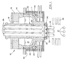
- a feeder 10 for a triple gob I.S. machine is shown in figure 1.
- the feeder 10 comprises a spout bowl 11 conventionally made from a ceramic material which contains molten glass 12 supplied from a forehearth (not shown).
- the contained molten glass can be heated by conventional gas burners (not shown) located in a burner block 14.
- a spout cover 16 On top of the burner block is a spout cover 16 which has an opening 18 through which a cylindrical tube 20 extends to define, between the bottom 22 of the tube and a flat bottom surface 24 of the spout bowl, an annular discharge path for the molten glass.
- plungers 26 Extending down through the tube 20 are three plungers 26 which project downwardly into a vertical discharge passage 30 of an elongated vertical extending neck portion 32 in alignment with corresponding orifices 34 in an orifice plate 36 which closes the passage 30.
- the plungers 26 reciprocate vertically each time gobs 37 are formed and are arranged in a common plane.
- Runners 38 of molten glass continuously flow from the orifices 34 and are cut into discrete gobs by a corresponding number of shear pairs 39 (the shears are presented schematically 90° from their correct position for purposes of clarity).
- To reduce heat loss insulation 40 is located between the spout bowl 11 and a spout bowl housing 42.
- ware 50 formed in the I.S. machine is periodically weighed by a weighing device 52 and the weight is transmitted by a suitable transmitter 54 to a Gob Weight Controller which compares the transmitted weight to a gob weight set point.
- Ware weight can be controlled by controlling the wall shear stresses of the molten glass flowing down the elongated spout neck portion 32.
- the spout neck portion 32 is elongated so that a heating/cooling element H/C can extend around the spout neck from a location proximate the orifice plate.
- a heat source 56 (which may be in the form of heating coils) powered by a power transmitter WT controlled by a Power Controller WC. Operation of the Power Controller WC is controlled by the Gob Weight Controller via a settable set point SP.
- a cooling coil 60 supplied with cooling liquid or air by a blower/pump 62.
- the temperature of the coolant can be monitored by temperature indicators TI.
- the rate of cooling is defined by a speed control SC which is controlled by a BTU controller BTUC. Operation of the BTU controller is controlled by the Gob Weight Controller via a settable set point SP.
- the Gob Weight Controller When the ware weighs too much the Gob Weight Controller will increase the set point for the BTU controller BTUC which then raises the set point SP for the blower/pump 62 to increase cooling. This increases the shear stress in the glass at the wall of the spout neck portion 32, reducing the flow of molten glass and hence reducing gob weight.
- the Gob Weight Controller increases the set point to the power controller WC to increase power transmitted to the heating coils 56 by the power transmitter to heat the wall of the spout neck portion 32 to reduce the shear stress and increase gob weight.
- a single heating/cooling element H/C may surround the spout neck 26 or the heating/cooling element can have a number of portions.
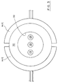
- the heating/cooling element may have a pair of semicircular elements that meet at a mid-plane transverse to the plane of the plungers and intersecting the central plunger. In that case, as shown in figure 3, each side would be controlled by evaluating the weight of ware formed from the adjacent orifice. Since this heating/cooling is only sufficient to change shear stresses, it will have little effect on the temperature of the formed gobs.
- the vertical dimension of the spout neck is chosen to provide enough annular surface area for the H/C elements to effect the desired changes to the wall shear stress of the molten glass flowing along the interior wall of the spout neck.
Landscapes
- Chemical & Material Sciences (AREA)
- Engineering & Computer Science (AREA)
- Materials Engineering (AREA)
- Organic Chemistry (AREA)
- Re-Forming, After-Treatment, Cutting And Transporting Of Glass Products (AREA)
Applications Claiming Priority (2)
| Application Number | Priority Date | Filing Date | Title |
|---|---|---|---|
| US99271492A | 1992-12-18 | 1992-12-18 | |
| US992714 | 1992-12-18 |
Publications (2)
| Publication Number | Publication Date |
|---|---|
| EP0603009A2 true EP0603009A2 (de) | 1994-06-22 |
| EP0603009A3 EP0603009A3 (de) | 1995-06-07 |
Family
ID=25538652
Family Applications (1)
| Application Number | Title | Priority Date | Filing Date |
|---|---|---|---|
| EP93310264A Withdrawn EP0603009A3 (de) | 1992-12-18 | 1993-12-17 | Speiser. |
Country Status (2)
| Country | Link |
|---|---|
| EP (1) | EP0603009A3 (de) |
| JP (1) | JPH06227824A (de) |
Cited By (3)
| Publication number | Priority date | Publication date | Assignee | Title |
|---|---|---|---|---|
| GB2306468A (en) * | 1995-11-02 | 1997-05-07 | Emhart Glass Mach Invest | Glass Feeder Heat Baffle |
| KR100355550B1 (ko) * | 1998-12-09 | 2003-01-29 | 한국전기초자 주식회사 | 유리용융로 |
| CN112358166A (zh) * | 2020-12-11 | 2021-02-12 | 重庆鑫景特种玻璃有限公司 | 一种用于玻璃窑炉卸料量调控的自动控制系统 |
Families Citing this family (1)
| Publication number | Priority date | Publication date | Assignee | Title |
|---|---|---|---|---|
| FR3094978B1 (fr) * | 2019-04-11 | 2021-04-23 | Soc Europeenne Des Produits Refractaires | Ensemble cuvette d’avant-corps d’un canal de distribution de verre |
Family Cites Families (2)
| Publication number | Priority date | Publication date | Assignee | Title |
|---|---|---|---|---|
| GB505440A (en) * | 1937-11-09 | 1939-05-09 | John Thomas Wood | Improvements in or relating to glass feeding devices |
| US2951316A (en) * | 1956-11-05 | 1960-09-06 | Owens Corning Fiberglass Corp | Process for molding massive bodies of glass having high strength |
-
1993
- 1993-12-17 JP JP31808493A patent/JPH06227824A/ja active Pending
- 1993-12-17 EP EP93310264A patent/EP0603009A3/de not_active Withdrawn
Cited By (6)
| Publication number | Priority date | Publication date | Assignee | Title |
|---|---|---|---|---|
| GB2306468A (en) * | 1995-11-02 | 1997-05-07 | Emhart Glass Mach Invest | Glass Feeder Heat Baffle |
| GB2306468B (en) * | 1995-11-02 | 1999-05-26 | Emhart Glass Mach Invest | Glass feeder heat baffle |
| KR100355550B1 (ko) * | 1998-12-09 | 2003-01-29 | 한국전기초자 주식회사 | 유리용융로 |
| CN112358166A (zh) * | 2020-12-11 | 2021-02-12 | 重庆鑫景特种玻璃有限公司 | 一种用于玻璃窑炉卸料量调控的自动控制系统 |
| WO2022121576A1 (zh) * | 2020-12-11 | 2022-06-16 | 重庆鑫景特种玻璃有限公司 | 一种用于玻璃窑炉卸料量调控的自动控制系统 |
| CN112358166B (zh) * | 2020-12-11 | 2023-11-21 | 重庆鑫景特种玻璃有限公司 | 一种用于玻璃窑炉卸料量调控的自动控制系统 |
Also Published As
| Publication number | Publication date |
|---|---|
| EP0603009A3 (de) | 1995-06-07 |
| JPH06227824A (ja) | 1994-08-16 |
Similar Documents
| Publication | Publication Date | Title |
|---|---|---|
| US4740401A (en) | Forming laminated glass containers from a composite encapsulated gob of molten glass | |
| EP0120050B1 (de) | Behandlungsmittel zur beeinflussung der temperatur geschmolzener massen | |
| CN101045602B (zh) | 玻璃成形品制造装置及玻璃成形品的制造方法 | |
| US4389725A (en) | Electric boosting control for a glass forehearth | |
| US3547611A (en) | Control system for glass melting furnaces | |
| US4305747A (en) | Multiple gob glass feeder system and method of operation | |
| US3401536A (en) | Apparatus for melting and processing heat-softenable mineral materials | |
| US3556753A (en) | Method for melting and processing heat-softenable mineral materials | |
| US2482071A (en) | Method for producing fibers | |
| EP0603009A2 (de) | Speiser | |
| CN110357399B (zh) | 用于生产玻璃产品的方法及适于此的装置 | |
| EP4482800B1 (de) | Speiserverfahren für posten und zugehöriges system | |
| US3508904A (en) | Glass feeding orifice with multichamber combustion zones | |
| US3321288A (en) | Method for controlling the temperature of heat-softenable material | |
| US2687599A (en) | Apparatus for melting glass | |
| US2226498A (en) | Glass melting and delivering apparatus and method | |
| JP4143188B2 (ja) | 色筋入りガラス製品の製造方法 | |
| US1626705A (en) | Glass feeder | |
| KR20020046075A (ko) | 유리 용융로 | |
| US2910806A (en) | Apparatus for feeding and conveying molten glass | |
| US3537277A (en) | Device for feeding glass to processing machines | |
| US1458834A (en) | Apparatus for producing charges of molten glass | |
| US2941335A (en) | Furnace for glass feeding and conditioning | |
| US6802189B2 (en) | Device and process for the remelting of glass | |
| US1750966A (en) | Automatic temperature control for glass |
Legal Events
| Date | Code | Title | Description |
|---|---|---|---|
| PUAI | Public reference made under article 153(3) epc to a published international application that has entered the european phase |
Free format text: ORIGINAL CODE: 0009012 |
|
| AK | Designated contracting states |
Kind code of ref document: A2 Designated state(s): DE FR GB IT |
|
| PUAL | Search report despatched |
Free format text: ORIGINAL CODE: 0009013 |
|
| AK | Designated contracting states |
Kind code of ref document: A3 Designated state(s): DE FR GB IT |
|
| STAA | Information on the status of an ep patent application or granted ep patent |
Free format text: STATUS: THE APPLICATION IS DEEMED TO BE WITHDRAWN |
|
| 18D | Application deemed to be withdrawn |
Effective date: 19951208 |