EP0603035A1 - Procédé de plastification de documents découpés dans une feuille - Google Patents
Procédé de plastification de documents découpés dans une feuille Download PDFInfo
- Publication number
- EP0603035A1 EP0603035A1 EP19930402984 EP93402984A EP0603035A1 EP 0603035 A1 EP0603035 A1 EP 0603035A1 EP 19930402984 EP19930402984 EP 19930402984 EP 93402984 A EP93402984 A EP 93402984A EP 0603035 A1 EP0603035 A1 EP 0603035A1
- Authority
- EP
- European Patent Office
- Prior art keywords
- document
- cover
- marks
- cutting
- plastic
- Prior art date
- Legal status (The legal status is an assumption and is not a legal conclusion. Google has not performed a legal analysis and makes no representation as to the accuracy of the status listed.)
- Granted
Links
- 238000000034 method Methods 0.000 title claims abstract description 23
- 238000010030 laminating Methods 0.000 title claims abstract description 6
- 239000000463 material Substances 0.000 title description 3
- 238000005520 cutting process Methods 0.000 claims abstract description 59
- 229920003023 plastic Polymers 0.000 claims abstract description 41
- 239000004033 plastic Substances 0.000 claims abstract description 41
- 239000011159 matrix material Substances 0.000 claims description 17
- 230000000149 penetrating effect Effects 0.000 claims 1
- 238000003475 lamination Methods 0.000 abstract 1
- 238000010438 heat treatment Methods 0.000 description 3
- 238000004519 manufacturing process Methods 0.000 description 3
- 239000004698 Polyethylene Substances 0.000 description 1
- 238000000151 deposition Methods 0.000 description 1
- 229920000728 polyester Polymers 0.000 description 1
- -1 polyethylene Polymers 0.000 description 1
- 229920000573 polyethylene Polymers 0.000 description 1
- 238000007789 sealing Methods 0.000 description 1
Images


Classifications
-
- B—PERFORMING OPERATIONS; TRANSPORTING
- B32—LAYERED PRODUCTS
- B32B—LAYERED PRODUCTS, i.e. PRODUCTS BUILT-UP OF STRATA OF FLAT OR NON-FLAT, e.g. CELLULAR OR HONEYCOMB, FORM
- B32B37/00—Methods or apparatus for laminating, e.g. by curing or by ultrasonic bonding
- B32B37/14—Methods or apparatus for laminating, e.g. by curing or by ultrasonic bonding characterised by the properties of the layers
- B32B37/16—Methods or apparatus for laminating, e.g. by curing or by ultrasonic bonding characterised by the properties of the layers with all layers existing as coherent layers before laminating
- B32B37/22—Methods or apparatus for laminating, e.g. by curing or by ultrasonic bonding characterised by the properties of the layers with all layers existing as coherent layers before laminating involving the assembly of both discrete and continuous layers
-
- B—PERFORMING OPERATIONS; TRANSPORTING
- B32—LAYERED PRODUCTS
- B32B—LAYERED PRODUCTS, i.e. PRODUCTS BUILT-UP OF STRATA OF FLAT OR NON-FLAT, e.g. CELLULAR OR HONEYCOMB, FORM
- B32B38/00—Ancillary operations in connection with laminating processes
- B32B38/18—Handling of layers or the laminate
- B32B38/1825—Handling of layers or the laminate characterised by the control or constructional features of devices for tensioning, stretching or registration
- B32B38/1833—Positioning, e.g. registration or centering
-
- B—PERFORMING OPERATIONS; TRANSPORTING
- B32—LAYERED PRODUCTS
- B32B—LAYERED PRODUCTS, i.e. PRODUCTS BUILT-UP OF STRATA OF FLAT OR NON-FLAT, e.g. CELLULAR OR HONEYCOMB, FORM
- B32B2425/00—Cards, e.g. identity cards, credit cards
-
- Y—GENERAL TAGGING OF NEW TECHNOLOGICAL DEVELOPMENTS; GENERAL TAGGING OF CROSS-SECTIONAL TECHNOLOGIES SPANNING OVER SEVERAL SECTIONS OF THE IPC; TECHNICAL SUBJECTS COVERED BY FORMER USPC CROSS-REFERENCE ART COLLECTIONS [XRACs] AND DIGESTS
- Y10—TECHNICAL SUBJECTS COVERED BY FORMER USPC
- Y10T—TECHNICAL SUBJECTS COVERED BY FORMER US CLASSIFICATION
- Y10T156/00—Adhesive bonding and miscellaneous chemical manufacture
- Y10T156/10—Methods of surface bonding and/or assembly therefor
- Y10T156/1052—Methods of surface bonding and/or assembly therefor with cutting, punching, tearing or severing
- Y10T156/1056—Perforating lamina
-
- Y—GENERAL TAGGING OF NEW TECHNOLOGICAL DEVELOPMENTS; GENERAL TAGGING OF CROSS-SECTIONAL TECHNOLOGIES SPANNING OVER SEVERAL SECTIONS OF THE IPC; TECHNICAL SUBJECTS COVERED BY FORMER USPC CROSS-REFERENCE ART COLLECTIONS [XRACs] AND DIGESTS
- Y10—TECHNICAL SUBJECTS COVERED BY FORMER USPC
- Y10T—TECHNICAL SUBJECTS COVERED BY FORMER US CLASSIFICATION
- Y10T156/00—Adhesive bonding and miscellaneous chemical manufacture
- Y10T156/10—Methods of surface bonding and/or assembly therefor
- Y10T156/1052—Methods of surface bonding and/or assembly therefor with cutting, punching, tearing or severing
- Y10T156/1062—Prior to assembly
- Y10T156/107—Punching and bonding pressure application by punch
-
- Y—GENERAL TAGGING OF NEW TECHNOLOGICAL DEVELOPMENTS; GENERAL TAGGING OF CROSS-SECTIONAL TECHNOLOGIES SPANNING OVER SEVERAL SECTIONS OF THE IPC; TECHNICAL SUBJECTS COVERED BY FORMER USPC CROSS-REFERENCE ART COLLECTIONS [XRACs] AND DIGESTS
- Y10—TECHNICAL SUBJECTS COVERED BY FORMER USPC
- Y10T—TECHNICAL SUBJECTS COVERED BY FORMER US CLASSIFICATION
- Y10T156/00—Adhesive bonding and miscellaneous chemical manufacture
- Y10T156/10—Methods of surface bonding and/or assembly therefor
- Y10T156/1052—Methods of surface bonding and/or assembly therefor with cutting, punching, tearing or severing
- Y10T156/1062—Prior to assembly
- Y10T156/1075—Prior to assembly of plural laminae from single stock and assembling to each other or to additional lamina
- Y10T156/1077—Applying plural cut laminae to single face of additional lamina
-
- Y—GENERAL TAGGING OF NEW TECHNOLOGICAL DEVELOPMENTS; GENERAL TAGGING OF CROSS-SECTIONAL TECHNOLOGIES SPANNING OVER SEVERAL SECTIONS OF THE IPC; TECHNICAL SUBJECTS COVERED BY FORMER USPC CROSS-REFERENCE ART COLLECTIONS [XRACs] AND DIGESTS
- Y10—TECHNICAL SUBJECTS COVERED BY FORMER USPC
- Y10T—TECHNICAL SUBJECTS COVERED BY FORMER US CLASSIFICATION
- Y10T156/00—Adhesive bonding and miscellaneous chemical manufacture
- Y10T156/10—Methods of surface bonding and/or assembly therefor
- Y10T156/1052—Methods of surface bonding and/or assembly therefor with cutting, punching, tearing or severing
- Y10T156/1084—Methods of surface bonding and/or assembly therefor with cutting, punching, tearing or severing of continuous or running length bonded web
-
- Y—GENERAL TAGGING OF NEW TECHNOLOGICAL DEVELOPMENTS; GENERAL TAGGING OF CROSS-SECTIONAL TECHNOLOGIES SPANNING OVER SEVERAL SECTIONS OF THE IPC; TECHNICAL SUBJECTS COVERED BY FORMER USPC CROSS-REFERENCE ART COLLECTIONS [XRACs] AND DIGESTS
- Y10—TECHNICAL SUBJECTS COVERED BY FORMER USPC
- Y10T—TECHNICAL SUBJECTS COVERED BY FORMER US CLASSIFICATION
- Y10T156/00—Adhesive bonding and miscellaneous chemical manufacture
- Y10T156/10—Methods of surface bonding and/or assembly therefor
- Y10T156/1089—Methods of surface bonding and/or assembly therefor of discrete laminae to single face of additional lamina
- Y10T156/1092—All laminae planar and face to face
- Y10T156/1093—All laminae planar and face to face with covering of discrete laminae with additional lamina
- Y10T156/1095—Opposed laminae are running length webs
-
- Y—GENERAL TAGGING OF NEW TECHNOLOGICAL DEVELOPMENTS; GENERAL TAGGING OF CROSS-SECTIONAL TECHNOLOGIES SPANNING OVER SEVERAL SECTIONS OF THE IPC; TECHNICAL SUBJECTS COVERED BY FORMER USPC CROSS-REFERENCE ART COLLECTIONS [XRACs] AND DIGESTS
- Y10—TECHNICAL SUBJECTS COVERED BY FORMER USPC
- Y10T—TECHNICAL SUBJECTS COVERED BY FORMER US CLASSIFICATION
- Y10T83/00—Cutting
- Y10T83/04—Processes
- Y10T83/0495—Making and using a registration cut
-
- Y—GENERAL TAGGING OF NEW TECHNOLOGICAL DEVELOPMENTS; GENERAL TAGGING OF CROSS-SECTIONAL TECHNOLOGIES SPANNING OVER SEVERAL SECTIONS OF THE IPC; TECHNICAL SUBJECTS COVERED BY FORMER USPC CROSS-REFERENCE ART COLLECTIONS [XRACs] AND DIGESTS
- Y10—TECHNICAL SUBJECTS COVERED BY FORMER USPC
- Y10T—TECHNICAL SUBJECTS COVERED BY FORMER US CLASSIFICATION
- Y10T83/00—Cutting
- Y10T83/04—Processes
- Y10T83/0524—Plural cutting steps
- Y10T83/0577—Repetitive blanking
Definitions
- the present invention relates to a method of laminating documents cut from a sheet. It applies in particular to the laminating of original documents such as identity cards or any other identification documents for example. More generally, it applies to the laminating of documents printed on a sheet and the state of which it is necessary to save for reasons of security or reliability.
- the quality of plasticization of identification documents contributes in particular to the security and reliability that these must provide. Different criteria help define this quality. Among these, the regularity of the plastic edges plays an important role. It is indeed important that the document, an identification card of rectangular shape for example, is well centered in the middle of the plastic rectangle covering it for reasons of automatic recognition or reliability of the document for example.
- plasticization methods which make it possible to obtain the latter quality criterion.
- these methods are implemented by means of complex and expensive machines, adapted in particular to centralized productions processing large quantities of documents.
- These machines make use in particular of automatic means for locating the position of the cards relative to the plastic strips covering them, this marking being for example carried out with respect to the edges of the document to be laminated and means for cutting plastic covering strips. .
- Another known means consists of manually positioning the documents and visually checking their positioning. In addition to the risks of positioning errors inherent in this type of human activity, such a process is incompatible with production greater than a few units.
- the object of the invention is to overcome the aforementioned drawbacks, in particular by making it possible to obtain regular plastic edges in a simple and reliable manner.
- the main advantages of the invention are that it is suitable for all types of production of plasticized documents, in particular semi-industrial documents, that it is simple to implement and that it is economical.
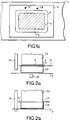
- FIGS 1a, 1b and 1c illustrate the principle of the method according to the invention.
- FIG. 1a shows a document 5, fixed on a first plastic cover 3, a strip of plastic for example. At least two marks 1, 2, for example punctual, are produced on the first cover 3.
- the positions of the first marks 1, 2 are defined beforehand with respect to a first cutting line 4 which is the cutting line of the document 5 to laminate, this document being previously cut from a sheet.
- the document is attached to the first cover 3, preferably inside the cutting line 4. This can be obtained for example by placing the first cover 3 just at the exit of a matrix of cutting the document 5. It is not compulsory for the document 5 to remain inside its cutting line 4, however its position on the first cover 3 must be defined relative to the cutting line 4.
- a second plastic cover is fixed to the back of the document 5.
- the second cover is fixed after the first marks have been made, it is placed so as not to hide them. If the second cover is fixed before the first marks are made, these can for example be made on the two covers at the same time.
- the fixing of the covers on the document can for example be carried out by heating points.
- Figure 1b shows a second cutting line 6 which is the cutting line for the assembly formed by the document and its two plastic covers.
- This second cutting line 6 is not, for example, constituted by the edges of a die or of a cutting punch.
- the position of the second cutting line 6 is fixed and defined with respect to at least two second marks 7, 8 for example located on a cutting module 9 comprising the second cutting line 6. These two marks 7, 8 are for example punctual.
- the relative positions of the second marks 7, 8 are identical to the relative positions of the first marks 1, 2.
- FIG. 1c shows the superposition of the cutting module 9 and of the entire document 5 and of its plastic covers, only one of which is shown.
- the second cutting line 6 of the assembly 3, 5 frames the first cutting line 4 of the document.
- the entire document and its covers are cut only when there is agreement between the first marks 1, 2 and the second marks 7, 8, the positions of the first marks 1, 2 relative to the first cutting line 4 and the position of the second cutting line 6 relative to the positions of the second marks 7, 8 having been defined so to get this regularity.
- these positions could previously be defined so as to obtain a different placement of the document with respect to its plastic protection, so as for example to obtain plastic edges of different widths from one side to the other.
- the first one cutting line 4 can for example be inside the second cutting line 6 as illustrated in FIG. 1c.
- the second cutting line 6 can also for example be inside the first cutting line 4, in this case the document is cut again.
- the positions of the first marks on the first plastic cover can be arbitrary with respect to the first cutting line 4, the document cutting line 5, provided that these positions are fixed and defined with respect to this first cutting line 4.
- the first marks can for example be inside the latter, therefore inside the document 5 for example.
- the first 1, 2 and second 7, 8 marks may for example be holes or marking points.
- FIG. 2a presents a sheet 21 placed between a first punch 22 for cutting and its associated matrix 23.
- the cutting of the document 5 contained on the sheet 21 is obtained by the passage of the first punch 22 through its matrix 23, the document 5 being placed between these last two.
- To the first punch 22 is coupled two auxiliary punches of which only one 24 is shown, the other being hidden by the latter.
- the positions of the auxiliary punches 24 and of the first punch 22 are fixed to one another in a plane perpendicular to their common direction of movement.
- the first plastic cover 3 to be fixed to the front of the document 5 is for example placed just below, in contact, the matrix 23 so that at the output of the latter, the document 5 pushed by the first punch 22 , or placed directly on this first cover 3. This allows in particular to keep the position of the document 5 inside its cutting line 4 formed by the opposite edges of the first punch 22 and its matrix 23.
- a heating element 25 located near and below it allows for example to fix it on the document by a heating point, the total plasticization of the front of the document that can for example be produced later.
- the first cover 3 is for example a plastic strip whose adhesion face, facing the document to be laminated, is for example made of polyethylene, and whose external face is for example made of polyester, the temperature of the latter material does not not being sensitive to the sealing temperature of the adhesion face.
- the cover can be made of any other plastic material which can be heat-sealed, for example by means of systems known to those skilled in the art.
- the first cover 3 consists of a plastic strip running under the matrix 23, the strip cannot be located just below, in contact with the matrix 23 for reasons of friction in particular. A space being provided between the matrix and the strip, it is then possible to provide a system lifting this strip at the time of the output of a document from the matrix 23, the strip then being in contact with the latter at the time of removal. of the document.
- the auxiliary punches 24 move in the same direction as the first punch 22 so as to pierce two holes in the first cover 3 like the illustrates FIG. 2b, these holes acting as first marks 1, 2 above.
- FIG. 2c illustrates an example of positioning a second plastic cover 3 on the back of the document 5, the holes 1, 2 having been made on the first cover 3 and the latter being fixed to the front of the document 5.
- the second cover 3 ' is for example fixed on the document 5 so as not to cover the holes 1, 2 and to completely cover the document.
- FIG. 2d illustrates the positioning of the assembly consisting of the document 5 and its two covers 3, 3 'just before the cutting of this assembly by a second punch 26 and its associated matrix 27.
- the assembly 5, 3, 3' is positioned so that the holes 1, 2 previously made are engaged around studs are only one 7, 8 is shown, the other being hidden by the latter.
- These studs have a diameter substantially equal to that of the holes. They are fixed relative to the projection of the cutting line 6 of the assembly in a plane perpendicular to the direction of movement of the second punch 26, this cutting line 6 being defined by the opposite edges of the second punch 26 and its matrix 27.
- the two pads 7, 8 are for example mechanically integral with this matrix 27. These two pads act as second pins 7, 8 above.
- the entire document 5 and its covers 3, 3 ′ can be cut out.
- the holes 1, 2 and the studs 7, 8 having identical relative positions between them, the positions of the holes 1, 2 therefore of the auxiliary punches 24 relative to the first punch 22 and the positions of the studs 7, 8 relative to the second punch 26 or its associated matrix 27 are such that they allow for example the obtaining of regular plastic edges around the document 5.
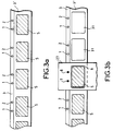
- FIGS. 3a and 3b illustrate a case of application of the method according to the invention in which the documents to be laminated 5 are fixed thereafter, after cutting, on a first plastic strip 3 as shown in FIG. 3a, the strip passing by example under a cutting system of the type of that of FIG. 2a. Holes 1, 2 are made simultaneously with the fixing of the front of each document 5 on the strip. A second plastic strip 3 'is fixed to the back of the documents 5 by covering them without covering the holes 1, 2. The latter are for example produced in accordance with the aforementioned method relating to FIGS. 2a and 2b.
- Figure 3b shows the cutting of plasticized documents, that is to say documents 5 and plastic strips 3, 3 'as shown in Figure 3a.
- the cutting die 27 associated with the second punch 26 is shown above the strips 3, 3 ', a document 5 being ready to be cut with the plastic strips 3, 3'.
- the pads 7, 8 mechanically integral with the die 27 are engaged in the holes associated with the document to be cut so that, for example, this document 5 is well centered in the middle of the cutting line 6. After passing through the die 27, holes 31 appear in the strips 3, 3 ′ corresponding to the location of the cut plastic documents.
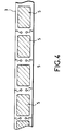
- FIG. 4 shows another possible position of the holes 1, 2 on the first plastic strip 3.
- the latter are for example produced between the documents 5.
- the second plastic strip 3 ′ has for example holes of dimensions superior to previous 1, 2 so that this second strip does not cover these holes 1, 2 made in the first strip 3.
- the holes 1, 2 can also be placed differently on the first plastic strip 3. They can in particular be placed inside the document 5 if space saving is necessary on the strip, for the purpose of economy for example.
- the method according to the invention is applicable for example if a document is laminated on one side, a second plastic cover is not then attached to the back of the document.
- the plastic cover and the document can for example be cut so that they are edge to edge.
- the aforementioned point marks 1, 2, 7, 8 may for example be included in marks which are not reduced to points such as holes or circular punches in particular.
- the marks 7, 8 can be included in a punch of rectangular section and the corresponding marks 1, 2 can be included in a rectangular hole matching the shape of the punch with rectangular section.
- the marks 1, 2 made in the first plastic cover 3 and the marks 7, 8 linked to the second cutting line 6 can therefore be for example respectively included in a single mark made on the first cover 3 and a single mark linked to the second cutting line 6, the cutting of the plastic document taking place when there is agreement between these two marks only.
Landscapes
- Lining Or Joining Of Plastics Or The Like (AREA)
- Perforating, Stamping-Out Or Severing By Means Other Than Cutting (AREA)
- Laminated Bodies (AREA)
- Collation Of Sheets And Webs (AREA)
Abstract
Description
- La présente invention concerne un procédé de plastification de documents découpés dans une feuille. Elle s'applique notamment à la plastification de documents originaux tels que des cartes d'identité ou tout autres documents d'identification par exemple. Plus généralement, elle s'applique à la plastification de documents imprimés sur une feuille et dont il est nécessaire de sauvegarder l'état pour des raisons de sécurité ou de fiabilité.
- La qualité de plastification de documents d'identification participe notamment à la sécurité et à la fiabilité que doivent procurer ces derniers. Différents critères concourent à définir cette qualité. Parmi ceux-ci, la régularité des bords de plastique joue un rôle important. Il importe en effet que le document, une carte d'identification de forme rectangulaire par exemple, soit bien centré au milieu du rectangle de plastique la recouvrant pour des raisons de reconnaissance automatique ou de fiabilité du document par exemple.
- Il existe des procédés connus de plastification permettant d'obtenir ce dernier critère de qualité. Cependant ces procédés sont mis en oeuvre au moyen de machines complexes et coûteuses, adaptées notamment à des productions centralisées traitant de grandes quantités de documents. Ces machines font notamment appel à des moyens automatiques de repérage de la position des cartes par rapport aux bandes de plastiques les recouvrant, ce repérage étant par exemple effectué par rapport aux bords du document à plastifier et des moyens de découpe de bandes de recouvrement en plastique.
- Un autre moyen connu consiste à positionner manuellement les documents et à vérifier visuellement leur positionnement. Outre les risques d'erreurs de positionnement inhérents à ce type d'activité humaine, un tel procédé est incompatible d'une production supérieure à quelques unités.
- Le but de l'invention est de palier les inconvénients précités, notamment en permettant d'obtenir de façon simple et fiable des bords de plastique réguliers.
- A cet effet, l'invention a pour objet un procédé de plastification d'un document découpé dans une feuille par des moyens de découpe selon une première ligne de découpe (4), caractérisé en ce que :
- dans une première étape, au moins une couverture en plastique étant fixée sur le document, au moins deux premiers repères sont réalisés sur la couverture, les positions des premiers repères étant préalablement définies par rapport à la ligne de découpe du document dont la position sur la couverture est définie par rapport à cette ligne de découpe ;
- dans une deuxième étape, la position de la ligne de découpe de l'ensemble du document et de la couverture étant préalablement définie par rapport à au moins deux seconds repères, la découpe de l'ensemble est réalisée quand il y a concordance entre les premiers et les seconds repères.
- L'invention a pour principaux avantages qu'elle est adaptée à tous types de production de documents plastifiés, notamment semi-industriels, qu'elle est simple à mettre en oeuvre et qu'elle est économique.
- D'autres caractéristiques et avantages de l'invention apparaîtront à l'aide de la description qui suit faite en regard des dessins annexés qui représentent :
- les figures 1a, 1b, 1c, des illustrations du principe du procédé selon l'invention ;
- les figures 2a, 2b, 2c et 2d, une illustration d'un exemple de mise en oeuvre possible du procédé selon l'invention;
- les figures 3a, 3b et 4, une application comprenant plusieurs documents à plastifier.
- Les figures 1a, 1b et 1c illustrent le principe du procédé selon l'invention.
- La figure 1a montre un document 5, fixé sur une première couverture en plastique 3, une bande de plastique par exemple. Au moins deux repères 1, 2, par exemple ponctuels, sont réalisés sur la première couverture 3. Les positions des premiers repères 1, 2 sont préalablement définis par rapport à une première ligne de découpe 4 qui est la ligne de découpe du document 5 à plastifier, ce document étant préalablement découpé dans une feuille. Le document est fixé à la première couverture 3, de préférence à l'intérieur de la ligne de découpe 4. Cela peut être obtenu par exemple en plaçant la première couverture 3 juste en sortie d'une matrice de découpe du document 5. Il n'est pas obligatoire que le document 5 reste à l'intérieur de sa ligne de découpe 4, cependant il faut que sa position sur la première couverture 3 soit définie par rapport à la ligne de découpe 4. Avant ou après la réalisation des premiers repères 1, 2 sur la première couverture 3, une deuxième couverture en plastique, non représentée, est fixée au verso du document 5. Si la deuxième couverture est fixée après la réalisation des premiers repères, elle est placée de façon à ne pas les cacher. Si la deuxième couverture est fixée avant la réalisation des premiers repères, ceux-ci peuvent par exemple être réalisés sur les deux couvertures à la fois. La fixation des couvertures sur le document peut par exemple être réalisée par des points de chauffage.
- La figure 1b montre une deuxième ligne de découpe 6 qui est la ligne de découpe de l'ensemble constitué par le document et ses deux couvertures en plastique. Cette deuxième ligne de découpe 6 est pas exemple constitué par les bords d'une matrice ou d'un poinçon de découpe. La position de la deuxième ligne de découpe 6 est fixe et définie par rapport à au moins deux seconds repères 7, 8 par exemple situés sur un module de découpe 9 comprenant la deuxième ligne de découpe 6. Ces deux repères 7, 8 sont par exemple ponctuels. Les positions relatives des seconds repères 7, 8 sont identiques aux positions relatives des premiers repères 1, 2.
- La figure 1c présente la superposition du module de découpe 9 et de l'ensemble du document 5 et de ses couvertures en plastique dont une seule 3 est représentée. La deuxième ligne de découpe 6 de l'ensemble 3, 5 encadre la première ligne de découpe 4 du document. Selon l'invention, afin d'obtenir des bords de plastique réguliers autour de document 5 plastifié, la découpe de l'ensemble du document et de ses couvertures n'est effectué que lorsqu'il y a concordance entre les premiers repères 1, 2 et les seconds repères 7, 8, les positions des premiers repères 1, 2 par rapport à la première ligne de découpe 4 et la position de la deuxième ligne de découpe 6 par rapport aux positions des seconds repères 7, 8 ayant été définis de façon à obtenir cette régularité. Cependant, ces positions pourraient préalablement être définies de façon à obtenir un placement différent du document par rapport à sa protection en plastique, de façon par exemple à obtenir des bords en plastique de largeurs différentes d'un côté à l'autre. La première ligne de découpe 4 peut être par exemple à l'intérieur de la deuxième ligne de découpe 6 comme l'illustre la figure 1c.
- Toutefois les deux lignes de découpe peuvent être confondues si des bords en plastique ne sont pas souhaités. La deuxième ligne de découpe 6 peut aussi par exemple être à l'intérieur de la première ligne de découpe 4, dans ce cas le document est découpé une nouvelle fois. Dès lors où les positions relatives des premiers repères entre eux et des seconds repères entre eux sont identiques, les positions des premiers repères sur la première couverture en plastique peuvent être quelconques par rapport à la première ligne de découpe 4, la ligne de découpe du document 5, à condition que ces positions soient fixes et définies par rapport à cette première ligne de découpe 4. Les premiers repères peuvent par exemple être à l'intérieur de cette dernière, donc à l'intérieur du document 5 par exemple. Les premiers 1, 2 et seconds 7, 8 repères peuvent être par exemple des trous ou des points de marquage.
- Les figures 2a à 2d illustrent un exemple de mise en oeuvre possible du procédé selon l'invention. La figure 2a présente une feuille 21 placée entre un premier poinçon 22 de découpe et sa matrice associée 23. La découpe du document 5 contenu sur la feuille 21 est obtenu par le passage du premier poinçon 22 à travers sa matrice 23, le document 5 étant placé entre ces deux derniers. Au premier poinçon 22 est couplé deux poinçons auxiliaires dont un seul 24 est représenté, l'autre étant caché par ce dernier.
- Les positions des poinçons auxiliaires 24 et du premier poinçon 22 sont fixes entre elles dans un plan perpendiculaire à leur commune direction de déplacement. La première couverture de plastique 3 devant être fixée au recto du document 5 est par exemple placée juste en dessous, au contact, de la matrice 23 de façon à ce qu'en sortie de cette dernière, le document 5 poussé par le premier poinçon 22, soit posé directement sur cette première couverture 3. Cela permet notamment de bien conserver la position du document 5 à l'intérieur de sa ligne de découpe 4 constituée par les bords en vis à vis du premier poinçon 22 et de sa matrice 23. A l'instant de la dépose du document 5 sur la première couverture 3, un élément chauffant 25 situé à proximité et en dessous de celle-ci permet par exemple de la fixer sur le document par un point de chauffage, la plastification totale du recto du document pouvant par exemple être réalisée ultérieurement.
- La première couverture 3 est par exemple une bande de plastique dont la face d'adhérence, tournée vers le document à plastifier, est par exemple en polyéthylène, et dont la face extérieure est par exemple en polyester, la température de ce dernier matériau n'étant pas sensible à la température de scellage de la face d'adhérence. La couverture peut être en tout autre matériau en plastique scellable à chaud par exemple au moyen de systèmes connus de l'homme du métier. Dans le cas où la première couverture 3 est constituée d'une bande en plastique défilant sous la matrice 23, la bande ne peut pas être située juste en dessous, au contact de la matrice 23 pour des raisons de frottement notamment. Un espacement étant ménagé entre la matrice et la bande, il est alors possible de prévoir un système soulevant cette bande au moment de la sortie d'un document de la matrice 23, la bande étant alors au contact de cette dernière au moment de la dépose du document.
- Simultanément au passage du premier poinçon 22 dans sa matrice 23, donc simultanément à la découpe du document 5, les poinçons auxiliaires 24 se déplacent dans le même sens que le premier poinçon 22 de façon à percer deux trous dans la première couverture 3 comme l'illustre la figure 2b, ces trous faisant offices de premiers repères 1, 2 précités.
- La figure 2c illustre un exemple de positionnement d'une deuxième couverture de plastique 3 au verso du document 5, les trous 1, 2 ayant été réalisés sur la première couverture 3 et celle-ci étant fixée au recto du document 5. La deuxième couverture 3' est par exemple fixée sur le document 5 de façon à ne pas couvrir les trous 1, 2 et à couvrir entièrement le document.
- La figure 2d illustre le positionnement de l'ensemble constitué du document 5 et de ses deux couvertures 3, 3' juste avant la découpe de cet ensemble par un deuxième poinçon 26 et sa matrice associée 27. L'ensemble 5, 3, 3' est positionné de façon à ce que les trous 1, 2 précédemment effectués soient engagés autours de plots sont un seul 7, 8 est représenté, l'autre étant caché par ce dernier. Ces plots ont un diamètre sensiblement égal à celui des trous. lls sont fixes par rapport à la projection de la ligne de découpe 6 de l'ensemble dans un plan perpendiculaire à la direction de déplacement du deuxième poinçon 26, cette ligne de découpe 6 étant définie par les bords en vis à vis du deuxième poinçon 26 et de sa matrice 27. Les deux plots 7, 8 sont par exemple solidaires mécaniquement de cette matrice 27. Ces deux plots font office des seconds repères 7, 8 précités. Ils ont par exemple un sommet conique pour s'engager facilement dans les trous 1, 2 de la première couverture en plastique 3. Une fois la correspondance effectuée entre les trous 1, 2 et les plots 7, 8 précités par l'engagement de ces derniers dans les premiers, la découpe de l'ensemble du document 5 et de ses couvertures 3, 3' peut être réalisée. Les trous 1, 2 et les plots 7, 8 ayant des positions relatives entre eux identiques, les positions des trous 1, 2 donc des poinçons auxiliaires 24 par rapport au premier poinçon 22 et les positions des plots 7, 8 par rapport au deuxième poinçon 26 ou à sa matrice associée 27 sont telles qu'ils permettent par exemple l'obtention de bords de plastique réguliers autour du document 5.
- Les figures 3a et 3b illustrent un cas d'application du procédé selon l'invention où les documents à plastifier 5 sont fixés à la suite, après découpe, sur une première bande en plastique 3 comme le montre la figure 3a, la bande défilant par exemple sous un système de découpe du type de celui de la figure 2a. Des trous 1, 2 sont réalisés simultanément à la fixation du recto de chaque document 5 sur la bande. Une deuxième bande en plastique 3' est fixée au verso des documents 5 en recouvrant ceux-ci sans recouvrir les trous 1, 2. Ces derniers sont par exemple réalisés conformément à la méthode précitée relative aux figures 2a et 2b.
- La figure 3b présente la découpe des documents plastifiés, c'est à dire des documents 5 et des bandes en plastique 3, 3' tels que présentés par la figure 3a. La matrice de découpe 27 associée au deuxième poinçon 26 est représentée au-dessus des bandes 3, 3', un document 5 étant prêt à être découpé avec les bandes en plastique 3, 3'. Les plots 7, 8 solidaires mécaniquement de la matrice 27 sont engagés dans les trous associés au document à découper de façon par exemple à ce que ce document 5 soit bien centré au milieu de la ligne de découpe 6. Après passage au niveau de la matrice 27, des trous 31 apparaissent dans les bandes 3, 3' correspondant à l'emplacement des documents plastifiés découpés.
- La figure 4 présente une autre position possible des trous 1, 2 sur la première bande en plastique 3. Ces derniers sont par exemple réalisés entre les documents 5. Dans ce cas, la deuxième bande en plastique 3' possède par exemple des trous de dimensions supérieures aux précédents 1, 2 de façon à ce que cette deuxième bande ne recouvre pas ces trous 1, 2 réalisés dans la première bande 3.
- Les trous 1, 2 peuvent encore être placés différemment sur la première bande en plastique 3. Ils peuvent notamment être placés à l'intérieur du document 5 si un gain de place est nécessaire sur la bande, dans un but d'économie par exemple.
- Le procédé selon l'invention est applicable par exemple si un document est plastifié sur une seule face, une deuxième couverture en plastique n'étant pas alors fixée au verso du document. Dans ce cas, la couverture en plastique et le document peuvent par exemple être découpés de façon à ce qu'ils soient bord à bord.
- Les repères ponctuels 1, 2, 7, 8 précités peuvent par exemple être inclus dans des repères qui ne se réduisent pas à des points tels que des trous ou des poinçons circulaires notamment. A titre d'exemple les repères 7, 8 peuvent être inclus dans un poinçon de section rectangulaire et les repères correspondants 1, 2 peuvent être inclus dans un trou rectangulaire épousant la forme du poinçon à section rectangulaire. Les repères 1, 2 réalisés dans la première couverture en plastique 3 et les repères 7, 8 liés à la deuxième ligne de découpe 6 peuvent être donc par exemple respectivement inclus dans un seul repère réalisé sur la première couverture 3 et un seul repère lié à la deuxième ligne de découpe 6, la découpe du document plastiqué ayant lieu quand il y a concordance entre ces deux seuls repères. Cependant, il n'en reste pas moins que la concordance de ces derniers implique la concordance d'au moins deux repères ponctuels du repère de la couverture 3 avec au moins deux repères ponctuels du repère liés à la deuxième ligne de découpe 6, ces repères ponctuels étant bien définis, l'inclusion de deux repères ponctuels dans un seul repère étant due par exemple à des facilités de mise en oeuvre.
Claims (9)
- Procédé de plastification d'un document découpé dans une feuille (21) par des moyens de découpe selon une première ligne de découpe (4), caractérisé en ce que :- dans une première étape, au moins une couverture en plastique (3) étant fixée sur le document (5), au moins deux premiers repères (1, 2) sont réalisés sur la couverture (3), les positions des premiers repères (1, 2) étant préalablement définies par rapport à la première ligne de découpe (4) du document (5) dont la position sur la couverture (3) est définie par rapport à cette ligne de découpe (4) ;- dans une deuxième étape, la position d'une deuxième ligne de découpe (6) de l'ensemble du document (5) et de la couverture (3) étant préalablement définie par rapport à au moins deux seconds repères (7, 8), la découpe de l'ensemble (5, 3) est réalisée quand il y a concordance entre les premiers (1, 2) et les seconds (7, 8) repères.
- Procédé selon la revendication 1, caractérisé en ce qu'une deuxième couverture en plastique (3') est fixée sur la face du document (5) opposée à la première couverture (3) de façon à ne pas couvrir les premiers repères (1, 2) réalisés sur cette dernière.
- Procédé selon l'une quelconque des revendications précédentes, caractérisé en ce que les premiers repères (1, 2) sont des trous.
- Procédé selon l'une quelconque des revendications précédentes, caractérisé en ce que les seconds repères sont des plots (7, 8).
- Procédé selon la revendications 3 , caractérisé en ce que le document (5) étant préalablement situé entre un premier poinçon (22) et sa matrice associée (23), étant découpé par le passage du premier poinçon (22) à travers sa matrice (23), la couverture en plastique (3) étant au contact de la matrice (23) de façon à recevoir le document découpé en sortie de matrice, des poinçons auxiliaires (24) se déplacent vers la couverture (3) simultanément au premier poinçon de façon à réaliser les deux trous (1, 2) dans la couverture (3), la position des poinçons auxiliaires étant fixes dans un plan perpendiculaire à la direction de déplacement du premier poinçon.
- Procédé selon les revendications 3 et 4, caractérisé en ce que la découpe de l'ensemble du document (5) et de la couverture (3) est réalisée quand les trous (1, 2) sont engagés dans les plots (7, 8).
- Procédé selon la revendication 6, caractérisé en ce que la découpe de l'ensemble est réalisée par un deuxième poinçon (26) pénétrant dans sa matrice associée (27), les plots étant solidaires mécaniquement de cette matrice (27).
- Procédé selon l'une quelconque des revendications précédentes, caractérisé en ce que la couverture en plastique (3) est une bande en plastique sur laquelle sont fixées plusieurs documents (5) à la suite.
- Procédé selon les revendications 3 et 8, caractérisé en ce que les trous (1, 2) sont réalisés entre les documents.
Applications Claiming Priority (2)
| Application Number | Priority Date | Filing Date | Title |
|---|---|---|---|
| FR9215083 | 1992-12-15 | ||
| FR9215083A FR2699109B1 (fr) | 1992-12-15 | 1992-12-15 | Procédé de plastification de documents découpés dans une feuille. |
Publications (2)
| Publication Number | Publication Date |
|---|---|
| EP0603035A1 true EP0603035A1 (fr) | 1994-06-22 |
| EP0603035B1 EP0603035B1 (fr) | 1999-04-07 |
Family
ID=9436595
Family Applications (1)
| Application Number | Title | Priority Date | Filing Date |
|---|---|---|---|
| EP19930402984 Expired - Lifetime EP0603035B1 (fr) | 1992-12-15 | 1993-12-10 | Procédé de plastification de documents découpés dans une feuille |
Country Status (7)
| Country | Link |
|---|---|
| US (1) | US5474636A (fr) |
| EP (1) | EP0603035B1 (fr) |
| JP (1) | JPH06210731A (fr) |
| AT (1) | ATE178530T1 (fr) |
| DE (1) | DE69324336T2 (fr) |
| ES (1) | ES2131565T3 (fr) |
| FR (1) | FR2699109B1 (fr) |
Cited By (1)
| Publication number | Priority date | Publication date | Assignee | Title |
|---|---|---|---|---|
| EP0714765A3 (fr) * | 1994-12-02 | 1996-11-13 | Heraeus Gmbh W C | Procédé pour la fabrication de feuilles laminées |
Families Citing this family (5)
| Publication number | Priority date | Publication date | Assignee | Title |
|---|---|---|---|---|
| DE19500820A1 (de) * | 1995-01-13 | 1996-07-18 | Melzer Maschinenbau Gmbh | Verfahren zum Herstellen von Kunststoffkarten |
| US5783024A (en) * | 1996-04-12 | 1998-07-21 | Nbs Imaging Systems, Inc. | Apparatus for applying heat bondable lamina to a substrate |
| WO2002028621A2 (fr) * | 2000-10-03 | 2002-04-11 | Fargo Electronics, Inc. | Piece de lamine de recouvrement a securite amelioree |
| US7383999B2 (en) | 2004-12-28 | 2008-06-10 | Digimarc Corporation | ID document structure with pattern coating providing variable security features |
| DE102008026231B4 (de) * | 2008-05-29 | 2016-08-04 | Bundesdruckerei Gmbh | Folienstapel aus Folien und Verfahren zum Laminieren der Folien |
Citations (2)
| Publication number | Priority date | Publication date | Assignee | Title |
|---|---|---|---|---|
| DE3232060A1 (de) * | 1981-09-09 | 1983-03-24 | Fis Organisation GmbH, 2000 Hamburg | Verfahren und zwischenprodukt fuer die herstellung eines einstueckigen maschinenlesbaren informationstraegers |
| US4878971A (en) * | 1987-01-28 | 1989-11-07 | Fuji Photo Film Co., Ltd. | Method of continuously assembling chemical analysis slides |
Family Cites Families (9)
| Publication number | Priority date | Publication date | Assignee | Title |
|---|---|---|---|---|
| US2857966A (en) * | 1956-03-14 | 1958-10-28 | Wean Equipment Corp | Shearing sheets from continuously advancing strip |
| AT346630B (de) * | 1976-12-29 | 1978-11-27 | Gao Ges Automation Org | Mehrschichtiger randverschweisster aufzeichnungstraeger und verfahren zur herstellung eines verbundinletts fuer diesen aufzeichnungstraeger |
| DE2853893A1 (de) * | 1978-12-14 | 1980-06-26 | Hoechst Ag | Verfahren zur herstellung von identifikationskarten |
| DE3028052C2 (de) * | 1980-07-24 | 1983-11-10 | Held, Kurt, 7218 Trossingen | Vorrichtung zum kontinuierlichen Einsiegeln von Einlegeteilen |
| DE3130071A1 (de) * | 1981-07-30 | 1983-02-17 | Agfa-Gevaert Ag, 5090 Leverkusen | Faelschungssicheres dokument und verfahren zu seiner herstellung |
| US5019314A (en) * | 1985-12-16 | 1991-05-28 | Almetek Industries, Inc. | Process for die cutting plastic sheets |
| US4999065A (en) * | 1986-01-08 | 1991-03-12 | Lasercard Company L.P. | Method of making an identification card |
| US4696210A (en) * | 1986-06-30 | 1987-09-29 | Chief Technology Systems, Inc. | Two hole automatic precision punch |
| DE3913604A1 (de) * | 1989-04-25 | 1990-12-06 | Gao Ges Automation Org | Verfahren und vorrichtung zum aufbringen von unterschriftsstreifen auf ausweiskarten |
-
1992
- 1992-12-15 FR FR9215083A patent/FR2699109B1/fr not_active Expired - Fee Related
-
1993
- 1993-12-03 US US08/160,905 patent/US5474636A/en not_active Expired - Fee Related
- 1993-12-09 JP JP34036893A patent/JPH06210731A/ja active Pending
- 1993-12-10 ES ES93402984T patent/ES2131565T3/es not_active Expired - Lifetime
- 1993-12-10 AT AT93402984T patent/ATE178530T1/de not_active IP Right Cessation
- 1993-12-10 EP EP19930402984 patent/EP0603035B1/fr not_active Expired - Lifetime
- 1993-12-10 DE DE69324336T patent/DE69324336T2/de not_active Expired - Fee Related
Patent Citations (2)
| Publication number | Priority date | Publication date | Assignee | Title |
|---|---|---|---|---|
| DE3232060A1 (de) * | 1981-09-09 | 1983-03-24 | Fis Organisation GmbH, 2000 Hamburg | Verfahren und zwischenprodukt fuer die herstellung eines einstueckigen maschinenlesbaren informationstraegers |
| US4878971A (en) * | 1987-01-28 | 1989-11-07 | Fuji Photo Film Co., Ltd. | Method of continuously assembling chemical analysis slides |
Cited By (1)
| Publication number | Priority date | Publication date | Assignee | Title |
|---|---|---|---|---|
| EP0714765A3 (fr) * | 1994-12-02 | 1996-11-13 | Heraeus Gmbh W C | Procédé pour la fabrication de feuilles laminées |
Also Published As
| Publication number | Publication date |
|---|---|
| ES2131565T3 (es) | 1999-08-01 |
| US5474636A (en) | 1995-12-12 |
| EP0603035B1 (fr) | 1999-04-07 |
| DE69324336D1 (de) | 1999-05-12 |
| DE69324336T2 (de) | 1999-09-09 |
| JPH06210731A (ja) | 1994-08-02 |
| ATE178530T1 (de) | 1999-04-15 |
| FR2699109B1 (fr) | 1995-01-06 |
| FR2699109A1 (fr) | 1994-06-17 |
Similar Documents
| Publication | Publication Date | Title |
|---|---|---|
| EP1454840A1 (fr) | Arrangement de scellage | |
| EP0603035B1 (fr) | Procédé de plastification de documents découpés dans une feuille | |
| FR2706214A1 (fr) | Etiquette adhésive munie d'au moins une étiquette secondaire à usage ultérieur. | |
| CA1132164A (fr) | Dispositif pour le transfert a sec de signes en encre | |
| EP3126152B1 (fr) | Document pourvu d'un dispositif de securisation d'une information confidentielle mentionnee dans le document et procede de mise en oeuvre d'un tel dispositif | |
| EP0598042A1 (fr) | Procede et dispositif de raccordement de deux bandes minces de matiere. | |
| WO2014146899A1 (fr) | Enveloppe de securite apte a assurer une protection anti-ouverture de recipients, objet recouvert d'une telle enveloppe et procede d'inscription d'informations sur une telle enveloppe | |
| EP0624465B1 (fr) | Dispositif de prescellage d'un document sur un bande plastique | |
| FR3058990B1 (fr) | Dispositif pour appliquer manuellement une etiquette sur un objet predetermine, et procede d'application d'etiquette a l'aide d'un tel dispositif | |
| FR2469766A1 (fr) | Vignettes autocollantes multicouches a inscriptions sur un support intermediaire et susceptibles d'etre fixees successivement sur des supports differents | |
| US7169247B2 (en) | Methods and apparatus for laminating documents | |
| US6370804B1 (en) | Cardboard-plastic slide mount | |
| FR2891386A1 (fr) | Systeme de marquage de securite | |
| EP0853005B1 (fr) | Procédé de fabrication de formulaires et formulaire obtenu par ce procédé | |
| KR0177557B1 (ko) | 점착식 앨범대지의 제조장치, 제조방법 및 점착대지 | |
| EP0925956B1 (fr) | Procédé de fabrication de documents sécurisés et système de mise en oeuvre | |
| EP0384891B1 (fr) | Procédé de fabrication d'articles autocollants, machine de fabrication et articles autocollants | |
| FR2718549A1 (fr) | Agencement de carte du type carte à crédit ou téléphonique. | |
| EP4545310A1 (fr) | Document de sécurité et procédé de fabrication d'un tel document de sécurité | |
| FR2810921A1 (fr) | Feuille support de papier listing receptrice de vignettes a coller, et procede de fabrication dudit support et de pose des vignettes | |
| FR3131035A1 (fr) | Support de carte SIM et éjecteur de carte SIM | |
| FR2541631A1 (fr) | Cahier de feuilles tel que periodique contenant un objet separable et procede pour obtenir un tel cahier | |
| FR3139173A1 (fr) | Support d’etiquette electronique rfid en partie reutilisable | |
| EP0009440A1 (fr) | Dispositifs de reliure de feuillets à broches souples et réglette de retenue | |
| FR2777106A1 (fr) | Procede et dispositif d'affichage sans colle |
Legal Events
| Date | Code | Title | Description |
|---|---|---|---|
| PUAI | Public reference made under article 153(3) epc to a published international application that has entered the european phase |
Free format text: ORIGINAL CODE: 0009012 |
|
| AK | Designated contracting states |
Kind code of ref document: A1 Designated state(s): AT BE CH DE DK ES FR GB GR IE IT LI LU NL PT SE |
|
| 17P | Request for examination filed |
Effective date: 19940922 |
|
| 17Q | First examination report despatched |
Effective date: 19970819 |
|
| GRAG | Despatch of communication of intention to grant |
Free format text: ORIGINAL CODE: EPIDOS AGRA |
|
| GRAG | Despatch of communication of intention to grant |
Free format text: ORIGINAL CODE: EPIDOS AGRA |
|
| GRAH | Despatch of communication of intention to grant a patent |
Free format text: ORIGINAL CODE: EPIDOS IGRA |
|
| GRAH | Despatch of communication of intention to grant a patent |
Free format text: ORIGINAL CODE: EPIDOS IGRA |
|
| GRAA | (expected) grant |
Free format text: ORIGINAL CODE: 0009210 |
|
| AK | Designated contracting states |
Kind code of ref document: B1 Designated state(s): AT BE CH DE DK ES FR GB GR IE IT LI LU NL PT SE |
|
| PG25 | Lapsed in a contracting state [announced via postgrant information from national office to epo] |
Ref country code: SE Free format text: THE PATENT HAS BEEN ANNULLED BY A DECISION OF A NATIONAL AUTHORITY Effective date: 19990407 Ref country code: NL Free format text: LAPSE BECAUSE OF FAILURE TO SUBMIT A TRANSLATION OF THE DESCRIPTION OR TO PAY THE FEE WITHIN THE PRESCRIBED TIME-LIMIT Effective date: 19990407 Ref country code: GR Free format text: LAPSE BECAUSE OF NON-PAYMENT OF DUE FEES Effective date: 19990407 Ref country code: AT Free format text: LAPSE BECAUSE OF FAILURE TO SUBMIT A TRANSLATION OF THE DESCRIPTION OR TO PAY THE FEE WITHIN THE PRESCRIBED TIME-LIMIT Effective date: 19990407 |
|
| REF | Corresponds to: |
Ref document number: 178530 Country of ref document: AT Date of ref document: 19990415 Kind code of ref document: T |
|
| REG | Reference to a national code |
Ref country code: CH Ref legal event code: EP |
|
| REG | Reference to a national code |
Ref country code: IE Ref legal event code: FG4D Free format text: FRENCH |
|
| REF | Corresponds to: |
Ref document number: 69324336 Country of ref document: DE Date of ref document: 19990512 |
|
| GBT | Gb: translation of ep patent filed (gb section 77(6)(a)/1977) |
Effective date: 19990602 |
|
| PG25 | Lapsed in a contracting state [announced via postgrant information from national office to epo] |
Ref country code: PT Free format text: LAPSE BECAUSE OF FAILURE TO SUBMIT A TRANSLATION OF THE DESCRIPTION OR TO PAY THE FEE WITHIN THE PRESCRIBED TIME-LIMIT Effective date: 19990707 Ref country code: DK Free format text: LAPSE BECAUSE OF FAILURE TO SUBMIT A TRANSLATION OF THE DESCRIPTION OR TO PAY THE FEE WITHIN THE PRESCRIBED TIME-LIMIT Effective date: 19990707 |
|
| REG | Reference to a national code |
Ref country code: ES Ref legal event code: FG2A Ref document number: 2131565 Country of ref document: ES Kind code of ref document: T3 |
|
| NLV1 | Nl: lapsed or annulled due to failure to fulfill the requirements of art. 29p and 29m of the patents act | ||
| PG25 | Lapsed in a contracting state [announced via postgrant information from national office to epo] |
Ref country code: IE Free format text: LAPSE BECAUSE OF NON-PAYMENT OF DUE FEES Effective date: 19991206 |
|
| PG25 | Lapsed in a contracting state [announced via postgrant information from national office to epo] |
Ref country code: LU Free format text: LAPSE BECAUSE OF NON-PAYMENT OF DUE FEES Effective date: 19991210 |
|
| PG25 | Lapsed in a contracting state [announced via postgrant information from national office to epo] |
Ref country code: LI Free format text: LAPSE BECAUSE OF NON-PAYMENT OF DUE FEES Effective date: 19991231 Ref country code: CH Free format text: LAPSE BECAUSE OF NON-PAYMENT OF DUE FEES Effective date: 19991231 |
|
| REG | Reference to a national code |
Ref country code: IE Ref legal event code: FD4D |
|
| PLBE | No opposition filed within time limit |
Free format text: ORIGINAL CODE: 0009261 |
|
| STAA | Information on the status of an ep patent application or granted ep patent |
Free format text: STATUS: NO OPPOSITION FILED WITHIN TIME LIMIT |
|
| 26N | No opposition filed | ||
| PGFP | Annual fee paid to national office [announced via postgrant information from national office to epo] |
Ref country code: DE Payment date: 20011119 Year of fee payment: 9 |
|
| PGFP | Annual fee paid to national office [announced via postgrant information from national office to epo] |
Ref country code: GB Payment date: 20011122 Year of fee payment: 9 |
|
| PGFP | Annual fee paid to national office [announced via postgrant information from national office to epo] |
Ref country code: FR Payment date: 20011218 Year of fee payment: 9 |
|
| PGFP | Annual fee paid to national office [announced via postgrant information from national office to epo] |
Ref country code: ES Payment date: 20011228 Year of fee payment: 9 |
|
| REG | Reference to a national code |
Ref country code: GB Ref legal event code: IF02 |
|
| PGFP | Annual fee paid to national office [announced via postgrant information from national office to epo] |
Ref country code: BE Payment date: 20020121 Year of fee payment: 9 |
|
| REG | Reference to a national code |
Ref country code: FR Ref legal event code: CD |
|
| PG25 | Lapsed in a contracting state [announced via postgrant information from national office to epo] |
Ref country code: GB Free format text: LAPSE BECAUSE OF NON-PAYMENT OF DUE FEES Effective date: 20021210 |
|
| PG25 | Lapsed in a contracting state [announced via postgrant information from national office to epo] |
Ref country code: ES Free format text: LAPSE BECAUSE OF NON-PAYMENT OF DUE FEES Effective date: 20021211 |
|
| PG25 | Lapsed in a contracting state [announced via postgrant information from national office to epo] |
Ref country code: BE Free format text: LAPSE BECAUSE OF NON-PAYMENT OF DUE FEES Effective date: 20021231 |
|
| BERE | Be: lapsed |
Owner name: *THOMSON-CSF Effective date: 20021231 |
|
| PG25 | Lapsed in a contracting state [announced via postgrant information from national office to epo] |
Ref country code: DE Free format text: LAPSE BECAUSE OF NON-PAYMENT OF DUE FEES Effective date: 20030701 |
|
| GBPC | Gb: european patent ceased through non-payment of renewal fee | ||
| PG25 | Lapsed in a contracting state [announced via postgrant information from national office to epo] |
Ref country code: FR Free format text: LAPSE BECAUSE OF NON-PAYMENT OF DUE FEES Effective date: 20030901 |
|
| REG | Reference to a national code |
Ref country code: FR Ref legal event code: ST |
|
| REG | Reference to a national code |
Ref country code: ES Ref legal event code: FD2A Effective date: 20021211 |
|
| PG25 | Lapsed in a contracting state [announced via postgrant information from national office to epo] |
Ref country code: IT Free format text: LAPSE BECAUSE OF NON-PAYMENT OF DUE FEES;WARNING: LAPSES OF ITALIAN PATENTS WITH EFFECTIVE DATE BEFORE 2007 MAY HAVE OCCURRED AT ANY TIME BEFORE 2007. THE CORRECT EFFECTIVE DATE MAY BE DIFFERENT FROM THE ONE RECORDED. Effective date: 20051210 |