EP0603035B1 - Verfahren zum Einschweissen von Dokumenten, geschnitten aus folienförmigem Material - Google Patents
Verfahren zum Einschweissen von Dokumenten, geschnitten aus folienförmigem Material Download PDFInfo
- Publication number
- EP0603035B1 EP0603035B1 EP19930402984 EP93402984A EP0603035B1 EP 0603035 B1 EP0603035 B1 EP 0603035B1 EP 19930402984 EP19930402984 EP 19930402984 EP 93402984 A EP93402984 A EP 93402984A EP 0603035 B1 EP0603035 B1 EP 0603035B1
- Authority
- EP
- European Patent Office
- Prior art keywords
- document
- cover
- cutting
- plastic
- holes
- Prior art date
- Legal status (The legal status is an assumption and is not a legal conclusion. Google has not performed a legal analysis and makes no representation as to the accuracy of the status listed.)
- Expired - Lifetime
Links
- 238000000034 method Methods 0.000 title claims abstract description 22
- 238000010030 laminating Methods 0.000 title claims abstract description 6
- 239000000463 material Substances 0.000 title description 3
- 229920003023 plastic Polymers 0.000 claims abstract description 40
- 239000004033 plastic Substances 0.000 claims abstract description 40
- 238000003825 pressing Methods 0.000 claims 1
- 238000003475 lamination Methods 0.000 abstract 1
- 239000011159 matrix material Substances 0.000 description 12
- 238000004519 manufacturing process Methods 0.000 description 3
- 238000006073 displacement reaction Methods 0.000 description 2
- 238000010438 heat treatment Methods 0.000 description 2
- 239000004698 Polyethylene Substances 0.000 description 1
- 229920000728 polyester Polymers 0.000 description 1
- -1 polyethylene Polymers 0.000 description 1
- 229920000573 polyethylene Polymers 0.000 description 1
- 238000007789 sealing Methods 0.000 description 1
Images


Classifications
-
- B—PERFORMING OPERATIONS; TRANSPORTING
- B32—LAYERED PRODUCTS
- B32B—LAYERED PRODUCTS, i.e. PRODUCTS BUILT-UP OF STRATA OF FLAT OR NON-FLAT, e.g. CELLULAR OR HONEYCOMB, FORM
- B32B37/00—Methods or apparatus for laminating, e.g. by curing or by ultrasonic bonding
- B32B37/14—Methods or apparatus for laminating, e.g. by curing or by ultrasonic bonding characterised by the properties of the layers
- B32B37/16—Methods or apparatus for laminating, e.g. by curing or by ultrasonic bonding characterised by the properties of the layers with all layers existing as coherent layers before laminating
- B32B37/22—Methods or apparatus for laminating, e.g. by curing or by ultrasonic bonding characterised by the properties of the layers with all layers existing as coherent layers before laminating involving the assembly of both discrete and continuous layers
-
- B—PERFORMING OPERATIONS; TRANSPORTING
- B32—LAYERED PRODUCTS
- B32B—LAYERED PRODUCTS, i.e. PRODUCTS BUILT-UP OF STRATA OF FLAT OR NON-FLAT, e.g. CELLULAR OR HONEYCOMB, FORM
- B32B38/00—Ancillary operations in connection with laminating processes
- B32B38/18—Handling of layers or the laminate
- B32B38/1825—Handling of layers or the laminate characterised by the control or constructional features of devices for tensioning, stretching or registration
- B32B38/1833—Positioning, e.g. registration or centering
-
- B—PERFORMING OPERATIONS; TRANSPORTING
- B32—LAYERED PRODUCTS
- B32B—LAYERED PRODUCTS, i.e. PRODUCTS BUILT-UP OF STRATA OF FLAT OR NON-FLAT, e.g. CELLULAR OR HONEYCOMB, FORM
- B32B2425/00—Cards, e.g. identity cards, credit cards
-
- Y—GENERAL TAGGING OF NEW TECHNOLOGICAL DEVELOPMENTS; GENERAL TAGGING OF CROSS-SECTIONAL TECHNOLOGIES SPANNING OVER SEVERAL SECTIONS OF THE IPC; TECHNICAL SUBJECTS COVERED BY FORMER USPC CROSS-REFERENCE ART COLLECTIONS [XRACs] AND DIGESTS
- Y10—TECHNICAL SUBJECTS COVERED BY FORMER USPC
- Y10T—TECHNICAL SUBJECTS COVERED BY FORMER US CLASSIFICATION
- Y10T156/00—Adhesive bonding and miscellaneous chemical manufacture
- Y10T156/10—Methods of surface bonding and/or assembly therefor
- Y10T156/1052—Methods of surface bonding and/or assembly therefor with cutting, punching, tearing or severing
- Y10T156/1056—Perforating lamina
-
- Y—GENERAL TAGGING OF NEW TECHNOLOGICAL DEVELOPMENTS; GENERAL TAGGING OF CROSS-SECTIONAL TECHNOLOGIES SPANNING OVER SEVERAL SECTIONS OF THE IPC; TECHNICAL SUBJECTS COVERED BY FORMER USPC CROSS-REFERENCE ART COLLECTIONS [XRACs] AND DIGESTS
- Y10—TECHNICAL SUBJECTS COVERED BY FORMER USPC
- Y10T—TECHNICAL SUBJECTS COVERED BY FORMER US CLASSIFICATION
- Y10T156/00—Adhesive bonding and miscellaneous chemical manufacture
- Y10T156/10—Methods of surface bonding and/or assembly therefor
- Y10T156/1052—Methods of surface bonding and/or assembly therefor with cutting, punching, tearing or severing
- Y10T156/1062—Prior to assembly
- Y10T156/107—Punching and bonding pressure application by punch
-
- Y—GENERAL TAGGING OF NEW TECHNOLOGICAL DEVELOPMENTS; GENERAL TAGGING OF CROSS-SECTIONAL TECHNOLOGIES SPANNING OVER SEVERAL SECTIONS OF THE IPC; TECHNICAL SUBJECTS COVERED BY FORMER USPC CROSS-REFERENCE ART COLLECTIONS [XRACs] AND DIGESTS
- Y10—TECHNICAL SUBJECTS COVERED BY FORMER USPC
- Y10T—TECHNICAL SUBJECTS COVERED BY FORMER US CLASSIFICATION
- Y10T156/00—Adhesive bonding and miscellaneous chemical manufacture
- Y10T156/10—Methods of surface bonding and/or assembly therefor
- Y10T156/1052—Methods of surface bonding and/or assembly therefor with cutting, punching, tearing or severing
- Y10T156/1062—Prior to assembly
- Y10T156/1075—Prior to assembly of plural laminae from single stock and assembling to each other or to additional lamina
- Y10T156/1077—Applying plural cut laminae to single face of additional lamina
-
- Y—GENERAL TAGGING OF NEW TECHNOLOGICAL DEVELOPMENTS; GENERAL TAGGING OF CROSS-SECTIONAL TECHNOLOGIES SPANNING OVER SEVERAL SECTIONS OF THE IPC; TECHNICAL SUBJECTS COVERED BY FORMER USPC CROSS-REFERENCE ART COLLECTIONS [XRACs] AND DIGESTS
- Y10—TECHNICAL SUBJECTS COVERED BY FORMER USPC
- Y10T—TECHNICAL SUBJECTS COVERED BY FORMER US CLASSIFICATION
- Y10T156/00—Adhesive bonding and miscellaneous chemical manufacture
- Y10T156/10—Methods of surface bonding and/or assembly therefor
- Y10T156/1052—Methods of surface bonding and/or assembly therefor with cutting, punching, tearing or severing
- Y10T156/1084—Methods of surface bonding and/or assembly therefor with cutting, punching, tearing or severing of continuous or running length bonded web
-
- Y—GENERAL TAGGING OF NEW TECHNOLOGICAL DEVELOPMENTS; GENERAL TAGGING OF CROSS-SECTIONAL TECHNOLOGIES SPANNING OVER SEVERAL SECTIONS OF THE IPC; TECHNICAL SUBJECTS COVERED BY FORMER USPC CROSS-REFERENCE ART COLLECTIONS [XRACs] AND DIGESTS
- Y10—TECHNICAL SUBJECTS COVERED BY FORMER USPC
- Y10T—TECHNICAL SUBJECTS COVERED BY FORMER US CLASSIFICATION
- Y10T156/00—Adhesive bonding and miscellaneous chemical manufacture
- Y10T156/10—Methods of surface bonding and/or assembly therefor
- Y10T156/1089—Methods of surface bonding and/or assembly therefor of discrete laminae to single face of additional lamina
- Y10T156/1092—All laminae planar and face to face
- Y10T156/1093—All laminae planar and face to face with covering of discrete laminae with additional lamina
- Y10T156/1095—Opposed laminae are running length webs
-
- Y—GENERAL TAGGING OF NEW TECHNOLOGICAL DEVELOPMENTS; GENERAL TAGGING OF CROSS-SECTIONAL TECHNOLOGIES SPANNING OVER SEVERAL SECTIONS OF THE IPC; TECHNICAL SUBJECTS COVERED BY FORMER USPC CROSS-REFERENCE ART COLLECTIONS [XRACs] AND DIGESTS
- Y10—TECHNICAL SUBJECTS COVERED BY FORMER USPC
- Y10T—TECHNICAL SUBJECTS COVERED BY FORMER US CLASSIFICATION
- Y10T83/00—Cutting
- Y10T83/04—Processes
- Y10T83/0495—Making and using a registration cut
-
- Y—GENERAL TAGGING OF NEW TECHNOLOGICAL DEVELOPMENTS; GENERAL TAGGING OF CROSS-SECTIONAL TECHNOLOGIES SPANNING OVER SEVERAL SECTIONS OF THE IPC; TECHNICAL SUBJECTS COVERED BY FORMER USPC CROSS-REFERENCE ART COLLECTIONS [XRACs] AND DIGESTS
- Y10—TECHNICAL SUBJECTS COVERED BY FORMER USPC
- Y10T—TECHNICAL SUBJECTS COVERED BY FORMER US CLASSIFICATION
- Y10T83/00—Cutting
- Y10T83/04—Processes
- Y10T83/0524—Plural cutting steps
- Y10T83/0577—Repetitive blanking
Definitions
- the present invention relates to a method of plasticizing documents cut from a sheet. It applies in particular to the laminating of original documents such as identity cards or any other identification document. More generally, it applies to the laminating of documents printed on a sheet and of which it is necessary to save the report for security or safety reasons reliability.
- the quality of laminating identification documents contributes including the security and reliability that they must provide. Different criteria help define this quality. Among these, the regularity of plastic edges plays an important role. It matters indeed that the document, a rectangular identification card by example, be centered in the middle of the plastic rectangle covering it for reasons of automatic recognition or reliability of the document for example.
- plasticization methods allowing to obtain this last quality criterion.
- these processes are implemented works by means of complex and expensive machines, adapted especially to centralized productions processing large quantities of documents.
- These machines use in particular means automatic tracking of the position of the cards in relation to the strips of plastic covering them, this location being for example carried out by compared to the edges of the document to be laminated and to cutting means of plastic cover strips.
- Another known method means consists in manually positioning the documents and visually check their positioning. Besides the risks positioning errors inherent in this type of human activity, such process is incompatible with production greater than a few units.
- the object of the invention is to overcome the aforementioned drawbacks, in particular by making it possible to obtain edges of regular plastic.
- the invention relates to a plasticization process of a document as defined by claim 1.
- the main advantages of the invention are that it is suitable for everyone types of production of plasticized documents, especially semi-industrial, that it is simple to implement and that it is economical.
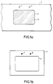
- FIGS 1a, 1b and 1c illustrate the principle of the method according to the invention.
- Figure la shows a document 5, fixed on a first plastic cover 3, a strip of plastic for example. At least two marks 1, 2, for example punctual, are made on the first cover 3.
- the positions of the first marks 1, 2 are previously defined with respect to a first cutting line 4 which is the line of cutting of document 5 to be laminated, this document being previously cut from a sheet.
- the document is attached to the first cover 3, preferably inside the cutting line 4. This can be achieved for example by placing the first cover 3 just out of a matrix of cutting of document 5. It is not compulsory that document 5 remains at inside its cutting line 4, however its position on the first cover 3 is defined with respect to the cutting line 4.
- a second plastic cover is attached to the back of the document 5.
- the second cover is fixed after the completion of the first marks, it is placed so as not to hide them. If the second cover is fixed before the first marks are achieved, these can for example be made on both covers at the same time.
- the fixing of covers on the document can for example be carried out by points of heater.
- Figure 1b shows a second cutting line 6 which is the cutting line of the assembly constituted by the document and its two plastic covers.
- This second cutting line 6 is not example formed by the edges of a die or a cutting punch.
- the position of the second cutting line 6 is fixed and defined with respect to at least two second marks 7, 8 for example located on a cutting module 9 comprising the second cutting line 6. These two marks 7, 8 are by punctual examples.
- the relative positions of the second marks 7, 8 are identical to the relative positions of the first marks 1, 2.
- FIG. 1c shows the superposition of the cutting module 9 and of the entire document 5 and its plastic covers, one of which only 3 is shown.
- the second cutting line 6 of the assembly 3, 5 frames the first cutting line 4 of the document.
- the cutting of the entire document and its covers is only carried out when there is agreement between the first marks 1, 2 and the second marks 7, 8, the positions of the first marks 1, 2 relative to the first cutting line 4 and the position of the second cutting line 6 by relative to the positions of the second references 7, 8 having been defined so as to get that regularity.
- these positions could previously be defined so as to obtain a different placement of the document by in relation to its plastic protection, so as for example to obtain plastic edges of different widths from side to side.
- the first one cutting line 4 can be for example inside the second line of cutout 6 as illustrated in Figure 1c.
- the second cutting line 6 can also, for example, be inside the first cutting line 4, in this case the document is cut again.
- the positions of the first marks on the first plastic cover can be any compared to the first cutting line 4, the document cutting line 5, provided that these positions are fixed and defined with respect to this first line of cutout 4.
- the first marks can for example be inside the latter, therefore inside document 5.
- the first 1, 2 and seconds 7, 8 marks can be for example holes or points marking.
- Figures 2a to 2d illustrate an example of implementation possible of the method according to the invention.
- Figure 2a shows a sheet 21 placed between a first punch 22 for cutting and its associated die 23.
- the cutting of the document 5 contained on the sheet 21 is obtained by passing of the first punch 22 through its die 23, the document 5 being placed between these last two.
- At the first punch 22 are coupled two punches auxiliaries of which only one 24 is shown, the other being hidden by the latter.
- the positions of the auxiliary punches 24 and of the first punch 22 are fixed to each other in a plane perpendicular to their common direction of displacement.
- the first plastic cover 3 to be attached to the front of document 5 is for example placed just below, in contact, the matrix 23 so that at the output of the latter, the document 5 pushed by the first punch 22, be placed directly on this first cover 3. This allows you to keep the position of the document 5 inside its cutting line 4 formed by the edges in opposite the first punch 22 and its die 23.
- a heating element 25 located at proximity and below it allows for example to fix it on the document by a heating point, the total plasticization of the front of the document that can for example be produced later.
- the first cover 3 is for example a plastic strip whose adhesion side, facing the document to be laminated, is by example in polyethylene, and the outer face of which is for example in polyester, the temperature of the latter material not being sensitive to sealing temperature of the adhesion face. Coverage can be in any other heat-sealable plastic material, for example by means of systems known to those skilled in the art.
- the first cover 3 consists of a plastic strip running under the matrix 23, the strip cannot be located just below, in contact with the matrix 23 for reasons of friction in particular. A spacing being formed between the matrix and the strip, it is then possible to provide a system raising this strip at the time of the output of a document from the matrix 23, the strip then being in contact with the latter at the time of drop the document.
- the auxiliary punches 24 move in the same direction as the first punch 22 so as to drill two holes in the first cover 3 as illustrated in Figure 2b, these holes acting as first marks 1, 2 above.
- Figure 2c illustrates an example of positioning a second plastic cover 3 'on the back of document 5, the holes 1, 2 having been made on the first cover 3 and the latter being fixed to the front of the document 5.
- the second cover 3 ′ is for example fixed on the document 5 so as not to cover the holes 1, 2 and to completely cover the document.
- Figure 2d illustrates the positioning of the assembly consisting of document 5 and its two covers 3, 3 'just before cutting this together by a second punch 26 and its associated matrix 27.
- the assembly 5, 3, 3 ' is positioned so that the holes 1, 2 previously performed are committed around studs of which only one 7, 8 is shown, the other being hidden by the latter.
- These studs have a diameter substantially equal to that of the holes. They are fixed relative to the projection of the line of cut out 6 of the assembly in a plane perpendicular to the direction of displacement of the second punch 26, this cutting line 6 being defined by the edges opposite the second punch 26 and its matrix 27.
- the two studs 7, 8 are for example mechanically integral with this matrix 27. These two studs act as second references 7, 8 above.
- the holes 1, 2 and the pads 7, 8 having relative positions identical to each other, the positions of holes 1, 2 and therefore of auxiliary punches 24 relative to the first punch 22 and the positions of the pads 7, 8 relative to the second punch 26 or to its associated matrix 27 are such that they allow for example the obtaining of plastic edges around the document 5.
- FIGS. 3a and 3b illustrate a case of application of the method according to the invention where the documents to be laminated 5 are fixed afterwards, after cutting, on a first plastic strip 3 as shown in FIG. 3a, the strip moving for example under a cutting system of the type of that of Figure 2a. Holes 1, 2 are made simultaneously with the fixing of the front of each document 5 on the tape. A second 3 'plastic strip is attached to the back of the documents 5 by covering them without covering the holes 1, 2. These are for example carried out in accordance with the method above relating to Figures 2a and 2b.
- Figure 3b shows the cutting of plasticized documents, say documents 5 and plastic tapes 3, 3 'as presented by Figure 3a.
- the cutting die 27 associated with the second punch 26 is shown above the strips 3, 3 ', a document 5 being ready to be cut with the plastic strips 3, 3 '.
- the pads 7, 8 secured mechanically from the matrix 27 are engaged in the holes associated with the document to be cut so that this document 5 is good, for example centered in the middle of the cutting line 6. After passing through the matrix 27, holes 31 appear in the bands 3, 3 'corresponding to the location of the cut plastic documents.
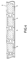
- Figure 4 shows another possible position of the holes 1, 2 on the first plastic strip 3. These are for example made between documents 5.
- the second plastic strip 3 ' for example has holes of dimensions greater than the preceding 1, 2 so that this second strip does not cover the holes 1, 2 made in the first strip 3.
- Holes 1, 2 can still be placed differently on the first plastic strip 3. They can in particular be placed inside from document 5 if space is required on the tape, for the purpose economy for example.
- the method according to the invention is applicable for example if a document is laminated on one side, a second cover in plastic not being then attached to the back of the document.
- plastic cover and document can for example be cut out so that they are edge to edge.
- the aforementioned point markers 1, 2, 7, 8 can be included in landmarks that cannot be reduced to points such as holes or circular punches in particular.
- marks 7, 8 can be included in a rectangular section punch and the marks correspondents 1, 2 can be included in a rectangular hole matching the shape of the punch with rectangular section.
- Markers 1, 2 made in the first plastic cover 3 and marks 7, 8 linked to the second line cutting 6 can therefore be for example respectively included in a single mark produced on the first cover 3 and a single mark linked to the second cutting line 6, the cutting of the plastic document taking place when there is agreement between these two landmarks only.
Landscapes
- Lining Or Joining Of Plastics Or The Like (AREA)
- Perforating, Stamping-Out Or Severing By Means Other Than Cutting (AREA)
- Laminated Bodies (AREA)
- Collation Of Sheets And Webs (AREA)
Claims (5)
- Verfahren zum Einschweißen eines Dokuments in Kunststoff, bei dem ein Dokument (5) durch erste Ausschneidemittel (22, 23) aus einem Blatt (21) ausgeschnitten wird, dann auf einer Kunststoffschutzfolie (3) angebracht wird, um eine Einheit (3, 5) zu bilden, und die Einheit durch zweite Ausschneidemittel (26, 27) jedesmal dann ausgeschnitten wird, wenn es eine Übereinstimmung zwischen ersten Paßmarkierungen (1, 2) und zweiten Paßmarkierungen (7, 8) gibt, und darüber hinauswährend eines ersten Schritts das das Dokument (5) tragende Blatt (21) zwischen einen ersten Stempel (22) und seine dazugehörige Matrix (23) gesetzt wird, wobei das Dokument (5) entsprechend einer ersten Schnittlinie (4) beim Lauf des Stempels (22) durch die Matrix (23) ausgeschnitten wird, um auf der Kunststoffschutzfolie (3) aufgenommen zu werden, die in Kontakt zur Matrix (23) oder in unmittelbarer Nähe unter der Matrix (23) angeordnet ist, und gleichzeitig sich zwei Hilfsstempel (24) zur und durch die Schutzfolie (3) bewegen, um wenigstens zwei Löcher (1, 2) in der Schutzfolie zu erzeugen, wobei die Position der Hilfsstempel (24) in einer Ebene festgelegt ist, die senkrecht zur Bewegungsrichtung des ersten Stempels (22) liegt, und die Löcher (1, 2) die ersten Paßmarkierungen darstellen, deren Position in Beziehung zu der ersten Schnittlinie definiert ist, und das Dokument (5) auf der Schutzfolie (3) angebracht ist, um die zu zerschneidende Einheit (3, 5) zu bilden; undwährend eines zweiten Schritts die Einheit (3, 5) entsprechend einer zweiten Schnittlinie (6) ausgeschnitten wird, deren Position in Beziehung zu den zweiten Paßmarkierungen (7, 8) definiert ist, die in Übereinstimmung zu den ersten Paßmarkierungen zugeführt werden, wobei die Einheit unter Ausübung von Druck und Einwirkung von Wärme direkt vor, während oder nach dem Ausschneiden entsprechend der zweiten Schnittlinie gewalzt wird.
- Verfahren nach Anspruch 1, dadurch gekennzeichnet, daß eine zweite Kunststoffschutzfolie (3') auf der der ersten Schutzfolie (3) gegenüberliegenden Seite des Dokuments (5) in der Weise angebracht wird, daß sie die zwei in der letzteren erzeugten Paßmarkierungen (1, 2) nicht bedeckt, wobei das Dokument (5) und die zwei Schutzfolien (3, 3') die zu zerschneidende Einheit bilden.
- Verfahren nach einem der vorhergehenden Ansprüche, dadurch gekennzeichnet, daß die zweiten Ausschneidemittel einen zweiten Stempel (26) und seine dazugehörige Matrix (27) umfassen und die zweiten Paßmarkierungen durch wenigstens zwei Stifte (7, 8) gebildet werden, die mechanisch aus einem Stück mit der Matrix (27) gebildet sind, wobei das Ausschneiden dann erfolgt, wenn die Stifte (7, 8) in die Löcher (1, 2) eingreifen.
- Verfahren nach einem der vorhergehenden Ansprüche, dadurch gekennzeichnet, daß die Kunststoffschutzfolie (3) aus einem Kunststoffband besteht, auf dem hintereinander mehrere Dokumente (5) angebracht sind.
- Verfahren nach Anspruch 4, dadurch gekennzeichnet, daß die Löcher (1, 2) zwischen den Dokumenten (5) hergestellt sind.
Applications Claiming Priority (2)
| Application Number | Priority Date | Filing Date | Title |
|---|---|---|---|
| FR9215083 | 1992-12-15 | ||
| FR9215083A FR2699109B1 (fr) | 1992-12-15 | 1992-12-15 | Procédé de plastification de documents découpés dans une feuille. |
Publications (2)
| Publication Number | Publication Date |
|---|---|
| EP0603035A1 EP0603035A1 (de) | 1994-06-22 |
| EP0603035B1 true EP0603035B1 (de) | 1999-04-07 |
Family
ID=9436595
Family Applications (1)
| Application Number | Title | Priority Date | Filing Date |
|---|---|---|---|
| EP19930402984 Expired - Lifetime EP0603035B1 (de) | 1992-12-15 | 1993-12-10 | Verfahren zum Einschweissen von Dokumenten, geschnitten aus folienförmigem Material |
Country Status (7)
| Country | Link |
|---|---|
| US (1) | US5474636A (de) |
| EP (1) | EP0603035B1 (de) |
| JP (1) | JPH06210731A (de) |
| AT (1) | ATE178530T1 (de) |
| DE (1) | DE69324336T2 (de) |
| ES (1) | ES2131565T3 (de) |
| FR (1) | FR2699109B1 (de) |
Families Citing this family (6)
| Publication number | Priority date | Publication date | Assignee | Title |
|---|---|---|---|---|
| DE4442920C2 (de) * | 1994-12-02 | 2001-02-22 | Heraeus Gmbh W C | Verfahren zur Herstellung eines Folienverbundes |
| DE19500820A1 (de) * | 1995-01-13 | 1996-07-18 | Melzer Maschinenbau Gmbh | Verfahren zum Herstellen von Kunststoffkarten |
| US5783024A (en) * | 1996-04-12 | 1998-07-21 | Nbs Imaging Systems, Inc. | Apparatus for applying heat bondable lamina to a substrate |
| WO2002028621A2 (en) * | 2000-10-03 | 2002-04-11 | Fargo Electronics, Inc. | Overlaminate patch having improved security and method for its manufacture |
| US7383999B2 (en) | 2004-12-28 | 2008-06-10 | Digimarc Corporation | ID document structure with pattern coating providing variable security features |
| DE102008026231B4 (de) * | 2008-05-29 | 2016-08-04 | Bundesdruckerei Gmbh | Folienstapel aus Folien und Verfahren zum Laminieren der Folien |
Family Cites Families (11)
| Publication number | Priority date | Publication date | Assignee | Title |
|---|---|---|---|---|
| US2857966A (en) * | 1956-03-14 | 1958-10-28 | Wean Equipment Corp | Shearing sheets from continuously advancing strip |
| AT346630B (de) * | 1976-12-29 | 1978-11-27 | Gao Ges Automation Org | Mehrschichtiger randverschweisster aufzeichnungstraeger und verfahren zur herstellung eines verbundinletts fuer diesen aufzeichnungstraeger |
| DE2853893A1 (de) * | 1978-12-14 | 1980-06-26 | Hoechst Ag | Verfahren zur herstellung von identifikationskarten |
| DE3028052C2 (de) * | 1980-07-24 | 1983-11-10 | Held, Kurt, 7218 Trossingen | Vorrichtung zum kontinuierlichen Einsiegeln von Einlegeteilen |
| DE3130071A1 (de) * | 1981-07-30 | 1983-02-17 | Agfa-Gevaert Ag, 5090 Leverkusen | Faelschungssicheres dokument und verfahren zu seiner herstellung |
| DE3232060C2 (de) * | 1981-09-09 | 1984-08-30 | Fis Organisation GmbH, 2000 Hamburg | Verfahren zur Herstellung eines einstückigen maschinenlesbaren Informationsträgers und Zwischenprodukt hierfür |
| US5019314A (en) * | 1985-12-16 | 1991-05-28 | Almetek Industries, Inc. | Process for die cutting plastic sheets |
| US4999065A (en) * | 1986-01-08 | 1991-03-12 | Lasercard Company L.P. | Method of making an identification card |
| US4696210A (en) * | 1986-06-30 | 1987-09-29 | Chief Technology Systems, Inc. | Two hole automatic precision punch |
| JPH0750094B2 (ja) * | 1987-01-28 | 1995-05-31 | 富士写真フイルム株式会社 | 化学分析スライドの連続製造方法 |
| DE3913604A1 (de) * | 1989-04-25 | 1990-12-06 | Gao Ges Automation Org | Verfahren und vorrichtung zum aufbringen von unterschriftsstreifen auf ausweiskarten |
-
1992
- 1992-12-15 FR FR9215083A patent/FR2699109B1/fr not_active Expired - Fee Related
-
1993
- 1993-12-03 US US08/160,905 patent/US5474636A/en not_active Expired - Fee Related
- 1993-12-09 JP JP34036893A patent/JPH06210731A/ja active Pending
- 1993-12-10 ES ES93402984T patent/ES2131565T3/es not_active Expired - Lifetime
- 1993-12-10 AT AT93402984T patent/ATE178530T1/de not_active IP Right Cessation
- 1993-12-10 EP EP19930402984 patent/EP0603035B1/de not_active Expired - Lifetime
- 1993-12-10 DE DE69324336T patent/DE69324336T2/de not_active Expired - Fee Related
Also Published As
| Publication number | Publication date |
|---|---|
| ES2131565T3 (es) | 1999-08-01 |
| US5474636A (en) | 1995-12-12 |
| DE69324336D1 (de) | 1999-05-12 |
| EP0603035A1 (de) | 1994-06-22 |
| DE69324336T2 (de) | 1999-09-09 |
| JPH06210731A (ja) | 1994-08-02 |
| ATE178530T1 (de) | 1999-04-15 |
| FR2699109B1 (fr) | 1995-01-06 |
| FR2699109A1 (fr) | 1994-06-17 |
Similar Documents
| Publication | Publication Date | Title |
|---|---|---|
| US4285999A (en) | Method and apparatus involving adhesive backed photographs | |
| EP0603035B1 (de) | Verfahren zum Einschweissen von Dokumenten, geschnitten aus folienförmigem Material | |
| US5405470A (en) | Method and device for splicing two thin webs of material | |
| CA1132164A (fr) | Dispositif pour le transfert a sec de signes en encre | |
| EP0598042B1 (de) | Vorrichtung und verfahren zum verbinden von zwei dünnen materialbahnen | |
| EP3126152B1 (de) | Dokument mit einer sicherheitsvorrichtung für vertrauliche informationen die im dokument enthalten ist und verfahren zum einsatz besagter vorrichtung | |
| EP0624465B1 (de) | Vorrichtung zum zeitweiligen Verschweissen von Dokumenten auf einer Kunststoffbahn | |
| EP1986869A2 (de) | Film zur übertragung von mindestens einer markierung auf mindestens ein substrat zur sicherung, verfahren zur herstellung und übertragung eines derartigen übertragungsfilms | |
| US4586975A (en) | Method of and apparatus for facilitating the automatic processing of checks | |
| US7169247B2 (en) | Methods and apparatus for laminating documents | |
| EP1928671B1 (de) | Sicherheitsmarkierungssystem | |
| US20020085182A1 (en) | Simplified self-developing film assemblages and methods of making the sam | |
| US6502341B1 (en) | Cardboard-plastic slide mount | |
| KR0177557B1 (ko) | 점착식 앨범대지의 제조장치, 제조방법 및 점착대지 | |
| US6370804B1 (en) | Cardboard-plastic slide mount | |
| EP0925956B1 (de) | Verfahren und System zum Herstellen von Sicherheitsdokumenten | |
| FR2541631A1 (fr) | Cahier de feuilles tel que periodique contenant un objet separable et procede pour obtenir un tel cahier | |
| JP2003005342A (ja) | スプライス形成装置およびスプライス形成方法 | |
| FR3058990A1 (fr) | Dispositif pour appliquer manuellement une etiquette sur un objet predetermine, et procede d'application d'etiquette a l'aide d'un tel dispositif | |
| EP0384891B1 (de) | Verfahren und Maschine zur Herstellung von selbstklebenden Gegenständen und solche Gegenstände | |
| US7374803B2 (en) | Band-like matter fastening seal, roll photo film, apparatus and methods for manufacturing a band-like matter unit | |
| FR3139173A1 (fr) | Support d’etiquette electronique rfid en partie reutilisable | |
| US20050199330A1 (en) | Device and method for the application of a sheet-like jointing means onto a contact area of a wafer | |
| FR2613086A2 (fr) | Automate pour produire en temps reel des nouvelles cartes de securite et procedes d'obtention de la base de ces cartes | |
| FR2798878A1 (fr) | Dispositif et procede pour positionner un couteau par rapport a son contre-couteau |
Legal Events
| Date | Code | Title | Description |
|---|---|---|---|
| PUAI | Public reference made under article 153(3) epc to a published international application that has entered the european phase |
Free format text: ORIGINAL CODE: 0009012 |
|
| AK | Designated contracting states |
Kind code of ref document: A1 Designated state(s): AT BE CH DE DK ES FR GB GR IE IT LI LU NL PT SE |
|
| 17P | Request for examination filed |
Effective date: 19940922 |
|
| 17Q | First examination report despatched |
Effective date: 19970819 |
|
| GRAG | Despatch of communication of intention to grant |
Free format text: ORIGINAL CODE: EPIDOS AGRA |
|
| GRAG | Despatch of communication of intention to grant |
Free format text: ORIGINAL CODE: EPIDOS AGRA |
|
| GRAH | Despatch of communication of intention to grant a patent |
Free format text: ORIGINAL CODE: EPIDOS IGRA |
|
| GRAH | Despatch of communication of intention to grant a patent |
Free format text: ORIGINAL CODE: EPIDOS IGRA |
|
| GRAA | (expected) grant |
Free format text: ORIGINAL CODE: 0009210 |
|
| AK | Designated contracting states |
Kind code of ref document: B1 Designated state(s): AT BE CH DE DK ES FR GB GR IE IT LI LU NL PT SE |
|
| PG25 | Lapsed in a contracting state [announced via postgrant information from national office to epo] |
Ref country code: SE Free format text: THE PATENT HAS BEEN ANNULLED BY A DECISION OF A NATIONAL AUTHORITY Effective date: 19990407 Ref country code: NL Free format text: LAPSE BECAUSE OF FAILURE TO SUBMIT A TRANSLATION OF THE DESCRIPTION OR TO PAY THE FEE WITHIN THE PRESCRIBED TIME-LIMIT Effective date: 19990407 Ref country code: GR Free format text: LAPSE BECAUSE OF NON-PAYMENT OF DUE FEES Effective date: 19990407 Ref country code: AT Free format text: LAPSE BECAUSE OF FAILURE TO SUBMIT A TRANSLATION OF THE DESCRIPTION OR TO PAY THE FEE WITHIN THE PRESCRIBED TIME-LIMIT Effective date: 19990407 |
|
| REF | Corresponds to: |
Ref document number: 178530 Country of ref document: AT Date of ref document: 19990415 Kind code of ref document: T |
|
| REG | Reference to a national code |
Ref country code: CH Ref legal event code: EP |
|
| REG | Reference to a national code |
Ref country code: IE Ref legal event code: FG4D Free format text: FRENCH |
|
| REF | Corresponds to: |
Ref document number: 69324336 Country of ref document: DE Date of ref document: 19990512 |
|
| GBT | Gb: translation of ep patent filed (gb section 77(6)(a)/1977) |
Effective date: 19990602 |
|
| PG25 | Lapsed in a contracting state [announced via postgrant information from national office to epo] |
Ref country code: PT Free format text: LAPSE BECAUSE OF FAILURE TO SUBMIT A TRANSLATION OF THE DESCRIPTION OR TO PAY THE FEE WITHIN THE PRESCRIBED TIME-LIMIT Effective date: 19990707 Ref country code: DK Free format text: LAPSE BECAUSE OF FAILURE TO SUBMIT A TRANSLATION OF THE DESCRIPTION OR TO PAY THE FEE WITHIN THE PRESCRIBED TIME-LIMIT Effective date: 19990707 |
|
| REG | Reference to a national code |
Ref country code: ES Ref legal event code: FG2A Ref document number: 2131565 Country of ref document: ES Kind code of ref document: T3 |
|
| NLV1 | Nl: lapsed or annulled due to failure to fulfill the requirements of art. 29p and 29m of the patents act | ||
| PG25 | Lapsed in a contracting state [announced via postgrant information from national office to epo] |
Ref country code: IE Free format text: LAPSE BECAUSE OF NON-PAYMENT OF DUE FEES Effective date: 19991206 |
|
| PG25 | Lapsed in a contracting state [announced via postgrant information from national office to epo] |
Ref country code: LU Free format text: LAPSE BECAUSE OF NON-PAYMENT OF DUE FEES Effective date: 19991210 |
|
| PG25 | Lapsed in a contracting state [announced via postgrant information from national office to epo] |
Ref country code: LI Free format text: LAPSE BECAUSE OF NON-PAYMENT OF DUE FEES Effective date: 19991231 Ref country code: CH Free format text: LAPSE BECAUSE OF NON-PAYMENT OF DUE FEES Effective date: 19991231 |
|
| REG | Reference to a national code |
Ref country code: IE Ref legal event code: FD4D |
|
| PLBE | No opposition filed within time limit |
Free format text: ORIGINAL CODE: 0009261 |
|
| STAA | Information on the status of an ep patent application or granted ep patent |
Free format text: STATUS: NO OPPOSITION FILED WITHIN TIME LIMIT |
|
| 26N | No opposition filed | ||
| PGFP | Annual fee paid to national office [announced via postgrant information from national office to epo] |
Ref country code: DE Payment date: 20011119 Year of fee payment: 9 |
|
| PGFP | Annual fee paid to national office [announced via postgrant information from national office to epo] |
Ref country code: GB Payment date: 20011122 Year of fee payment: 9 |
|
| PGFP | Annual fee paid to national office [announced via postgrant information from national office to epo] |
Ref country code: FR Payment date: 20011218 Year of fee payment: 9 |
|
| PGFP | Annual fee paid to national office [announced via postgrant information from national office to epo] |
Ref country code: ES Payment date: 20011228 Year of fee payment: 9 |
|
| REG | Reference to a national code |
Ref country code: GB Ref legal event code: IF02 |
|
| PGFP | Annual fee paid to national office [announced via postgrant information from national office to epo] |
Ref country code: BE Payment date: 20020121 Year of fee payment: 9 |
|
| REG | Reference to a national code |
Ref country code: FR Ref legal event code: CD |
|
| PG25 | Lapsed in a contracting state [announced via postgrant information from national office to epo] |
Ref country code: GB Free format text: LAPSE BECAUSE OF NON-PAYMENT OF DUE FEES Effective date: 20021210 |
|
| PG25 | Lapsed in a contracting state [announced via postgrant information from national office to epo] |
Ref country code: ES Free format text: LAPSE BECAUSE OF NON-PAYMENT OF DUE FEES Effective date: 20021211 |
|
| PG25 | Lapsed in a contracting state [announced via postgrant information from national office to epo] |
Ref country code: BE Free format text: LAPSE BECAUSE OF NON-PAYMENT OF DUE FEES Effective date: 20021231 |
|
| BERE | Be: lapsed |
Owner name: *THOMSON-CSF Effective date: 20021231 |
|
| PG25 | Lapsed in a contracting state [announced via postgrant information from national office to epo] |
Ref country code: DE Free format text: LAPSE BECAUSE OF NON-PAYMENT OF DUE FEES Effective date: 20030701 |
|
| GBPC | Gb: european patent ceased through non-payment of renewal fee | ||
| PG25 | Lapsed in a contracting state [announced via postgrant information from national office to epo] |
Ref country code: FR Free format text: LAPSE BECAUSE OF NON-PAYMENT OF DUE FEES Effective date: 20030901 |
|
| REG | Reference to a national code |
Ref country code: FR Ref legal event code: ST |
|
| REG | Reference to a national code |
Ref country code: ES Ref legal event code: FD2A Effective date: 20021211 |
|
| PG25 | Lapsed in a contracting state [announced via postgrant information from national office to epo] |
Ref country code: IT Free format text: LAPSE BECAUSE OF NON-PAYMENT OF DUE FEES;WARNING: LAPSES OF ITALIAN PATENTS WITH EFFECTIVE DATE BEFORE 2007 MAY HAVE OCCURRED AT ANY TIME BEFORE 2007. THE CORRECT EFFECTIVE DATE MAY BE DIFFERENT FROM THE ONE RECORDED. Effective date: 20051210 |