EP0603041A1 - Herstellung der Stirnfläche einer optischen Faser mit Mehrfachlinse zur optischen Kupplung - Google Patents
Herstellung der Stirnfläche einer optischen Faser mit Mehrfachlinse zur optischen Kupplung Download PDFInfo
- Publication number
- EP0603041A1 EP0603041A1 EP93402994A EP93402994A EP0603041A1 EP 0603041 A1 EP0603041 A1 EP 0603041A1 EP 93402994 A EP93402994 A EP 93402994A EP 93402994 A EP93402994 A EP 93402994A EP 0603041 A1 EP0603041 A1 EP 0603041A1
- Authority
- EP
- European Patent Office
- Prior art keywords
- fiber
- lenses
- lens
- curvature
- optical fiber
- Prior art date
- Legal status (The legal status is an assumption and is not a legal conclusion. Google has not performed a legal analysis and makes no representation as to the accuracy of the status listed.)
- Ceased
Links
- 239000013307 optical fiber Substances 0.000 title claims abstract description 34
- 230000008878 coupling Effects 0.000 title claims abstract description 22
- 238000010168 coupling process Methods 0.000 title claims abstract description 22
- 238000005859 coupling reaction Methods 0.000 title claims abstract description 22
- 238000002360 preparation method Methods 0.000 title description 2
- 239000000835 fiber Substances 0.000 claims abstract description 84
- 238000000034 method Methods 0.000 claims abstract description 18
- 238000000151 deposition Methods 0.000 claims abstract description 6
- 230000003287 optical effect Effects 0.000 claims description 11
- 230000004927 fusion Effects 0.000 claims description 9
- 238000003466 welding Methods 0.000 claims description 6
- 238000010891 electric arc Methods 0.000 description 6
- 230000009471 action Effects 0.000 description 5
- 229920006240 drawn fiber Polymers 0.000 description 5
- 229920000297 Rayon Polymers 0.000 description 4
- 239000011521 glass Substances 0.000 description 4
- 239000002964 rayon Substances 0.000 description 4
- 238000010438 heat treatment Methods 0.000 description 3
- 230000006872 improvement Effects 0.000 description 3
- 235000014820 Galium aparine Nutrition 0.000 description 2
- 240000005702 Galium aparine Species 0.000 description 2
- 230000008901 benefit Effects 0.000 description 2
- 235000012830 plain croissants Nutrition 0.000 description 2
- 230000008569 process Effects 0.000 description 2
- 230000005855 radiation Effects 0.000 description 2
- 238000012360 testing method Methods 0.000 description 2
- 241001415961 Gaviidae Species 0.000 description 1
- 238000005452 bending Methods 0.000 description 1
- 238000003776 cleavage reaction Methods 0.000 description 1
- 238000005520 cutting process Methods 0.000 description 1
- 230000003247 decreasing effect Effects 0.000 description 1
- 230000000977 initiatory effect Effects 0.000 description 1
- 238000004519 manufacturing process Methods 0.000 description 1
- 229910052594 sapphire Inorganic materials 0.000 description 1
- 239000010980 sapphire Substances 0.000 description 1
- 230000007017 scission Effects 0.000 description 1
- 239000004065 semiconductor Substances 0.000 description 1
- VLCQZHSMCYCDJL-UHFFFAOYSA-N tribenuron methyl Chemical compound COC(=O)C1=CC=CC=C1S(=O)(=O)NC(=O)N(C)C1=NC(C)=NC(OC)=N1 VLCQZHSMCYCDJL-UHFFFAOYSA-N 0.000 description 1
Images


Classifications
-
- G—PHYSICS
- G02—OPTICS
- G02B—OPTICAL ELEMENTS, SYSTEMS OR APPARATUS
- G02B6/00—Light guides; Structural details of arrangements comprising light guides and other optical elements, e.g. couplings
- G02B6/24—Coupling light guides
- G02B6/42—Coupling light guides with opto-electronic elements
- G02B6/4201—Packages, e.g. shape, construction, internal or external details
- G02B6/4202—Packages, e.g. shape, construction, internal or external details for coupling an active element with fibres without intermediate optical elements, e.g. fibres with plane ends, fibres with shaped ends, bundles
- G02B6/4203—Optical features
-
- G—PHYSICS
- G02—OPTICS
- G02B—OPTICAL ELEMENTS, SYSTEMS OR APPARATUS
- G02B6/00—Light guides; Structural details of arrangements comprising light guides and other optical elements, e.g. couplings
- G02B6/24—Coupling light guides
- G02B6/255—Splicing of light guides, e.g. by fusion or bonding
- G02B6/2552—Splicing of light guides, e.g. by fusion or bonding reshaping or reforming of light guides for coupling using thermal heating, e.g. tapering, forming of a lens on light guide ends
-
- G—PHYSICS
- G02—OPTICS
- G02B—OPTICAL ELEMENTS, SYSTEMS OR APPARATUS
- G02B6/00—Light guides; Structural details of arrangements comprising light guides and other optical elements, e.g. couplings
- G02B6/24—Coupling light guides
- G02B6/42—Coupling light guides with opto-electronic elements
- G02B6/4201—Packages, e.g. shape, construction, internal or external details
- G02B6/4204—Packages, e.g. shape, construction, internal or external details the coupling comprising intermediate optical elements, e.g. lenses, holograms
- G02B6/4206—Optical features
Definitions
- the present invention relates to the field of optical fibers intended to be coupled with a phototransducer.
- the expression “phototransducer” groups the receiving optical systems able to transform an optical signal received from an optical fiber into an electrical signal, and the emitting optical systems able to generate an optical signal towards an optical fiber.
- These optical systems can be formed of optical integrated circuits.
- an optical fiber 10 can be distinguished comprising a core 12 surrounded by a sheath 14, as well as a phototransducer 20 aligned with the core 12, and a microlens 30 added by welding on a cleaved end face 16 of the optical fiber 10, facing the core 12.
- the present invention now aims to improve the known prior systems.
- the present invention also relates to the systems obtained by implementing this method.
- FIG. 3 appended there is a single mode fiber 100 comprising a sheath 108 which surrounds the aforementioned core 106.
- the sheath 108 typically has a diameter of the order of 125 ⁇ m, while the core 106 typically has a diameter of the order of 9 ⁇ m.
- the phototransducer is referenced 300.
- the step of cleaving the optical fiber 100 consists in cutting said fiber so that its resulting end face 102 is at least substantially planar and orthogonal to its central axis 104.
- the surface of this cleaved end face 102 is therefore equal to the cross section of the core 106 and the sheath 108 which surrounds it.
- This cleavage step can be carried out according to any sectioning process known to a person skilled in the art, if necessary, by simple bending of the fiber 100 until abrupt rupture of the latter after initiation of rupture using with a very hard edge.
- the procedure is preferably as follows.
- a small piece of another fiber 200 is stretched (traction T) coaxially and symmetrically until it breaks at a point 202, under the action of an electric arc.
- the piece of fiber 200 can for example have a length of the order of ten cm.
- the drawn fiber 200 is preferably of the same kind as the cleaved fiber 100. At the end of the stretching step, two ends of optical fiber 200 are thus obtained, each having a tapered tapered end.
- a stretched end of optical fiber 200 is then placed opposite the cleaved end 102 of the fiber 100 and aligned thereon, as shown in FIG. 5.
- This alignment can be carried out by any suitable means, for example by placing the fiber 100 cleaved and the stretched fiber end 200, on suitable V-shaped supports.
- Known optical fiber splicing techniques commonly use such V-shaped sapphire supports, having an accuracy of the order of ⁇ m. For this reason, these V-shaped supports are not shown in the appended figures and will not be described in more detail below.
- the tip of the drawn fiber 200 is then brought into mechanical contact with the core 106 of the cleaved fiber 100, and this under a slight axial pressure P, as shown in FIG. 6, while maintaining the previous alignment between the drawn fiber 200 and the cleaved fiber 100.
- the assembly obtained is subjected to an electric arc, as shown in FIG. 7, in order to obtain a rapid and low-intensity fusion of the tip of the drawn fiber 200.
- This fiber 200 is removed as soon as the appearance of the welding of this tip on the core 106 of the cleaved fiber 100.
- This withdrawal of the drawn fiber 200 leads to the release of a glass needle 210 centered on the axis 104 and linked to the core 106 of the cleaved fiber 100, as shown in FIG. 8.
- An optical fiber 100 is then obtained comprising a cleaved end 102 and a lens 220 attached by welding to this cleaved end opposite the core 106 of the optical fiber 100.
- step a) of drawing a new piece of optical fiber the taper of the point obtained by drawing must be controlled in order to be able to release, in step d), a needle of suitable size compatible with the desired radius of curvature for the new lens.
- microsolder of the "micro fusion splicer ms-1.008" type sold by the company FOUNDATION INSTRUMENTS. Such a microsealer generates an electric arc.
- electric arc heating is however not compulsory. It can be replaced for example by a heating using a laser power source provided that care is taken to respect a precise alignment between the cleaved fiber 100 and the drawn end 200 which brings the microlens 220 on the heart 106, and that care is taken to produce a very rapid local fusion of the tip 200 in order to weld onto the core 106 of the cleaved fiber 100 a glass needle 210 of appropriate size.
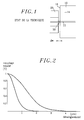
- the inventors first determined that in a conventional system with a simple hemispherical lens, the radius of this lens directly conditions the position and the height of the maximum coupling obtained as a function of the transducer / fiber distance, along the axis of that here, for a determined angular opening of the beam. More precisely, a simple hemispherical lens, of very small radius of curvature (for example less than 8 ⁇ m) can collect a maximum of light only if the distance transducer / lens remains sufficiently small so that the emission cone coincides with the numerical aperture of the lens (as shown schematically in Figure 1).
- the smallest lens that is to say the lens 220 having the smallest radius of curvature, which also corresponds to the lens furthest from the cleaved face 102 of optical fiber, collects the central part of the emitted beam corresponding to the maximum energy of a Gaussian beam.
- the next lens 220 is interested up to its periphery in the part of the beam not obscured by the previous one, and so on in the hypothesis of a succession of lenses of decreasing curvature (or rays increasing curvature) closer to fiber 100.
- the combination of several lenses conforming to the present invention leads to an appreciable gain in its coupling with a phototransducer 300, if the radii of curvature of the various lenses 220 remain less than ten micrometers, at least for the first two lenses 220.
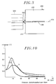
- the curves 10a and 10b represent the values of the coefficient of the coupling C respectively obtained with simple hemispherical lenses 220 deposited facing the heart 106 and having, one a radius of curvature of 4 ⁇ m, the other a radius of 8 ⁇ m curvature.
- the curve identified by the index c in FIG. 10 corresponds to the coupling coefficient obtained using a double lens in accordance with the present invention comprising two lenses with respective radii of curvature of 4 and 8 ⁇ m.
- the present invention is not limited to the use of a double lens 220, as shown in FIG. 3.
- a triple lens 220 is shown opposite the cleaved face 102 of the optical fiber.
- FIG. 12 There is thus shown schematically in FIG. 12 appended, a multimode fiber element with an index gradient 400 interposed between the lens assembly 220 and the single mode fiber 100.
- the core diameter and shape of the gradient characteristics of the multimode fiber with an index gradient 400 condition the periodicity of propagation of the guided light wave.
- a multimode fiber element with an index gradient 400 of adequate calibrated length it is possible to obtain angular input / output couples in perfect correspondence with on one side the lens assembly 220, on the other fiber 100.
- the pieces of fiber 400 and 500 can be fixed in FIG. 100 by conventional splicing, using any known apparatus.
- fibers 100, 400 and 500 of the same diameter are chosen.
- the interposition between the fiber 100 and the collecting optic formed by the lens assembly 220 of a multimode fiber element 400 leads to a focusing optic 220 whose radii of curvature of the lenses this time range between 10 and 100 ⁇ m.
- the optimal distance of the coupling with the phototransducer 300 consequently becomes much less critical, since it then reaches several tens of micrometers.
- the tests carried out by the inventors have shown an increase in coupling coefficient and an improvement in the precision of the phototransducer / fiber alignment, due to the superposition of lenses of increasing curvature.
- the resulting curve with the index c in FIG. 10 shows a higher maximum coupling coefficient, followed by a less pronounced decrease, a sign of better coupling stability with the phototransducer / fiber spacing.
Landscapes
- Physics & Mathematics (AREA)
- General Physics & Mathematics (AREA)
- Optics & Photonics (AREA)
- Engineering & Computer Science (AREA)
- Plasma & Fusion (AREA)
- Optical Couplings Of Light Guides (AREA)
Applications Claiming Priority (2)
| Application Number | Priority Date | Filing Date | Title |
|---|---|---|---|
| FR9215089 | 1992-12-15 | ||
| FR9215089A FR2699292B1 (fr) | 1992-12-15 | 1992-12-15 | Procédé de préparation par lentillage multiple d'une fibre optique en vue d'un couplage optimum avec un phototransducteur et système optique obtenu. |
Publications (1)
| Publication Number | Publication Date |
|---|---|
| EP0603041A1 true EP0603041A1 (de) | 1994-06-22 |
Family
ID=9436601
Family Applications (1)
| Application Number | Title | Priority Date | Filing Date |
|---|---|---|---|
| EP93402994A Ceased EP0603041A1 (de) | 1992-12-15 | 1993-12-13 | Herstellung der Stirnfläche einer optischen Faser mit Mehrfachlinse zur optischen Kupplung |
Country Status (3)
| Country | Link |
|---|---|
| US (1) | US5402510A (de) |
| EP (1) | EP0603041A1 (de) |
| FR (1) | FR2699292B1 (de) |
Cited By (1)
| Publication number | Priority date | Publication date | Assignee | Title |
|---|---|---|---|---|
| FR2747799A1 (fr) * | 1996-04-23 | 1997-10-24 | France Telecom | Procede de realisation d'un dispositif de couplage pour fibre optique |
Families Citing this family (13)
| Publication number | Priority date | Publication date | Assignee | Title |
|---|---|---|---|---|
| US5511140A (en) * | 1994-10-13 | 1996-04-23 | International Business Machines Corporation | Molded plastic optical fiber-optoelectronic converter subassembly |
| US5631991A (en) * | 1996-01-26 | 1997-05-20 | International Business Machines Corporation | Plastic optical subassemblies for light transfer between an optical fiber and an optoelectronic converter and the fabrication of such plastic optical subassemblies |
| US6415087B1 (en) | 1997-06-04 | 2002-07-02 | Corning Laserton, Inc. | Polished fused optical fiber endface |
| US6360039B1 (en) * | 1998-07-17 | 2002-03-19 | Lightpath Technologies, Inc. | Fabrication of collimators employing optical fibers fusion-spliced to optical elements of substantially larger cross-sectional areas |
| US6217698B1 (en) * | 1998-07-17 | 2001-04-17 | Lightpath Technologies, Inc. | Use of a laser to fusion-splice optical components of substantially different cross-sectional areas |
| JP2002536683A (ja) | 1999-02-05 | 2002-10-29 | コーニング インコーポレイテッド | 造形された光学要素を有する光ファイバ部材およびその製造方法 |
| CN1196949C (zh) | 2000-03-17 | 2005-04-13 | 康宁股份有限公司 | 光波导透镜和制造方法 |
| US6552298B1 (en) | 2001-09-28 | 2003-04-22 | Corning Incorporated | Apparatus and method for making a lens on the end of an optical waveguide fiber |
| US6963682B2 (en) * | 2002-03-04 | 2005-11-08 | Corning Incorporated | Beam altering fiber lens device and method of manufacture |
| US7062135B2 (en) * | 2002-03-21 | 2006-06-13 | Corning Incorporated | Method for fabricating curved elements |
| US6979111B2 (en) * | 2002-10-11 | 2005-12-27 | National Christmas Products, Inc. | Fiber optic based light ornament |
| US20170158543A1 (en) * | 2015-12-05 | 2017-06-08 | Spiral Arts, Inc. | Method and Apparatus For Additive Manufacturing of Objects Using Droplets of Molten Glass |
| US10969560B2 (en) | 2017-05-04 | 2021-04-06 | Lightpath Technologies, Inc. | Integrated optical assembly and manufacturing the same |
Citations (8)
| Publication number | Priority date | Publication date | Assignee | Title |
|---|---|---|---|---|
| GB1586188A (en) * | 1977-05-23 | 1981-03-18 | Philips Nv | Optical system |
| JPS58158620A (ja) * | 1982-03-17 | 1983-09-20 | Hitachi Ltd | 光通信装置およびこれに用いる光フアイバならびに光フアイバの加工方法 |
| FR2548391A1 (fr) * | 1983-06-30 | 1985-01-04 | Comp Generale Electricite | Procede de formation d'une lentille de couplage a l'extremite d'une fibre optique sur le coeur de celle-ci |
| JPS60111208A (ja) * | 1983-11-21 | 1985-06-17 | Matsushita Electric Ind Co Ltd | 光ファイバ端面微小レンズの形成方法 |
| DE3407413A1 (de) * | 1984-02-29 | 1985-08-29 | Standard Elektrik Lorenz Ag, 7000 Stuttgart | Lichtwellenleiter mit ankopplungsoptik |
| EP0155379A2 (de) * | 1984-03-02 | 1985-09-25 | Siemens Aktiengesellschaft | Koppelanordnung zum Ankoppeln eines Lichtwellenleiters an einen Halbleiterlaser und Verfahren zur Herstellung einer solchen Anordnung |
| EP0260742A1 (de) * | 1986-09-10 | 1988-03-23 | Koninklijke Philips Electronics N.V. | Optische Nachrichtenfaser mit verjüngtem Ende und zugeordneter Linse |
| US4867776A (en) * | 1988-05-02 | 1989-09-19 | Compaq Computer Corporation | Apparatus for and method of forming integral lenses on optical fibers |
Family Cites Families (31)
| Publication number | Priority date | Publication date | Assignee | Title |
|---|---|---|---|---|
| US3932184A (en) * | 1973-05-29 | 1976-01-13 | Bell Telephone Laboratories, Incorporated | Fabrication of microlenses |
| US3910677A (en) * | 1974-05-13 | 1975-10-07 | Bell Telephone Labor Inc | Hyperbolic type optical fiber lens coupler for coupling the fiber to an optical line source |
| US4143940A (en) * | 1975-05-09 | 1979-03-13 | U.S. Philips Corporation | Device for coupling a radiation source to a monomode optical transmission fiber with the aid of a resonant cavity |
| JPS527246A (en) * | 1975-07-07 | 1977-01-20 | Toshiba Corp | Glass fiber for optical transmission |
| NL7706379A (nl) * | 1977-06-10 | 1978-12-12 | Philips Nv | Werkwijze voor de vervaardiging van een koppelelement. |
| US4137060A (en) * | 1977-07-18 | 1979-01-30 | Robert Bosch Gmbh | Method of forming a lens at the end of a light guide |
| US4193663A (en) * | 1977-07-18 | 1980-03-18 | Robert Bosch Gmbh | Coupling-equipped light guide |
| IT1117550B (it) * | 1977-08-01 | 1986-02-17 | Righini Giancarlo | Sistema di trasporto e di focalizzazione della radiazione laser con fibra ottica particolarmente per applicazioni mediche chirurgiche e biologiche |
| JPS575380A (en) * | 1980-06-11 | 1982-01-12 | Kokusai Denshin Denwa Co Ltd <Kdd> | Output light coupling system for semiconductor laser |
| DE3101378C2 (de) * | 1981-01-17 | 1985-01-10 | Standard Elektrik Lorenz Ag, 7000 Stuttgart | Optik zur Ankopplung eines faseroptischen Lichtwellenleiters |
| NL8204961A (nl) * | 1982-12-23 | 1984-07-16 | Philips Nv | Monomode optische transmissievezel met een taps eindgedeelte en werkwijze voor het vervaardigen daarvan. |
| IT1212960B (it) * | 1983-10-25 | 1989-12-07 | Russo Vera Firenze Via D Panch | Metodo di fabbricazione per terminazioni a microlente per fibre ottiche,particolarmente per uso biomedico e/o chirurgico, e dispositivo per effettuare detto metodo |
| DE3469584D1 (en) * | 1984-03-06 | 1988-04-07 | Werner Hauff | Lead-in for a conduit, as cable, pipe or the like through a wall opening |
| US4778247A (en) * | 1984-05-04 | 1988-10-18 | Warner Lambert Technologies, Inc. | Molded objective head for fiberscopes with integral lenses |
| NL8403931A (nl) * | 1984-12-24 | 1986-07-16 | Philips Nv | Monomode optische transmissievezel met een taps eindgedeelte voorzien van een lens en werkwijze voor het vervaardigen daarvan. |
| JPS61107207A (ja) * | 1984-10-30 | 1986-05-26 | Nippon Sheet Glass Co Ltd | 光結合器 |
| GB2175411B (en) * | 1985-05-16 | 1988-08-03 | Stc Plc | Silica rod lens optical fibre terminations |
| NL8502625A (nl) * | 1985-09-26 | 1987-04-16 | Philips Nv | Optisch transmissiesysteem bevattende een stralingsbron en een meervoudig beklede monomode optische transmissievezel met een negatieve stap in het brekingsindexprofiel. |
| NL8502964A (nl) * | 1985-10-30 | 1987-05-18 | Philips Nv | Monomode optische transmissievezel met taps eindgedeelte. |
| DE3632743A1 (de) * | 1986-09-26 | 1988-03-31 | Standard Elektrik Lorenz Ag | Lichtwellenleiter mit endseitiger mikrolinse |
| US4818263A (en) * | 1987-06-11 | 1989-04-04 | Tektronix, Inc. | Method and apparatus for precisely positioning microlenses on optical fibers |
| US4795227A (en) * | 1987-09-28 | 1989-01-03 | General Electric Company | Beam splitting fiber optic coupler |
| US4883333A (en) * | 1987-10-13 | 1989-11-28 | Yanez Serge J | Integrated, solid, optical device |
| US5204781A (en) * | 1989-02-24 | 1993-04-20 | Hoya Corporation | Infinite large-aperture lens system with aspherical surfaces |
| US4932989A (en) * | 1989-04-05 | 1990-06-12 | At&T Bell Laboratories | Method and apparatus for fabricating microlenses on optical fibers |
| US4935939A (en) * | 1989-05-24 | 1990-06-19 | Liau Zong Long | Surface emitting laser with monolithic integrated lens |
| US5011254A (en) * | 1989-11-30 | 1991-04-30 | At&T Bell Laboratories | Coupling of optical devices to optical fibers by means of microlenses |
| US5037174A (en) * | 1990-01-31 | 1991-08-06 | E. I. Du Pont De Nemours And Company | Optical fiber having an aspherical lens thereon and method of making same |
| US5101457A (en) * | 1990-02-28 | 1992-03-31 | At&T Bell Laboratories | Optical fiber with an integral lens at its end portion |
| FR2681437B1 (fr) * | 1991-09-18 | 1995-01-20 | France Telecom | Fibre optique perfectionnee pour couplage avec un phototransducteur et procede de preparation. |
| US5271077A (en) * | 1992-09-09 | 1993-12-14 | Gte Products Corporation | Nonimaging reflector for coupling light into a light pipe |
-
1992
- 1992-12-15 FR FR9215089A patent/FR2699292B1/fr not_active Expired - Fee Related
-
1993
- 1993-12-13 EP EP93402994A patent/EP0603041A1/de not_active Ceased
- 1993-12-14 US US08/166,922 patent/US5402510A/en not_active Expired - Fee Related
Patent Citations (8)
| Publication number | Priority date | Publication date | Assignee | Title |
|---|---|---|---|---|
| GB1586188A (en) * | 1977-05-23 | 1981-03-18 | Philips Nv | Optical system |
| JPS58158620A (ja) * | 1982-03-17 | 1983-09-20 | Hitachi Ltd | 光通信装置およびこれに用いる光フアイバならびに光フアイバの加工方法 |
| FR2548391A1 (fr) * | 1983-06-30 | 1985-01-04 | Comp Generale Electricite | Procede de formation d'une lentille de couplage a l'extremite d'une fibre optique sur le coeur de celle-ci |
| JPS60111208A (ja) * | 1983-11-21 | 1985-06-17 | Matsushita Electric Ind Co Ltd | 光ファイバ端面微小レンズの形成方法 |
| DE3407413A1 (de) * | 1984-02-29 | 1985-08-29 | Standard Elektrik Lorenz Ag, 7000 Stuttgart | Lichtwellenleiter mit ankopplungsoptik |
| EP0155379A2 (de) * | 1984-03-02 | 1985-09-25 | Siemens Aktiengesellschaft | Koppelanordnung zum Ankoppeln eines Lichtwellenleiters an einen Halbleiterlaser und Verfahren zur Herstellung einer solchen Anordnung |
| EP0260742A1 (de) * | 1986-09-10 | 1988-03-23 | Koninklijke Philips Electronics N.V. | Optische Nachrichtenfaser mit verjüngtem Ende und zugeordneter Linse |
| US4867776A (en) * | 1988-05-02 | 1989-09-19 | Compaq Computer Corporation | Apparatus for and method of forming integral lenses on optical fibers |
Non-Patent Citations (2)
| Title |
|---|
| PATENT ABSTRACTS OF JAPAN vol. 7, no. 282 (P - 243) 16 December 1983 (1983-12-16) * |
| PATENT ABSTRACTS OF JAPAN vol. 9, no. 262 (P - 398) 19 October 1985 (1985-10-19) * |
Cited By (1)
| Publication number | Priority date | Publication date | Assignee | Title |
|---|---|---|---|---|
| FR2747799A1 (fr) * | 1996-04-23 | 1997-10-24 | France Telecom | Procede de realisation d'un dispositif de couplage pour fibre optique |
Also Published As
| Publication number | Publication date |
|---|---|
| FR2699292B1 (fr) | 1995-03-03 |
| FR2699292A1 (fr) | 1994-06-17 |
| US5402510A (en) | 1995-03-28 |
Similar Documents
| Publication | Publication Date | Title |
|---|---|---|
| EP0603042A1 (de) | Monolithisches System zur Kopplung zwischen einer optischen Faser und optoelektronischem Bauteil | |
| EP0825464B1 (de) | Verfahren zur Herstellung und Montage von einem kollektiven optischen Kopplungselement am Ende eines Bündels von mehreren Monomodenfasern | |
| EP0603041A1 (de) | Herstellung der Stirnfläche einer optischen Faser mit Mehrfachlinse zur optischen Kupplung | |
| EP0061378B1 (de) | Verfahren zur überprüften Änderung der geometrischen Charakteristiken des äussersten Endes einer optischen Monomode-Faser und Anwendung zur optischen Koppelung | |
| EP1326105B1 (de) | Optische Koppler für multimode Pumpe | |
| EP0677758B1 (de) | Optische Anordnung zum Koppeln einer optischen Faser mit einem kreisförmigen Modenfeld und eines optoelektronischen Wandlers mit einem elliptischen Modenfeld sowie deren Herstellungsverfahren | |
| EP0121482A1 (de) | Wellenlängenmultiplexer/-demultiplexer und Verfahren zur Herstellung einer solchen Vorrichtung | |
| EP2267500A2 (de) | Ausrichtungsstruktur und -verfahren einer optischen Faser und eines submikroskopischen Wellenleiters | |
| EP0069054A2 (de) | Vorrichtung zur Verbindung von optischen Fasern und Verfahren zu ihrer Herstellung | |
| WO2020254760A1 (fr) | Procédé de fixation d'une fibre optique monomode et d'une fibre optique multimode, équipement de couplage optique | |
| EP2823342B1 (de) | Vorrichtung zur umwandlung des räumlich-transversalen intensitätsprofils eines lichtstrahls, vorzugsweise mit einer mikrostrukturierten glasfaser | |
| EP0228315B1 (de) | Reziprokes Ringinterferometer mit einer monomoden optischen Faser | |
| EP1525502B1 (de) | Verfahren und vorrichtung zum positionieren einer optischen komponente zwischen zwei optischen fasern | |
| EP0025728A1 (de) | Vorrichtung zur Kupplung einer divergent strahlenden Lichtquelle und einer optischen Faser sowie Verfahren zur Herstellung einer solchen Vorrichtung | |
| EP0077259B1 (de) | Verfahren und Vorrichtung zum Messen des effektiven Diameters des Leitmodus in einer monomoden optischen Faser | |
| EP0806686A1 (de) | Verfahren und Vorrichtung zum Ausrichten und Fixieren von optischen Fasern | |
| EP3295229A2 (de) | Laserbehandlungsvorrichtung und arbeitsstation mit einer derartigen vorrichtung | |
| WO2003075065A1 (fr) | Dispositif de couplage optoelectronique perfectionne | |
| EP3968066B1 (de) | Wellenleiter, der eine optische multimode-faser umfasst und die geführten moden räumlich konzentrieren kann | |
| EP0637109A1 (de) | Optischer Faserverstärker aus dotiertem Fluoridglas und Verfahren zu seiner Herstellung | |
| NL2025873B1 (en) | Fast reliable superconducting single-photon detector and cost effective and high yield method for manufacturing such | |
| FR2860599A1 (fr) | Dispositif de couplage optique d'une fibre monomode multi-coeurs, et procede de fabrication correspondant | |
| EP0703475A1 (de) | Wellenlängenselektiver optischer Koppler mit Mehrfachkernlichleitfaser | |
| EP0384828B1 (de) | Anordnung zur Kontrolle der modalen Ausrichtung optischer Fasern | |
| FR2734914A1 (fr) | Procede de fabrication d'une lentille souple a l'extremite d'une fibre optique |
Legal Events
| Date | Code | Title | Description |
|---|---|---|---|
| PUAI | Public reference made under article 153(3) epc to a published international application that has entered the european phase |
Free format text: ORIGINAL CODE: 0009012 |
|
| AK | Designated contracting states |
Kind code of ref document: A1 Designated state(s): DE GB |
|
| 17P | Request for examination filed |
Effective date: 19941121 |
|
| 17Q | First examination report despatched |
Effective date: 19960513 |
|
| GRAG | Despatch of communication of intention to grant |
Free format text: ORIGINAL CODE: EPIDOS AGRA |
|
| STAA | Information on the status of an ep patent application or granted ep patent |
Free format text: STATUS: THE APPLICATION HAS BEEN REFUSED |
|
| 18R | Application refused |
Effective date: 19970914 |