EP0603086B1 - Messer für Maschinen wie zum Beispiel tragbare Sichelmäher und Rasenmäher - Google Patents
Messer für Maschinen wie zum Beispiel tragbare Sichelmäher und Rasenmäher Download PDFInfo
- Publication number
- EP0603086B1 EP0603086B1 EP93420485A EP93420485A EP0603086B1 EP 0603086 B1 EP0603086 B1 EP 0603086B1 EP 93420485 A EP93420485 A EP 93420485A EP 93420485 A EP93420485 A EP 93420485A EP 0603086 B1 EP0603086 B1 EP 0603086B1
- Authority
- EP
- European Patent Office
- Prior art keywords
- knife
- knives
- spacer
- blade
- disks
- Prior art date
- Legal status (The legal status is an assumption and is not a legal conclusion. Google has not performed a legal analysis and makes no representation as to the accuracy of the status listed.)
- Expired - Lifetime
Links
- 125000006850 spacer group Chemical group 0.000 claims description 15
- 241001494496 Leersia Species 0.000 claims description 2
- 230000000694 effects Effects 0.000 abstract description 5
- 230000005540 biological transmission Effects 0.000 description 3
- 244000025254 Cannabis sativa Species 0.000 description 2
- 230000006378 damage Effects 0.000 description 2
- 230000006866 deterioration Effects 0.000 description 2
- 238000011084 recovery Methods 0.000 description 2
- 208000019300 CLIPPERS Diseases 0.000 description 1
- 208000031968 Cadaver Diseases 0.000 description 1
- 241000209504 Poaceae Species 0.000 description 1
- 229920000297 Rayon Polymers 0.000 description 1
- 229910000831 Steel Inorganic materials 0.000 description 1
- 208000027418 Wounds and injury Diseases 0.000 description 1
- 208000021930 chronic lymphocytic inflammation with pontine perivascular enhancement responsive to steroids Diseases 0.000 description 1
- 208000014674 injury Diseases 0.000 description 1
- 238000012423 maintenance Methods 0.000 description 1
- 230000002028 premature Effects 0.000 description 1
- 239000002964 rayon Substances 0.000 description 1
- 239000004576 sand Substances 0.000 description 1
- 239000010959 steel Substances 0.000 description 1
Images


Classifications
-
- A—HUMAN NECESSITIES
- A01—AGRICULTURE; FORESTRY; ANIMAL HUSBANDRY; HUNTING; TRAPPING; FISHING
- A01D—HARVESTING; MOWING
- A01D34/00—Mowers; Mowing apparatus of harvesters
- A01D34/01—Mowers; Mowing apparatus of harvesters characterised by features relating to the type of cutting apparatus
- A01D34/412—Mowers; Mowing apparatus of harvesters characterised by features relating to the type of cutting apparatus having rotating cutters
- A01D34/63—Mowers; Mowing apparatus of harvesters characterised by features relating to the type of cutting apparatus having rotating cutters having cutters rotating about a vertical axis
- A01D34/73—Cutting apparatus
- A01D34/736—Flail type
Definitions
- a brush cutter or mower or similar machine has compact and rigid blades, exposing the user to injury in the event of breakage of these blades following impacts on hard objects. It can also result in premature deterioration of the machine's transmission components.
- Document DE A2448130 describes a cutting blade for lawn consisting of two concentric disks separated by a space intended to accommodate thin knives of the razor blade or domestic thin type cutting at a speed of rotation of the order of 1000 Trs / min; the knives are mounted movable, and retractable in the event of a foreign body meeting around a stud fixed at one end to a disc and the other end of which enters a hole opposite the other disc.
- the knives have for their attachment to the stud a hole or two or an oblong hole, without further details.
- the knives are changed by spreading, simply with the fingers of one hand, the two discs from one another.
- Document FRA 1563526 shows the characteristics of the preamble of claim 1.
- Document USA 3894385 describes a clipper head, the blades of which can be retracted between two spaced discs, in the event of a foreign body being encountered.
- Each knife has in its center a slightly oblong hole whose axis coincides with the mediating axis. The part of the knife opposite the cutting edge is folded vertically to the plane of rotation of the blade in order to create a current of air expelling the cut grass.
- the advantages are the reduction of the speed of rotation and thereby of the noise and the power of the drive motor.
- the invention relates to a knife for portable brushcutters and lawn mowers of rectangular shape having two opposite cutting edges and comprising an oblong slot intended to cooperate with the axis of the knife; characterized in that it is perfectly symmetrical in relation to the point of intersection of two diagonal lines and in that the said oblong lumen is arranged at an angle formed between the lumen and the side of the knife varying according to the angle of desired cut on the face allowing the instantaneous reversal of the knife and thus alternately offering one or the other of the two cutting edges according to wear without any disassembly.
- the knife has on two diagonally opposite angles a radius allowing total retraction.
- the invention also relates to a blade for a machine of the portable brushcutter and lawn mower type, comprising two concentric and parallel disks kept spaced apart by a spacer, characterized in that the two disks are assembled by axes engaged by the oblong light of the defined knife above.
- the blade is characterized in that the said axis can be screwed or riveted, allowing the assembly of the discs between which the said knives are placed a spacer maintaining the spacing of the discs to allow the knives to articulate freely.
- the blade is characterized in that the said spacer has two shoulders located on each side of the said spacer and having a thickness less than the thickness of the disc so that the clamping of the blade on the machine is more effective.
- the blade is characterized in that the spacer has a bore defined by the diameter of the axis of the machine.
- the blade is characterized in that it has fins in the form of half-helices mounted on one of the discs to drive the mowed lawn, said fins have a raised part acting as a blade.
- the blade is characterized in that the fins are arranged coaxially with the knives or on an axis defined on the face of the disc by means of a hole.
- the blade is characterized in that the fins are retractable upon contact with a hard, non-guilty object.
- the problem which the invention arises is to be able to automatically retract the cutting parts of the blade, in the event of contact with a hard object, which it is normally not possible to cut with this type of machine.
- a blade for machines of the portable brushcutter and lawn mower type which comprises a circular body capable of receiving at least one knife disposed radially in overflow from said body, the said knives being mounted in combination with arrangements of the body, to be automatically, on the one hand, retracted against a hard object not guilty and, on the other hand, brought back into the working position under the effect of the centrifugal force.
- the blade has fins in the form of half-helices mounted on one of the discs to drive the molten lawn to a recovery tank, the said fins having a raised part serving as a blade.
- the fins are arranged coaxially with the knives, on an axis defined on the face of the disc, by means of a hole and are retractable upon contact with a hard, non-guilty object.
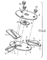
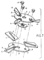
- the blade comprises a circular body composed of two parallel discs (6) and (9) between which are mounted radially knives (5).
- the knives are mounted in combination with axes (15) engaged in an oblong slot (3) in order, on the one hand, to be automatically retracted against a non-guilty hard object and, on the other hand, brought back in working position under the effect of centrifugal force.
- the knives which have two cutting edges (4) are rectangular and have two diagonally opposite angles (2) radiated to allow their total retraction.
- the knives (5) may have, according to a first characteristic, on their face (1), an oblong slot; placed so as to allow perfect articulation of the knife between the discs (6), either in the axis of a longitudinal line, or off-center with respect to this line, to the right or to the left, depending on the cutting angle that we want.
- the position of this light acting on the mass of inertia will tend to tilt the knife, either backwards relative to the axis of the disc, or forward.
- the hinge pins (15) of the knives (5) are engaged in an oblong slot (3), allowing instantaneous reversal of the knife without disassembly.
- the angle formed between the light and the side of the knife will vary depending on the desired cutting angle.
- the knives thus free on their axes of assembly, are automatically placed at the cutting angle provided under the effect of centrifugal force from the first turns of the blade.
- Their thickness of about 3 mm can vary depending on the work to be done. For example, knives designed in steel are subjected to a treatment giving them optimum hardness while respecting a flexibility preserving them from breakage.
- the diagonal arrangement of the oblong lumen (3) displaces the inertia and maintains the cutting edge (4) of the knife still in axis with the center of the blade.
- the knives have a radius (2) on two diagonally opposite angles allowing total retraction between the discs and are rectangular, perfectly symmetrical with respect to the point of intersection of two diagonal lines, which allows the reversal without any imbalance of the blade, thus alternately offering one or the other of the two cutting edges (4) depending on wear, without any disassembly.
- the discs (6) and (9) have, in the center, a bore (8) cooperating with circular bearings (11) (14) of a spacer designated as a whole by (10).
- Three equidistant holes (7) are placed approximately 12 mm from the edge of the circumference of the discs (6) and (9) and can vary in their diameter or in their position depending on the diameter of said discs. These holes (7) receive the axis (15) which can be screwed or riveted and of a diameter (16) corresponding to the diameter of said holes (7), allowing the disks to be assembled, between which the knives are placed and , of the spacer (10) maintaining the spacing of the discs, to allow the knives to articulate freely.
- the spacer has two shoulders (11) and (14) corresponding to the thickness of the disc (less than two tenths) so that the clamping of the blade on the machine is more effective. It also includes a bore (12) corresponding to the diameter of the axis of the machine used.
- the knives according to the invention are retractable. When in contact with a hard object, they slide between the two discs (6) and (9) and disappear entirely, thus avoiding any risk of impact which could cause deterioration of the mechanical parts of the machine. After the retraction of the ribs, only the discs remain in contact with the obstacle and, as soon as it is removed, the centrifugal force returns the ribs to the working position.
- fins (21), in the form of half-helices are placed on the upper part of the disc, either using the same axis, or using a different axis whose location will be determined on the disc. These fins, thus placed, allow a raised portion (19) forming pale, to drive the mowed lawn to a recovery tank. Articulated in the same way as the ribs, the fins are retractable, in full, upon contact with a hard object or, in the event of jamming of the lawn. They can be installed on most compact blades existing on the market according to a specific working position.
Landscapes
- Life Sciences & Earth Sciences (AREA)
- Environmental Sciences (AREA)
- Harvester Elements (AREA)
Claims (9)
- Messer für tragbare Gebüschschneider und Rasenmäher, mit rechteckiger Form und zwei gegenüberliegenden Schneidkanten, sowie einem Längsschlitz (3) zur Zusammenwirkung mit der Achse des Messers; dadurch gekennzeichnet, daß es völlig symmetrisch geformt ist in bezug auf den Schnittpunkt von zwei Diagonallinien und daß der Längsschlitz (3) gemäß einem Winkel mit Bezug auf die Seite des Messers geneigt ist, der mit dem erwünschten Schneidwinkel auf der Vorderseite ändert, für ein sofortiges Wenden des Messers, damit abwechselnd die eine oder die andere der beiden Schneidkanten (4) wirksam sein kann, je nach dem Abnutzungsgrad ohne jede Zerlegung.
- Messer nach Anspruch 1, dadurch gekennzeichnet, daß es auf zwei diagonal gegenüberliegenden Ecken einen Radius (2) aufweist, zum völligen Zurückbewegen des Messers.
- Rotor für Maschinen insbesondere der tragbaren Gebüschschneider- und Rasenmäherbauart, mit zwei konzentrischen und parallelen Scheiben (6-9), welche über ein Zwischenstück (10) in Abstand voneinander gehalten werden, dadurch gekennzeichnet, daß die zwei Scheiben (6-9) durch Schäfte (15) zusammengefügt sind, welche sich durch den Längsschlitz (3) des Messers entsprechend einem der Ansprüche 1 oder 2 erstrecken.
- Rotor nach Anspruch 3, dadurch gekennzeichnet, daß der Schaft (15) geschraubt oder genietet sein kann zum Zusammenbauen der Scheiben (6-9) zwischen welchen die Messer (1) angeordnet sind, wobei ein Zwischenstück (10) die Beabstandung der Scheiben gewährleistet, damit die Messer frei beweglich sind.
- Rotor nach Anspruch 4, dadurch gekennzeichnet, daß das Zwischenstück zwei Schultern (11-14) aufweist, welche beidseitig des Zwischenstücks angeordnet sind und eine kleinere Dicke als die Dicke der Scheibe aufweisen, damit das Festklemmen des Rotors an der Maschine sicherer ist.
- Rotor nach einem der Ansprüche 4 oder 5, dadurch gekennzeichnet, daß das Zwischenstück (12) eine Bohrung aufweist, welche durch den Durchmesser der Maschinenwelle bestimmt ist.
- Rotor nach einem der Ansprüche 3 bis 6, dadurch gekennzeichnet, daß er Flügel (21) in Form von Blatthälften aufweist, die auf einer der Scheiben (6) angeordnet sind zum Forttreiben des geschnittenen Grases, wobei die Flügel mit einem aufwärts ragenden Teil (19) versehen sind, der als Flügelblatt dient.
- Rotor nach Anspruch 7, dadurch gekennzeichnet, daß die Flügel koaxial zu den Messern angeordnet sind oder auf einer Achse sitzen, welche auf der Fläche der Scheibe durch ein Loch (20) bestimmt ist.
- Rotor nach einem der Ansprüche 7 oder 8, dadurch gekennzeichnet, daß die Flügel zurückbeweglich sind beim Aufschlagen gegen einem harten, nicht schneidbaren Gegenstand.
Applications Claiming Priority (2)
| Application Number | Priority Date | Filing Date | Title |
|---|---|---|---|
| FR9215125A FR2699042B1 (fr) | 1992-12-10 | 1992-12-10 | Lame pour débroussailleuse portable et tondeuse à gazon. |
| FR9215125 | 1992-12-10 |
Publications (2)
| Publication Number | Publication Date |
|---|---|
| EP0603086A1 EP0603086A1 (de) | 1994-06-22 |
| EP0603086B1 true EP0603086B1 (de) | 1997-03-12 |
Family
ID=9436633
Family Applications (1)
| Application Number | Title | Priority Date | Filing Date |
|---|---|---|---|
| EP93420485A Expired - Lifetime EP0603086B1 (de) | 1992-12-10 | 1993-12-08 | Messer für Maschinen wie zum Beispiel tragbare Sichelmäher und Rasenmäher |
Country Status (4)
| Country | Link |
|---|---|
| EP (1) | EP0603086B1 (de) |
| AT (1) | ATE149785T1 (de) |
| DE (1) | DE69308780D1 (de) |
| FR (1) | FR2699042B1 (de) |
Cited By (1)
| Publication number | Priority date | Publication date | Assignee | Title |
|---|---|---|---|---|
| EP4000371B1 (de) * | 2020-11-13 | 2024-09-18 | Andreas Stihl AG & Co. KG | Klinge für ein mähwerk, für einen rasenmäher und/oder eine motorsense, mähwerk für einen rasenmäher und/oder eine motorsense und rasenmäher und/oder motorsense |
Families Citing this family (5)
| Publication number | Priority date | Publication date | Assignee | Title |
|---|---|---|---|---|
| FR2717037B1 (fr) * | 1994-03-11 | 1996-04-12 | Joseph Bruneau | Dispositif pour tondre, faucher, débroussailler ou tailler la végétation. |
| ITUD20080140A1 (it) * | 2008-06-19 | 2009-12-20 | Styl Te Mec S R L | Testa di taglio per un decespugliatore, tagliaerba o simile utensile o macchina da taglio |
| US20180103583A1 (en) | 2015-03-25 | 2018-04-19 | Husqvarna Ab | Improved impact resistance for a robotic working tool |
| CN107079719B (zh) * | 2017-06-22 | 2022-04-15 | 杭州师范大学钱江学院 | 折展式树木修剪装置 |
| CN115338696B (zh) * | 2021-05-13 | 2023-09-29 | 广东博智林机器人有限公司 | 刀具及打磨装置 |
Family Cites Families (5)
| Publication number | Priority date | Publication date | Assignee | Title |
|---|---|---|---|---|
| US3507104A (en) * | 1967-05-25 | 1970-04-21 | Sperry Rand Corp | Knife mounting |
| US3621642A (en) * | 1970-10-09 | 1971-11-23 | Harry A Leake Jr | Rotary cutter head assembly for lawn mowers |
| US3894385A (en) * | 1974-01-15 | 1975-07-15 | Jr Charles K Brown | Cutting head for rotary lawn mower |
| DE2448130A1 (de) * | 1974-10-09 | 1976-04-22 | Gerhard Dr Ing Maerz | Schneidwerk fuer sichel-rasenmaeher |
| DE3838427A1 (de) * | 1988-11-12 | 1990-05-17 | Alois Schneider | Maehklingen fuer rotationsmaeher fuer vierseitige verwendbarkeit |
-
1992
- 1992-12-10 FR FR9215125A patent/FR2699042B1/fr not_active Expired - Fee Related
-
1993
- 1993-12-08 EP EP93420485A patent/EP0603086B1/de not_active Expired - Lifetime
- 1993-12-08 DE DE69308780T patent/DE69308780D1/de not_active Expired - Lifetime
- 1993-12-08 AT AT93420485T patent/ATE149785T1/de active
Cited By (1)
| Publication number | Priority date | Publication date | Assignee | Title |
|---|---|---|---|---|
| EP4000371B1 (de) * | 2020-11-13 | 2024-09-18 | Andreas Stihl AG & Co. KG | Klinge für ein mähwerk, für einen rasenmäher und/oder eine motorsense, mähwerk für einen rasenmäher und/oder eine motorsense und rasenmäher und/oder motorsense |
Also Published As
| Publication number | Publication date |
|---|---|
| FR2699042A1 (fr) | 1994-06-17 |
| ATE149785T1 (de) | 1997-03-15 |
| DE69308780D1 (de) | 1997-04-17 |
| FR2699042B1 (fr) | 1995-02-10 |
| EP0603086A1 (de) | 1994-06-22 |
Similar Documents
| Publication | Publication Date | Title |
|---|---|---|
| EP0099314B1 (de) | Vorrichtung zum Verhindern von Erdanhäufung am Gehäuse eines Scheibenmähers | |
| EP0175629B1 (de) | Kreiselmäher | |
| EP0245186A1 (de) | Mähvorrichtung | |
| EP1125487B1 (de) | Mehrzweckmaschine zum Zwischenkultivieren für Baum- oder Strauchpflanzungen bzw. Wein- oder Obstgärten | |
| EP3142833A1 (de) | Clipper für nasen- und ohrenhaare | |
| EP0206965A1 (de) | Rotationsmäher | |
| FR2674096A1 (fr) | Appareil de coupe, en particulier pour graminacees. | |
| EP0603086A1 (de) | Messer für Maschinen wie zum Beispiel tragbare Sichelmäher und Rasenmäher | |
| FR2965144A1 (fr) | Tondeuse a gazon | |
| EP1903855B1 (de) | Vorrichtung zum beschneiden und zerkleinern von pflanzen | |
| FR3164346A3 (fr) | Disque de coupe, structure de broyage de l’herbe et tondeuse à gazon | |
| FR2835393A1 (fr) | Lame a effet mulcheur pour debroussailleuse portable | |
| FR2850239A1 (fr) | Tete de coupe pour debroussailleuse, coupe-bordures ou analogue | |
| EP2057892B1 (de) | Mähwerk mit gekrümmtem Rahmen | |
| FR2553965A1 (fr) | Faucheuse rotative | |
| FR2736504A1 (fr) | Lame de coupe pour debroussailleur rotatif a axe vertical | |
| EP1151651B1 (de) | Vegetation-Mähvorrichtung mit Schlegel-Häcksler und Schneideanordnung | |
| FR2923136A1 (fr) | Moyens d'entrainement de disques de lamier | |
| FR2658982A1 (fr) | Lame pour dispositif de coupe de vegetaux. | |
| EP3272210B1 (de) | Rotor für gerät zur gestrüppentfernung | |
| FR2730898A1 (fr) | Marteau perfectionne pour epareuse | |
| CH204774A (fr) | Outil pour fraise agricole rotative. | |
| FR3150411A3 (fr) | Organe de travail rotatif pour dispositif de preparation culinaire | |
| FR2483740A1 (fr) | Appareil de debroussaillage | |
| FR3142324A1 (fr) | Dispositif de lamier pour l’élagage et le broyage de végétaux |
Legal Events
| Date | Code | Title | Description |
|---|---|---|---|
| PUAI | Public reference made under article 153(3) epc to a published international application that has entered the european phase |
Free format text: ORIGINAL CODE: 0009012 |
|
| 17P | Request for examination filed |
Effective date: 19940302 |
|
| AK | Designated contracting states |
Kind code of ref document: A1 Designated state(s): AT BE CH DE DK ES GB GR IE IT LI LU MC NL PT SE |
|
| 17Q | First examination report despatched |
Effective date: 19950202 |
|
| GRAH | Despatch of communication of intention to grant a patent |
Free format text: ORIGINAL CODE: EPIDOS IGRA |
|
| GRAH | Despatch of communication of intention to grant a patent |
Free format text: ORIGINAL CODE: EPIDOS IGRA |
|
| GRAA | (expected) grant |
Free format text: ORIGINAL CODE: 0009210 |
|
| AK | Designated contracting states |
Kind code of ref document: B1 Designated state(s): AT BE CH DE DK ES GB GR IE IT LI LU MC NL PT SE |
|
| PG25 | Lapsed in a contracting state [announced via postgrant information from national office to epo] |
Ref country code: NL Free format text: LAPSE BECAUSE OF FAILURE TO SUBMIT A TRANSLATION OF THE DESCRIPTION OR TO PAY THE FEE WITHIN THE PRESCRIBED TIME-LIMIT Effective date: 19970312 Ref country code: IT Free format text: LAPSE BECAUSE OF FAILURE TO SUBMIT A TRANSLATION OF THE DESCRIPTION OR TO PAY THE FEE WITHIN THE PRESCRIBED TIME-LIMIT;WARNING: LAPSES OF ITALIAN PATENTS WITH EFFECTIVE DATE BEFORE 2007 MAY HAVE OCCURRED AT ANY TIME BEFORE 2007. THE CORRECT EFFECTIVE DATE MAY BE DIFFERENT FROM THE ONE RECORDED. Effective date: 19970312 Ref country code: GR Free format text: LAPSE BECAUSE OF FAILURE TO SUBMIT A TRANSLATION OF THE DESCRIPTION OR TO PAY THE FEE WITHIN THE PRESCRIBED TIME-LIMIT Effective date: 19970312 Ref country code: GB Effective date: 19970312 Ref country code: ES Free format text: THE PATENT HAS BEEN ANNULLED BY A DECISION OF A NATIONAL AUTHORITY Effective date: 19970312 Ref country code: DK Effective date: 19970312 Ref country code: AT Effective date: 19970312 |
|
| REF | Corresponds to: |
Ref document number: 149785 Country of ref document: AT Date of ref document: 19970315 Kind code of ref document: T |
|
| REG | Reference to a national code |
Ref country code: CH Ref legal event code: EP |
|
| REF | Corresponds to: |
Ref document number: 69308780 Country of ref document: DE Date of ref document: 19970417 |
|
| REG | Reference to a national code |
Ref country code: IE Ref legal event code: FG4D Free format text: 72680 |
|
| PG25 | Lapsed in a contracting state [announced via postgrant information from national office to epo] |
Ref country code: SE Effective date: 19970612 Ref country code: PT Effective date: 19970612 |
|
| PG25 | Lapsed in a contracting state [announced via postgrant information from national office to epo] |
Ref country code: DE Effective date: 19970613 |
|
| NLV1 | Nl: lapsed or annulled due to failure to fulfill the requirements of art. 29p and 29m of the patents act | ||
| GBV | Gb: ep patent (uk) treated as always having been void in accordance with gb section 77(7)/1977 [no translation filed] |
Effective date: 19970312 |
|
| PG25 | Lapsed in a contracting state [announced via postgrant information from national office to epo] |
Ref country code: LI Free format text: LAPSE BECAUSE OF NON-PAYMENT OF DUE FEES Effective date: 19971231 Ref country code: CH Free format text: LAPSE BECAUSE OF NON-PAYMENT OF DUE FEES Effective date: 19971231 |
|
| PLBE | No opposition filed within time limit |
Free format text: ORIGINAL CODE: 0009261 |
|
| STAA | Information on the status of an ep patent application or granted ep patent |
Free format text: STATUS: NO OPPOSITION FILED WITHIN TIME LIMIT |
|
| 26N | No opposition filed | ||
| PG25 | Lapsed in a contracting state [announced via postgrant information from national office to epo] |
Ref country code: IE Free format text: LAPSE BECAUSE OF NON-PAYMENT OF DUE FEES Effective date: 19980330 |
|
| REG | Reference to a national code |
Ref country code: IE Ref legal event code: FD4D Ref document number: 72680 Country of ref document: IE |
|
| REG | Reference to a national code |
Ref country code: CH Ref legal event code: PL |
|
| PGFP | Annual fee paid to national office [announced via postgrant information from national office to epo] |
Ref country code: MC Payment date: 20011120 Year of fee payment: 9 |
|
| PGFP | Annual fee paid to national office [announced via postgrant information from national office to epo] |
Ref country code: LU Payment date: 20011129 Year of fee payment: 9 |
|
| PGFP | Annual fee paid to national office [announced via postgrant information from national office to epo] |
Ref country code: BE Payment date: 20011220 Year of fee payment: 9 |
|
| PG25 | Lapsed in a contracting state [announced via postgrant information from national office to epo] |
Ref country code: LU Free format text: LAPSE BECAUSE OF NON-PAYMENT OF DUE FEES Effective date: 20021208 |
|
| PG25 | Lapsed in a contracting state [announced via postgrant information from national office to epo] |
Ref country code: BE Free format text: LAPSE BECAUSE OF NON-PAYMENT OF DUE FEES Effective date: 20021231 |
|
| BERE | Be: lapsed |
Owner name: *LAYS LOUIS Effective date: 20021231 |
|
| PG25 | Lapsed in a contracting state [announced via postgrant information from national office to epo] |
Ref country code: MC Free format text: LAPSE BECAUSE OF NON-PAYMENT OF DUE FEES Effective date: 20030701 |