EP0603111A2 - Auf Strahlung ansprechendes chirurgisches Instrument - Google Patents
Auf Strahlung ansprechendes chirurgisches Instrument Download PDFInfo
- Publication number
- EP0603111A2 EP0603111A2 EP93630101A EP93630101A EP0603111A2 EP 0603111 A2 EP0603111 A2 EP 0603111A2 EP 93630101 A EP93630101 A EP 93630101A EP 93630101 A EP93630101 A EP 93630101A EP 0603111 A2 EP0603111 A2 EP 0603111A2
- Authority
- EP
- European Patent Office
- Prior art keywords
- crystal
- finger
- detector
- output
- cable
- Prior art date
- Legal status (The legal status is an assumption and is not a legal conclusion. Google has not performed a legal analysis and makes no representation as to the accuracy of the status listed.)
- Granted
Links
Images


Classifications
-
- G—PHYSICS
- G01—MEASURING; TESTING
- G01T—MEASUREMENT OF NUCLEAR OR X-RADIATION
- G01T1/00—Measuring X-radiation, gamma radiation, corpuscular radiation, or cosmic radiation
- G01T1/16—Measuring radiation intensity
- G01T1/161—Applications in the field of nuclear medicine, e.g. in vivo counting
-
- A—HUMAN NECESSITIES
- A61—MEDICAL OR VETERINARY SCIENCE; HYGIENE
- A61B—DIAGNOSIS; SURGERY; IDENTIFICATION
- A61B17/00—Surgical instruments, devices or methods
-
- A—HUMAN NECESSITIES
- A61—MEDICAL OR VETERINARY SCIENCE; HYGIENE
- A61B—DIAGNOSIS; SURGERY; IDENTIFICATION
- A61B6/00—Apparatus or devices for radiation diagnosis; Apparatus or devices for radiation diagnosis combined with radiation therapy equipment
- A61B6/42—Arrangements for detecting radiation specially adapted for radiation diagnosis
- A61B6/4208—Arrangements for detecting radiation specially adapted for radiation diagnosis characterised by using a particular type of detector
- A61B6/4258—Arrangements for detecting radiation specially adapted for radiation diagnosis characterised by using a particular type of detector for detecting non x-ray radiation, e.g. gamma radiation
-
- A—HUMAN NECESSITIES
- A61—MEDICAL OR VETERINARY SCIENCE; HYGIENE
- A61B—DIAGNOSIS; SURGERY; IDENTIFICATION
- A61B17/00—Surgical instruments, devices or methods
- A61B2017/00017—Electrical control of surgical instruments
- A61B2017/00022—Sensing or detecting at the treatment site
- A61B2017/00079—Radioactivity
-
- A—HUMAN NECESSITIES
- A61—MEDICAL OR VETERINARY SCIENCE; HYGIENE
- A61B—DIAGNOSIS; SURGERY; IDENTIFICATION
- A61B17/00—Surgical instruments, devices or methods
- A61B2017/0042—Surgical instruments, devices or methods with special provisions for gripping
- A61B2017/00438—Surgical instruments, devices or methods with special provisions for gripping connectable to a finger
-
- A—HUMAN NECESSITIES
- A61—MEDICAL OR VETERINARY SCIENCE; HYGIENE
- A61B—DIAGNOSIS; SURGERY; IDENTIFICATION
- A61B90/00—Instruments, implements or accessories specially adapted for surgery or diagnosis and not covered by any of the groups A61B1/00 - A61B50/00, e.g. for luxation treatment or for protecting wound edges
- A61B90/36—Image-producing devices or illumination devices not otherwise provided for
- A61B90/361—Image-producing devices, e.g. surgical cameras
- A61B2090/3614—Image-producing devices, e.g. surgical cameras using optical fibre
Definitions
- one technique includes the scintillation scanning of patients injected with relatively high energy, e.g. 131I labeled antibodies.
- Such photoscanning or scintillation scanning provides scintigrams difficult to interpret or of little value for detection of small lesions because of blood pool background radioactivity.
- Computer subtraction of radioactive blood pool agents and the use of two labeled antibodies (one specific for the tumor and one non-specific) have been attempted to enhance imaging. Nevertheless, such techniques have been found to provide little, if any, useful information to the surgeon, especially over and above CAT scans, magnetic resonance imagings, and like traditional techniques.
- large tumor is readily located by the surgeon by visualization at the operating theater as well as through palpation, i.e.
- the faint radiation emanating from neoplastic tissue at occult sites becomes detectable, for example, in part because of the inherent application of the approximate inverse square law of radiation propagation.
- the procedure is known as the Radioimmunoguided SurgeryTM system (Radioimmunoguided Surgery being a trademark of Neoprobe Corporation, Columbus, Ohio) and is successful additionally because of a recognition that tumor detection should be delayed until the blood pool background of circulating radiolabeled antibody has had an opportunity to be cleared from the body.
- the photon emissions or radiation emitted by minor tumors compared to surrounding tissue becomes detectable in view of the proximity of the probe device to it.
- the '840 patent discloses the ability of the radiolabeled antibody to remain bound to or associated with neoplastic tissue for extended periods of time with the radio tag still bound thereto. Moreover, even though the accretion of radioactivity at the tumor site decreases over time, the blood pool background and surrounding tissue (relative to the tumor sites) decrease at a much greater rate so that the radioactive sites can be determined readily utilizing a hand held probe positioned in close proximity with the tissue under investigation.
- This instrumentation supporting the probe device which is held by the surgeon and maneuvered within the body cavity is retained within a battery-powered console located within the operating room. Because of the low levels of signal evoked at the crystal detector within the probe, that device itself carries a preamplification stage for the purpose of generating a signal output suitable for transmission by cable or the like to the adjacent console.
- the preamplification stage performs in conjunction with a cadmium telluride crystal detector, and this combination of components is called upon to perform at the temperatures of the human body while undergoing calibration at substantially cooler temperatures found, for example, in the operating room environment. This requirement has tended to reduce the energy level discrimination flexibility of the devices.
- the architecture of the hand-held probe particularly as it is concerned with the noise-free mounting of the cadmium telluride crystal, has been described, for example, in the noted U.S. Pat. No. 4,801,803, U.S. Pat. No. 4,893,013, by Denen, entitled “Detector and Localizer for Low Energy Radiation Emissions", issued January 9, 1990, and in U.S. Pat. No. 5,070,878, by Denen, entitled “Detector and Localizer for Low Energy Radiation Emissions", issued December 10, 1991.
- the probe so described has an overall length of about 15 cm; is tubular in cross section, and has a forward tip portion canted at an angle of about 30 to aid the surgeon in maneuvering it within the body cavity.
- the present invention is addressed to apparatus and instrumentation for locating sources of radiation emissions which exhibit improved detecting capability both from the aspect of crystal response and with respect to the accessing of radiation sources.
- Crystal response and corresponding instrument performance is enhanced through the utilization of a cadmiumzinc-telluride crystal detector.
- This improved detector performance is complemented with an improved preamplifier.
- the cadmium-zinc-telluride crystal detector exhibits an output stability improved over the temperature excursions typically encountered within an operating room environment.
- the improved preamplifier achieves gain stability under temperature variations as well as an operation exhibiting low noise characteristics.
- the mounting architecture thereof may be somewhat simplified as compared to previous instrumentation utilizing non-alloyed cadmium telluride crystals. This, in turn, permits the implementation of the crystals within probe devices having quite variant structuring, including diminutive sizes.
- the probe or instrument of the invention is configured with a finger mount which is slidably retained on a select finger of the surgeon, for example the second finger.
- the device may be moved forwardly upon that finger to an operative position where the detection components are at the underside of the finger.
- stability is imparted to the device by the abutment of adjacent fingers upon guideways formed along the sides of the probe.
- the probe configuration also permits easy maneuvering of the instrument to a stand-by orientation at the upper side of the mounting finger at a rearward location adjacent the surgeon's knuckles. This stand-by orientation permits flexure of the hand for palpation procedures and the like while holding the probe at a convenient location where it readily is transferred back to an operational orientation.
- the finger mount carries a first preamplification stage including a charge accumulation network and an amplification stage which, in turn, is configured for conveying crystal derived signals over a relatively short length of cable.
- That cable of restricted length extends, for example, to a circuit housing attached to the surgeon's arm in the vicinity of the shoulder.
- additional amplification stages are installed for effecting signal transmission over somewhat lengthy shielded cable to a control console.
- these remotely located amplification stages are within a somewhat stable temperature environment away from heat exchange with the warmer surgeon's hand and patient's body.
- a sodium iodide crystal is employed in conjunction with a relatively short length of fiber optic transmission cable.
- This cable extends, as before, to a small housing mountable upon the surgeon's arm in the vicinity of the shoulder.
- the housing now contains a small photo-multiplier tube for conversion of scintillation-based data signals as received from the fiber optic bundle to electrical transmit signals. Isolation of the photo-multiplier tube is initially desirable for this embodiment inasmuch as such devices require relativley higher voltages which would not be desirable within instrumentation positioned closely adjacent a patient or within that patient's body cavity.
- locator includes a substance which preferentially concentrates at tumor sites by binding with a marker (the cancer cell or product of the cancer, for example) produced by or associated with neoplastic tissue or neoplasms.
- Appropriate locators today primarily include antibodies (whole and monoclonal), antibody fragments, chimeric versions of whole antibodies and antibody fragments, and humanized versions thereof. It should be appreciated, however, that single chain antibodies (SCAs such as disclosed in U.S. Pat. No. 4,946,778) and like substances have been developed and they primarily prove efficacious.
- Biochemistry and genetic engineering may yet produce substances which mimic the function of antibodies in selectively concentrating at sites of neoplastic tissue, though such substances may not be subsumed within the traditional definition of "antibody”.
- "Locator” is a term chosen to include present-day antibodies and equivalents thereof, as well as those substances yet to be determined which mimic antibodies in the method of the RIGS system.
- RIGS radioimmuno-guided surgical techniques
- a probe design which is configured to be carried and supported by a finger of the surgeon and which in the course of difficult accessing procedure may be moved between active detecting and stand-by positions, the latter positions permitting essentially full hand maneuverability at the site of tissue investigation.
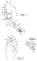
- a probe assembly according to the invention is represented generally at 10 as it is carried by a surgeon represented schematically at 12.
- the probe or probe component of the assembly 10 is shown at 16 being slidably mounted on the second finger 18 of the hand 20 of surgeon 12.
- Probe component 16 is represented as being in an active detection position such that it is mounted over the portion of finger 18 corresponding with one phalanx bone (connected to the tip phalanx) although location beneath a glove has been contemplated. It may, of course, be used on a different finger at the surgeon's discretion. In general, the probe 18 will be positioned over the sugical glove of the surgeon 12.
- the transmission arrangement thus shown includes a preamplification stage (not shown) which is mounted within the probe 16 itself and which is designed to provide an amplification of its detector output suited particularly for transmission along the length of cable 22 to a second preamplification circuit retained within circuit housing 30.
- the latter, second preamplification stage derives a transmit output of appropriate characteristic for transmission over the relatively lengthier cable 34. This arrangement enhances the capability for structuring the necessary small or diminutive probe component 16.
- Fig. 1 the "back" side of probe 16, which is an elastomeric strap, is seen. Looking to Fig. 2, the opposite side of this probe component 16 is revealed. Shown in Fig. 2 as being mounted at or near the tip of the underside of finger. 18, i.e. adjacent or over the terminal phalanx bone, the length of probe 16 along finger 18 is about 2 cm. This short length permits retention of the device while allowing finger flexure. Shown in phantom in the figure is a cavity 36 which serves as a seat within which a crystal detector is mounted and an adjacent rectangular enclosure or cavity 38 within which the noted initial pre-amplification stage may be retained. With this configuration, it is evident that the surgeon 12 is capable of maneuvering the probe at regions of the human anatomy otherwise quite difficult to access.
- Such position may, for example, move the device 16 to a location over the upper side of the third phalanx adjacent the palm as shown in Fig. 3.
- the active side of the probe 16 as seen in Fig. 2 is rotated to the top of the hand 20, as well as moved backwardly toward the palm or knuckles for flexure and unhindered use of hand 20.
- Probe 16 is shown in perspective.
- Probe 16 may be formed, for example, from aluminum or plastic, and is configured having a finger mount represented generally at 50 which includes a support region 52 and an oppositely-disposed concave mount portion 54.
- the support region 52 is seen to include a detector mount portion 56 and a pre-amplifier containment portion 58.
- detector mount portion 56 there is formed the earlier-noted crystal receiving cavity 36 and in adjacency thereto within the pre-amplifier containment portion 58 there is located the earlier-noted pre-amplifier containment cavity 38.
- Fig. 4 reveals that the outward surface of the concave mount portion 54 is configured in concave fashion to develop the above-discussed elongate guideways 62 and 64 extending along the lengthwise extent of finger mount 50. These guideways 62 and 64 aid in maintaining and changing the orientation of the probe 16 through their abutting contact with adjacent fingers of the surgeon's hand.
- the internal region of the concave mount portion 54 is configured substantially as a half cylindrical surface 63 of radius selected for nesting against the surgeon's mounting finger as described at 18 in Figs. 1-3. This surface 63 extends to two oppositely disposed strap connector portions 66 and 68. Looking additionally to Fig. 6, the strap connector portion 68 is seen to be formed as an elongate slot .
- Strap connector portion 66 is identically fashioned. These connector portions 66 and 68 serve to provide for the attachment of an elastomeric web-like strap 70 which functions to retain the finger mount 50 against the surgeon's hand and exhibits sufficient flexure or elasticity so as to permit the movement of the probe 16 about the finger, for example, in the orientations represented in Figs. 1-3.
- the support region 52 is seen to additionally support a cap or cover 72.
- This cover 72 is configured of a material and is dimensioned so as to seal the cavities 36 and 38 while permitting the ingress or passage of radiation into the detector mounted within detector cavity 36.
- the cover 72 may be formed of aluminum having a thickness, for example, of about 0.01 inch (0.25 mm).
- Figs. 4 and 6 show that the cover 72 is fashioned having a downwardly disposed and integrally formed flange or skirt 74 which nests over the support region 52 of finger mount 50.
- attachment between the cover 72 and support region 52 may be provided, for example, with an epoxy cement.
- stage 80 preferably is formed including a printed circuit board 82 which serves, in turn, to support surface mounted components, certain of which are represented at 84. Typically, the board 82 will function to mount those components on each of its oppositely disposed surfaces.
- Accessing the first preamplification stage 80 is the earlier-noted cable 22, the portion thereof immediately adjacent support region 52 being buttressed by a strain relief 86 formed, for example, of a soft rubber coating. Cable 22 is seen to extend through an aperture in the support region 52 for appropriate solder connections with circuit board 82.
- insulative silicon rubber compound represented at 88.
- Compound 88 is, for example, heat-stable silicone rubber sold under the trademark "SILASTIC".
- the latter product is an electrically insulative elastomeric adhesive which functions to retain its elastic properties over a broad range of environmental temperatures.
- the material is generally referred to as silicone rubber which is an elastomer in which the C linkages of a polymerized hydrocarbon are replaced by Si-O linkages.
- Electrical communication between the first preamplifier stage 80 and the detector components of probe 16 is provided through a channel or slot 90 extending between chambers 38 and 36.
- a small lead assemblage is shown at 92 extending through slot 90. Looking to Figs.
- the assemblage providing for the retention of a CdZnTe detector crystal 94 is revealed in general at 96.
- the outermost component of assemblage 96 is provided as a cup-shaped crystal retainer or outer shield 98 formed of lead of relatively thin dimension, for example, having a thickness of 0.25 mm.
- Cup 98 may be press fitted within cavity 36 and is formed having an aperture 100 (Fig. 7) through which the lead assembly 92 may pass.
- a layer of the above-described silicon rubber or "SILASTIC" compound Positioned over the lower surface or seat 102 (Fig. 6) of the cup 98 is a layer of the above-described silicon rubber or "SILASTIC" compound.
- Extending over the layer 104 are a plurality of strands 106 from a multi-strand wire within the cabling 92 functioning to provide an electrical bias for assertion against the inwardly disposed surface of crystal 94.
- the strands 106 of the biasing input to the assemblage are seen to be positioned over the upper surface of layer 104 such that they are electrically insulated from the seat 102 and so that they may contact a next adjacently-disposed disk shaped electrically conductive conformable cushion layer 108 having a lower disposed surface 110 positioned over the strands 106 and upon the forwardly facing surface of insulative elastomeric layer 104.
- the adhesive attachment between these components serves to avoid microphonically induced noise at the crystal 94.
- the electrically conductive cushion layer 108 is provided as a non-woven Teflon cloth which is carbon-filled to the extent rendering it an effective conductor of electricity.
- the material is a carbon-containing stretched, highly crystalline, unsintered polytetrafluoroethylene marketed under the trademark "GORETEX". To avoid contamination, it is desirable that the cushion layer 108 be as pure as possible through appropriate wash-type treatment or the like.
- layer 114 Positioned over the upwardly-disposed surface of crystal 94 is another electrically conductive deformable layer 114. Formed, for example, of material identical to that of layer 108, layer 114 serves to cushion the upper surface of crystal 94 against vibratory induced microphonic or the like effects as well as to provide electrical contact between its lower surface 116 and the upwardly-disposed surface of crystal 94.
- the electrically-conductive layer 114 functions to assert a ground by virtue of the freely-abutting contact of its upwardly disposed surface 118 with a ground lead 120 (Fig. 7) extending from the lead grouping of cable 22.
- a disk 122 Retaining the entire assemblage including layer 104, biasing strands 106, cushioning layer 108, crystal 94, cushioning layer 114, and ground lead 120 in proper mutually abutting association as well as in a slight compression is a disk 122.
- the disk 122 is structured so as to provide a press fit within the internal surfaces of cup 98.
- disk 122 may be secured adhesively utilizing the noted silicone rubber material.
- Fig. 5 reveals that the disk 122 retains the crystal supporting assemblage at a position below the cover 72 in a manner defining a gap 124. This gap 124 serves to isolate the crystal retaining assemblage from physical engagement with the cover 72.
- Gap 124 functions to provide an acoustic impedance to avoid the transmission of vibration from cover 72 which may be occasioned by the maneuvering of the probe 16 along tissue under investigation.
- Gap 124 is of relatively small height, for example about 0.5 mm, to assure that the forward surface of crystal 94 is as close as practical to the tissue under investigation. Such distancing of that forward surface with respect to the tissue under investigation is quite important in view of the low level of radiation involved and the noted inverse relationship of radiation propagation. In general, the user of the instrument 16 will witness a rapid fall-off of count response to radiation with the distancing of the forward surface of crystal 94 from such source.
- the diminutive size of the probe 16 is achieved both with the utilization of a dual stage preamplification arrangement as well as with the more simplified crystal mounting approach thus described.
- This latter mounting approach is, in part, made available through the selection of a CdTe material alloyed with zinc and generally represented by the expression: Cd 1-x Zn x Te.
- CdTe detecting crystals exhibit benefits such as operability at room temperature, high counting rates and small size.
- noise evoking temperature dependence which heretfore has been accommodated for through the elevation of lower window or threshold energy levels within control circuitry.
- Such an approach to accommodating these attributes of the non-alloyed crystals has, in the past, called for an operational trade-off representing loss of some radiation count data.
- cadmium telluride based instruments as employed in the operating theater are calibrated at a room or environmental temperature, for example, the temperature witnessed by the probe during calibration within an operating room may be somewhat below 15°C (59°F).
- the probe then is grasped by the surgeon, a maneuver which, in itself, will develop a higher temperature from the communication between the surgeon's hand and the probe.
- the probe is used within the body cavity where body temperature is about 39°C.
- the crystal component of the probe will more than likely reach a temperature of about 35°C and in some instances higher.
- the result from this temperature excursion heretofore utilizing CdTe crystals has been a generation of crystal dominant noise for which the instrumentation has been called upon to evoke an arbitrary lower window adjustment.
- a plot developed with a multi-channel analyzer utilizing a non-alloyed CdTe crystal in conjunction with a 129I check source is revealed.
- the curve represented in the figure was developed at room temperature (20°C) and in conjunction with a pre-amplifier as described in the above noted U.S. Patent No. 4,801,803 performing in conjunction with a console also as described therein.
- Count values as identified along the vertical scale of the figure were developed in conjunction with the relatively lengthy count interval of 20 seconds.
- the horizontal scale of the figure is representative of energy and is graduated in arbitrary channel designated units. In this regard, the channel identified at 800 will represent an energy of 29 kev, while that at the channel 200 designation will exhibit an energy valuation of about 7.5 kev.
- the figure reveals a principal count region 130 peaking at the noted 800 channel designation which is representative of the response of the crystal and preamplifier to impinging radiation from the 129I check source. Adjacent to the peak portion 130 is a relatively constricted region 132 leading from a skirt portion 134 of the peak region 130 to a rapidly rising noise response curve 136.
- a lower energy window is elected at the region 132 and at a location there-along which permits the gathering of all data possible from the desired skirt region 134.
- count data at the skirt region 134 is effectively discarded in the interest of noise avoidance.
- Fig. 9 The effect of temperature upon the noise characteristic of a CdTe crystal is illustrated in connection with Fig. 9.
- curves as at 138-143 were developed from data generated in connection with the taking of a sequence of count outputs from a CdTe crystal mounted as a probe for temperatures, respectively, of 10°, 15°, 20°, 25°, 30°, and 35°C.
- the horizontal scale of the chart is graduated in lower window settings for a console as described in the above-noted U.S. Patent No. 4,801,803.
- the preamplification stage utilized in compiling the data also is described in that reference.
- the dominant noise evolved in systems employing CdTe crystals is a characteristic of the crystal itself as opposed to being a characteristic of, for example, supporting circuitry such as a preamplification stage.
- the opposite condition obtains, the crystals exhibiting a stability over a broader temperature ranges to the extent that noise which may generated is dominantly generated from the supporting circuitry.
- Fig. 9 shows that at relatively cooler temperatures, i.e. 10°C as represented at curve 138, a broad selection of lower window settings as thresholds is available, noise development being relatively low.
- the lower window or energy threshold setting can be elected at a leftward region of the chart well away from the data containing skirt component as at 134 described in conjunction with Fig. 8.
- a noise count generally will be about 25 counts per 10 seconds as represented in Fig. 9 in conjunction with curve 138.
- this lower temperature is not realistic. Background noise will vary radically as temperature increases. For example, increasing the temperature by 5°C as represented at curve 139, results in an elevation of noise induced counts from about 100 to 200.
- elevation in operation temperature to 20°C as represented at curve 140 evokes an off-scale noise in the 400 to 500 counts per 10 second range.
- the lower window setting or lower threshold of evaluation must be moved towards the skirt component 134 as described in conjunction with Fig. 8.
- room temperature for example 25°C
- the system will look for a stable lower window setting, for example, as at position 84.
- the lower window setting must be moved substantially to the right representing a much higher lower threshold of energy and a level encroaching upon the valid count data otherwise available from the skirt 134.
- the preferred Cd 1-x Zn x Te detector crystals for the probe 16 as well as other probes exhibit very high stability with respect to noise generation when subjected to variations in temperature.
- these crystals are ideally suited for surgical procedures where calibration will occur at operating theater temperatures, i.e. about 15°C and the probe devices will absorb the heat of the surgeon's hand as well as the heat emanating from the body cavity of the patient undergoing surgery, a temperature excursion amounting, for example, to about 15 or 20°C.
- the proportioning of the Cd component and Zn component of the improved crystals may vary to provide an effective ratio selected to suit the particular requirements of the user.
- FIG. 10 an evaluation of a Cd.8Zn.2Te crystal employing a 129I check source and the preamplifier described later herein is charted as the output of a multi-channel analyzer.
- Vertical scale in the figure represents counts per 20 second interval, while the horizontal scale, as before, represents multi-channel analyzer channel designations which, in effect, represent energy.
- the radiation-based count data is derived at about 29 kev and is represented as the peak region 144.
- the relatively flat region 146 shown on the curve extending to the skirt region 148 is desirably of relatively large extent and considered to represent predominantly preamplifier noise, the latter noise being principally present at the spike region 150.
- the data represented by the chart at Fig. 10 was taken within an ice bath, i.e. with the alloyed crystal at 0°C.
- the same crystal evaluation then was undertaken at room temperature, i.e. at 22°C and the results plotted at Fig. 11.
- the data collection peak region 151 remains essentially the same as that observed at 144 in Fig. 10.
- the flat region representing consistent noise at 152 remains substantially the same as that described at 146 in Fig. 10 and that the noise spike excursion 154 remains essentially the same as that shown at 150 in Fig. 10.
- the alloyed crystal is seen to perform with a stability over a substantial alteration of temperature.
- the flat, consistent noise regions as at 152 and 146 in Figs. 11 and 10 also represent an improvement in preamplifier performance, for example, over the performance represented at Fig. 8.
- Figs. 12A and 12B a block diagrammatic representation of the signal treatment and control circuitry employed with the probe assembly 10 is revealed.
- that crystal which is being employed for example crystal 94
- Fig. 12A that crystal which is being employed, for example crystal 94
- Fig. 12A that crystal which is being employed, for example crystal 94
- FIG. 12A that crystal which is being employed, for example crystal 94
- FIG. 12A that crystal which is being employed, for example crystal 94
- Bias filter 160 is part of the earlier-described first or initial preamplification stage 80 herein identified in Fig. 12A by a dashed boundary with the same numeration.
- the input to the filter 160 is derived ultimately from cable 34 (Fig. 1) and is represented in Fig.
- Line 158 corresponds with the multi-strand line 106 described in connection with Fig. 7 and functions to supply an appropriate bias, for example, 80 v to the rearward surface of crystal 94. This bias emanates from a power supply shown at block 162 in Fig. 11B and represented at the labeled line 163.
- Line 158 from crystal 94 is shown extending to an integrator stage 164 of the first amplifier stage 80.
- the integrated valuation of a detected radiation disturbance or charge characterized signal then is shown directed as represented by line 165a to a driver-amplification network shown at block 166.
- Line 165 additionally is part of the cable or wiring 22 as it extends along the arm 24 of surgeon 12 as discussed in conjunction with Fig. 1.
- Line 165a extends to a second preamplification stage described as located within a housing 30 attached, in turn, to the shoulder region 28 of the arm of the surgeon 12.
- Cable 22 also may carry ground and +12v supply as shown, respectively, at lines 165b and 165c.
- the noted 12v power supply as represented at line 165c is derived for the driver amplifier stage 166 from the power supply 162 (Fig.
- Ground to the instrument 167 also is developed from the power supply at block 162 as represented at line 172 in Fig. 12A and which is seen extending to cable 34 and via line 173 to the driver-amplification stage 166.
- the output of the driver amplification stage 166 is represented at line 174 extending through the cable 34 and then is represented as line 175 to the input of a normalizing amplifier depicted at block 176.
- the network represented by block 176 functions to amplify or attenuate, i.e. scale the noise characteristic of any given instrument as at 16 and normalize the value thereof or render it consistent for later comparison stages.
- the 27 kev energy level gamma ray generated pulses in a system employing 125I will be about five times higher than noise levels.
- Normalizing amplifier network 176 will establish those noise levels at some predetermined level, for example 200 millivolts, and the resultant proportional valid gamma related pulses will become about 1v high for purposes of ensuing comparison functions. It may be observed that the amplifier network at block 176 is controlled from a digital-to-analog converter network represented at block 177 via line 178. Network 177, in turn, is controlled from line 179 extending, as shown in Fig. 12B, to block 180 representing a microcomputer network. The normalized output developed from network 176 is presented along lines 181 and 182 to a noise average circuit as represented at block 183.
- This network 183 determines an averager amplitude value for the noise of a given system with a given instrument 16 and provides a corresponding signal as represented at line 184 (noise amp) which is employed as above described as information used by the microcomputer 180.
- This information in addition to being employed with the normalizing amplifier network represented at block 176, may be used to develop a low window valuation for the comparison function.
- Line 182 also extends via line 186 to a pulse acquire network represented at block 188.
- This network functions, when activated, by the microcomputer represented at block 180, to acquire the value of the highest pulse amplitude witnessed at line 186. Periodically, this information then is transmitted to the microcomputer at block 180 as represented by line 190. Representing a form of peak detector, the network is sometimes referred to as a "snapshot circuit".
- a buffer amplifier which will provide at line 196 an output representing received pulses which may be made available to the system, for example, at a console (not shown).
- Line 181 extends, as shown in Fig. 12B, at line 198, to one input of an upper window comparator represented at block 200 and a lower window comparator illustrated at block 202.
- the threshold level for comparative purposes employed by the network at block 202 is shown asserted from line 204 and, preferably, is developed by the logic of microcomputer network 180 at a level selected above the noise amplitude signals generated from line 184.
- manual setting of such windows can be carried out and such setting in either event is in reliance upon the discourse presented hereinabove, for example, in connection with Figs. 8 through 11.
- the upper window of acceptance for valid radiation interaction is established from a corresponding line 206.
- This threshold setting may be made from the information taken from pulse acquire network 188.
- the upper window and lower window threshold selections are made under the control of the microcomputer network at block 180 which controls the digital-to-analog network shown at block 177. It is the characteristic of such networks as at block 177 to provide an output which is comprised, for example, of 256 steps of varying amplitude. The percentage of incrementation from step to step will vary somewhat over a range of voltage values provided. Accordingly, the outputs from this conversion network at block 177, as shown at lines 208 and 210 are directed to squarer network shown, respectively, at blocks 212 and 214. These networks function to square the current outputs at lines 208 and 210 and thus achieve a uniform percentage incrementation of the threshold defining outputs at lines 204 and 206.
- the outputs of the comparator networks shown at blocks 200 and 202 represent candidate pulses which may be above or below the given thresholds and are identified as being presented as "UW PULSE” and "LW PULSE” along respective lines 216 and 218. These lines are shown directed to a real time pulse discriminator network represented at block 220 which carries out Boolean logic to determine the presence or absence of valid pulses. Valid pulses are introduced to the microcomputer network 180 as represented by line 122.
- the microcomputer network represented at block 180 performs under a number of operational modes to provide both audio and visual outputs to aid the surgeon in locating and differentiating tumorous tissue.
- a volume control function may be asserted with amplitude variations controlled from a solid-state form of potentiometer represented at line 228 and block 230.
- Control to potentiometer 230 is represented at line 229.
- a "siren" type of frequency variation may be asserted as represented at line 232 to an audio amplification circuit represented at block 234 for driving a speaker as represented at 236 and line 238.
- the frequency output from speaker 236 increases as the instrument 16 is moved closer to the situs of concentrated radiation. of course, conventional clicks and beeps can be provided at the option of the operator.
- the microcomputer network 180 as represented by bus-defining arrow 240 and block 242 also addresses an input-output network which, as represented at bus arrow 244, functions to provide a pulse count output of varying types as well as outputs representing volume levels, pulse height, noise levels, and battery status. These outputs are provided in visual format at a visual display represented at block 245.
- the input-output function represented at block 242 provides appropriate scanning of switches or the like which may be employed with the control and are represented by block 241 and bus input arrow 243.
- the microcomputer network at block 180 functions to control a light emitting diode drive network represented by block 246 from line 248.
- the drive network represented at block 246 is shown providing an input as represented by line 250, to a light emitting diode (LED) display as represented by block 251.
- a serial output port of conventional variety also may be provided with the system, such ports being represented at block 252 being addressed from the microcomputer represented at block 80 from line 254 and having output and input components represented by arrow 256.
- a real time clock-calendar component having a non-volatile memory also may be provided in conjunction with the functions of the microcomputer network 180 as represented by block 258 and bus-arrow 260. Further, the microcomputer may be employed to monitor the performance of the power supply represented at block 162.
- the power supply also provides a +5v source for the logic level components of the circuit as represented by line 268; a -5v source at line 270, as well as a -9 source at line 272 for purposes of display drive, and finally, a 2.5v reference as represented at line 274 to provide reference input for the preamplification analog circuitry.
- the microcomputer network as represented at block 180 also provides an input to the digital-to-analog conversion network represented at block 177 which corresponds with the instantaneous pulse rate and this information is conveyed to a pulse rate amplifier network represented at block 276 via line 278.
- the resultant output, as represented at line 280, may be provided, for example, at a convenient location upon a console.
- This circuit represented at block 276 also may be employed to generate a calibrating pulse for testing the downstream components of the system.
- the microcomputer represented at block 180 applies a predetermined pulse level through the digital-to-analog conversion network at block 177 for presentation to the amplifier network represented at block 276.
- the resultant output at line 282 is selectively switched, as represented by block 284, to define pulse width from the microcomputer input at line 286 to generate the calibrating pulse at line 288.
- the diminutive, finger-ring-like structure of the probe 16 is achievable on a practical basis initially through the employment of a preamplification system which incorporates first and second stages. These stages are interconnected along the surgeon's arm by the earlier-noted cable 22 and the first stage 80 is so designed as to provide an initial signal treatment and an output topology particularly dedicated to the driving of data along the limited length of that shielded cable.
- the practically assembled but small size of this first stage 80 additionally is achieved through the utilization of, for example, surface mounted components. While the entire structure including the first and second stages may be formed together in a unitary fashion, for probe applications such as the present requiring a splitting of these stages, the printed circuit may be made so as to be severable at an appropriate location.
- the first stage is represented at Fig. 13A and the second stage is shown as such a continuation for the entire circuit in Fig. 13B. A parting line between these components of the circuit is conjunctional with the associational labeling between the two drawings.
- the crystal 94 reappears with the same numeration.
- the upward facing surface of crystal 94 is coupled to ground as represented by line 157 which reappears from Fig. 12A.
- bias is asserted to the rearward face of crystal 94 from line 158, again reappearing from Fig. 12A.
- An 80v bias voltage is applied to crystal 94 through the earlier-noted bias filter 160.
- the voltage is seen applied from line 161 to a decoupling network including resistor R1 and capacitor C1. This network reduces noise which might otherwise be injected from the power supply line 161. From the network incorporating capacitor C1 and resistor R1, the bias voltage is supplied through a very large value resistor R2 to lines 158 and 159.
- resistor R2 In general, the larger the resistance value of resistor R2, the smaller the amount of noise which may be contributed by that component. A small amount of current will flow through resistor R2 and its function is to maintain an appropriate bias at the crystal 94. That bias will approach the bais voltage applied from line 161. In this regard, the resistance of crystal 94 generally will be quite large.
- Line 158 is seen to extend to a blocking capacitor C2 functioning to block the bias voltage at the crystal 94 from the inputs of subsequent integrating or amplification stages. Accordingly, the opposite side of capacitor C2 is seen coupled via line 290 which is coupled, respectively, via lines 292 and 294 to a network including a charge accumulator capacitor C3 and a bleed resistor R3.
- Capacitor C3 receives the charge which is liberated by the crystal 94 in the event of a gamma strike. This voltage is witnessed, for example at node A, while the voltage at node B will have an approximately 0 value. Resistor R3 slowly bleeds the charge at capacitor C3 and, thus, has a relatively high resistance value, for example, about 200 megaohms. Such bleeding activity avoids saturation of the system.
- the first preamplifier stage generally is referred to as an integrator as described earlier in conjunction with block 164. That block numeration appears in general in conjunction with such integrating components of the instant first stage. Line 290 also is seen to extend to the gate of a junction field effect transistor (JFET) Q1.
- JFET junction field effect transistor
- Transistor Q1 in combination with PNP transistor Q2, and NPN transistor Q3 participates in this charge accumulation at capacitor C3 of the integrator categorized stage 164.
- +12v from earlier-described line 165c is provided to the stage 164 from a line designated with the same numeration through resistor R24 to a line 296.
- ground is asserted from along line 165b as earlier described which is indicated to extend to a line 298.
- the output of the first preamplification stage 80 is seen, as before, at line 164a.
- Line 296 extends to a connection with a resistor R5 to line 300 which is coupled between the drain terminal of transistor Q1 and the emitter of transistor Q2.
- Line 296 also extends through resistor R4 to a network 302 including capacitor C4 and Zener diode D1 which are coupled to the source terminal of transistor Q1 via line 304.
- Network 302 functions to bias the source terminal of transistor Q1 to approximately 3v.
- the collector of transistor Q2 is coupled to line 306 which extends to node A at line 292.
- Line 306 is seen to continue as line 308 to the collector of transistor Q3 and the emitter thereof at line 310 extends through resistor R8 to ground line 298.
- the bases of transistors Q2 and Q3 are associated with a divider network within line 312 extending between lines 296 and 298, and incorporating resistors R6-R9.
- the base of transistor Q2 is coupled via line 314 to line 312 intermediate resistors R6 and R7
- the base of transistor Q3 is coupled via line 316 to line 312 intermediate resistors R7 and R9.
- a constant voltage is applied at the base of transistor Q2 via line 314.
- Capacitor C5 carries out a noise reduction function at that base.
- the junction between resistors R7 and R9 provide a bias voltage to the base of transistor Q3 via line 316.
- Capacitor C6 within line 318 is seen coupled from line 312 at line 316 to ground line 298 and functions to by-pass a.c. perturbations at the base of transistor Q3 to ground.
- transistors Q1 and Q2 operate as a current mirror while transistor Q3 performs as a current source.
- the output of the integrator function is directed via earlier-described line 292 to the base of NPN transistor Q5.
- Transistor Q5 in conjunction with PNP transistor Q4 constitute a non-inverting voltage amplifier with a gain of about 3.
- the amplifier is configured such that the collector of transistor Q5 is connected via line 320 to line 296 and incorporates a bias resistor R11.
- the emitter of transistor Q5 is coupled via line 322 to line 324 intermediate gain defining resistors R12 and R13. Line 324 is seen to extend between ground line 298 and the collector of transistor Q4.
- the latter component Q4 is configured such that its base is coupled to line 320 via line 326 and its emitter is connected to line 296 via line 328.
- a capacitor C9 is seen coupled to line 296.
- the gain of this amplification stage is established by the ratio of the sum of the resistance values of resistors R12 and R13 to the resistance value of resistor R13. This arrangement avoids having a gain dependent upon the functioning of the transistor devices themselves.
- a desirable property of the amplifier configuration of transistors Q4 and Q5 is that the input resistance at the base of transistor Q5 is very, very large. This is provided in order to avoid the loading of the output of the circuit.
- the output impedance or resistance i.e. the output resistance at the collector of transistor Q4 which is asserted at line 165a is rather low.
- the magnitude of this output resistance is on the order of 90 ohms, a level which permits the driving of the shielded cable described in connection with Fig. 1 which extends from the probe 16 to the second preamplification stage housing 30 and is represented as being incorporated within cable line 22.
- the output voltage swing at line 165a is between 5 and 10 millivolts.
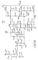
- the second preamplification stage is revealed.
- this stage will be incorporated within the amplification stage housing 30 affixed to the surgeon's shoulder.
- the entire preamplification unit represented within Figs. 13A and 13B can be employed as a continuous circuit without the noted splitting.
- the task of the second preamplification stage is to provide additional gain in view of the relatively low voltages asserted at line 165a and to achieve a form of reproduction of the waveform represented by the input signal to the system and somewhat reproduced in amplifier form at line 165a.
- Line 165a is seen directed to a network serving to carry out an approximate of differentiation which includes capacitor C7 and resistor R15 within line 330.
- Line 330 extends to line 332 and resistor R26 to +12v supply at line 165c.
- a diode connected transistor Q10 is coupled within line 330 between resistor R15 and line 165b or ground.
- NPN device Q10 functions to retain the operating point bias at the base of NPN transistor Q7 which is seen coupled to line 330 via line 334.
- the peak output of the approximate differentiation evoked in conjunction with resistor R15 and capacitor C7 is considered to represent the magnitude of the charge evoked at the crystal 94 and as presented at line 334 to the base of NPN transistor Q7.
- Transistor Q7 and PNP transistor Q6 form an amplification stage quite similar to that described in conjunction with transistors Q4 and Q5 in Fig. 13B.
- the input resistance at the base of transistor Q7 is rather large and the gain of the amplification stage including transistors Q6 and Q7 is controllable and selected as about 19 or 20.
- the stage is configured such that the collector of transistor Q7 is coupled via line 336 through bias resistor R16 to line 330 while the emitter thereof is coupled via line 338 to line 340 which, in turn, is connected between the collector of transistor Q6 and ground line 165b.
- Line 338 is positioned intermediate resistors R17 and R18 in line 340.
- the emitter of transistor Q6 is coupled via line 342 to line 330 and the output of the stage at the collector thereof is present at line 344.
- the gain of this amplification stage is very controllable and is determined by the ratio of the resistance values of resistors R17 and R18.
- the output impedance at the collector of transistor Q6 is rather low, again on the order of 90 ohms. This low output impedance permits a considerable flexibility with respect to the magnitude of the components within the topology to follow.
- the gain of the configuration of the amplification stage is quite stable, not being a function of the individual transistor devices.
- Output line 344 is seen to extend through resistor R10 which is associated with a capacitor C10 coupled within line 346 between line 344 and ground line 165b.
- the network including resistor R10 and capacitor C10 constitutes a low pass filter with the function of eliminating as much electrically generated noise as possible.
- Line 344 then is seen to extend to a coupling capacitor C8 which functions to couple the resulting voltage at the junction of resistor R10 and capacitor C10 in conjunction with resistor R20 to the input of a next amplification stage.
- That next amplification stage is comprised of NPN transistor Q9 and PNP transistor Q8.
- Bias voltage is supplied to the base of transistor Q9 in conjunction with resistors R19, R25, and diode connected transistor Q11 in the same fashion as the bias selected with respect to transistor Q7.
- resistors R19, R25, and transistor Q11 are coupled within line 348 between lines 330 and 165b.
- Resistor R20 is coupled to the base of transistor Q9 and thence via line 350 to line 348 at a location intermediate resistors R19 and R25. If there is a bias point variation at transistors Q8 and Q9, for example, as a function of temperature change, it is likely that the output of the stage would evoke a corresponding and objectionably large change.
- Transistor Q11 functions to offset that change in bias voltage to greatly reduce the temperature dependency of the amplification stage.
- utilization of transistors Q10 and Q11 in the circuit of Fig. 13B provides a substantial and important temperature stability for the circuit. The same form of stability is not implemented in connection with the circuit of Fig. 13A in view of the relatively low gain developed by that circuity. It may be observed additionally that with the split preamplifier approach, the longer gain stages of the amplifier are retained within a more stable temperature environment.
- the collector of NPN transistor Q9 is coupled via line 352 through bias resistor R21 to line 330, while the emitter thereof is coupled via line 354 to line 356 which, in turn, incorporates gain defining resistors R22 and R23 and extends between line 165b and the collector of PNP transistor Q8.
- the base of transistor Q8 is coupled via line 358 to line 352, while the emitter thereof is coupled to line 330 via line 360.
- the output of the final amplification stage is provided at the collector of transistor Q8 which is seen, in turn, coupled to earlier-described line 174 (Fig. 12A) which reappears in the instant figure.
- it is desired to set the biasing of transistors Q8 and Q9 such that the output at line 174 under queiscent conditions is just above 0 volts. This permits accommodation of energetic isotopes which may produce excursions of 8 or 10 volts.
- a sodium iodide-based finger mounted probe is represented generally at 370.
- Probe 370 exhibits the same appearance as the probe 16 represented in Fig.4 and, in particular, includes a support region 372 similar to that at 52 in the earlier embodiment beneath which is located a concave mount portion 374 (Fig. 15).
- Elongate concave guideways 376 and 378 are located on either side of the support region 372 and generally outwardly of the concave mount portion 374. These guideways, as before, aid the surgeon in maneuvering the probe 370 about the finger when utilizing the next adjacent fingers.
- elongate slots Just below these guideways at 376 and 378 are elongate slots, one of which is shown in Fig. 15 at 380 in Fig. 15. An identical slot is located beneath guideway 378 and these slots provide strap connector portions of the device for purposes of mounting an elastomeric web or strap 382 in the same fashion that strap 70 is connected to device 16.
- a detector mount portion 384 Within which a crystal retaining cavity 386 is formed.
- Fig. 14 reveals a bore through which a fiber optic bundle 390 extends in communication with the cavity 386.
- the base components of device 370 including the support region 372, concave mount portion 374, and the guideways 376 and 378 may be formed integrally of an opaque plastic.
- a plastic cover 392 having a skirt portion 394 (Fig. 15) which nests against a ridge 396 (Fig. 14) formed within the support region 372.
- the cover may, for example, be adhesively attached to the unit 370.
- a sodium iodide crystal is shown in Fig. 15 at 398 being positioned within a thin lead cup 400 and retained in position within that cup 400 by a silicon rubber adhesive represented at 402.
- the crystal 398 is silvered on all sides except at its light commuting contact with bundle 390.
- an optical grease may be employed to improve the transmission of light from the crystal 398 to the bunde 390.
- Bundle 390 extends to a photomultiplier device (not shown) which is retained within a shoulder mounted housing such as that shown at 30 in Fig. 1.
- the output signals from the photomultiplier device extend via cable as at 34 to a central console which may be configured as described in conjunction with Figs. 12A and 12B.
- Exemplary of photomultiplier devices which may be employed with the instant probe embodiment is a Model R-1635-02 photomultiplier tube marketed by Hamamatsu Corp., Bridgewater, N.J. In general, that device has overall dimensions of about 1 cm x 5 cm. Advantage further accrues with the remote location of the photo-multiplier. In this regard, such devices perform at relatively high voltage, i.e. 1000 v. By so remotely locating them, they are desirably positioned away from the patient.
Landscapes
- Health & Medical Sciences (AREA)
- Life Sciences & Earth Sciences (AREA)
- Engineering & Computer Science (AREA)
- Medical Informatics (AREA)
- Surgery (AREA)
- General Health & Medical Sciences (AREA)
- Nuclear Medicine, Radiotherapy & Molecular Imaging (AREA)
- Biomedical Technology (AREA)
- Molecular Biology (AREA)
- Physics & Mathematics (AREA)
- Veterinary Medicine (AREA)
- Animal Behavior & Ethology (AREA)
- Heart & Thoracic Surgery (AREA)
- Public Health (AREA)
- High Energy & Nuclear Physics (AREA)
- Optics & Photonics (AREA)
- Pathology (AREA)
- Spectroscopy & Molecular Physics (AREA)
- Biophysics (AREA)
- General Physics & Mathematics (AREA)
- Radiology & Medical Imaging (AREA)
- Measurement Of Radiation (AREA)
- Nuclear Medicine (AREA)
- Materials For Medical Uses (AREA)
- Radiation-Therapy Devices (AREA)
- Amplifiers (AREA)
- Microwave Amplifiers (AREA)
Applications Claiming Priority (2)
| Application Number | Priority Date | Filing Date | Title |
|---|---|---|---|
| US992622 | 1992-12-18 | ||
| US07/992,622 US5441050A (en) | 1992-12-18 | 1992-12-18 | Radiation responsive surgical instrument |
Publications (3)
| Publication Number | Publication Date |
|---|---|
| EP0603111A2 true EP0603111A2 (de) | 1994-06-22 |
| EP0603111A3 EP0603111A3 (de) | 1995-02-01 |
| EP0603111B1 EP0603111B1 (de) | 1999-06-09 |
Family
ID=25538549
Family Applications (1)
| Application Number | Title | Priority Date | Filing Date |
|---|---|---|---|
| EP93630101A Expired - Lifetime EP0603111B1 (de) | 1992-12-18 | 1993-12-09 | Auf Strahlung ansprechendes chirurgisches Instrument |
Country Status (11)
| Country | Link |
|---|---|
| US (1) | US5441050A (de) |
| EP (1) | EP0603111B1 (de) |
| JP (1) | JP2816643B2 (de) |
| KR (1) | KR0181304B1 (de) |
| AT (1) | ATE180955T1 (de) |
| AU (2) | AU671318B2 (de) |
| CA (1) | CA2110858C (de) |
| DE (1) | DE69325248T2 (de) |
| ES (1) | ES2133374T3 (de) |
| IL (1) | IL107921A (de) |
| MX (1) | MX9400055A (de) |
Cited By (3)
| Publication number | Priority date | Publication date | Assignee | Title |
|---|---|---|---|---|
| US6331703B1 (en) | 1999-03-12 | 2001-12-18 | Ethicon Endo-Surgery, Inc. | Guidance method for radiation detection |
| WO2003016948A1 (en) * | 2001-08-17 | 2003-02-27 | The Secretary Of State For Defence | A non-slip extremity dosimeter |
| EP0822405A3 (de) * | 1996-07-30 | 2004-07-07 | Bayer Corporation | Elektronisches System für Blutanalysegerät |
Families Citing this family (144)
| Publication number | Priority date | Publication date | Assignee | Title |
|---|---|---|---|---|
| US7820798B2 (en) * | 1994-11-07 | 2010-10-26 | Human Genome Sciences, Inc. | Tumor necrosis factor-gamma |
| US7597886B2 (en) * | 1994-11-07 | 2009-10-06 | Human Genome Sciences, Inc. | Tumor necrosis factor-gamma |
| US5732704A (en) * | 1995-10-13 | 1998-03-31 | Neoprobe Corporation | Radiation based method locating and differentiating sentinel nodes |
| US5857463A (en) * | 1995-10-13 | 1999-01-12 | Neoprobe Corporation | Remotely controlled apparatus and system for tracking and locating a source of photoemissions |
| US5967983A (en) * | 1995-10-31 | 1999-10-19 | Digirad Corporation | Apparatus for securing a medical imaging device to a body |
| US7888466B2 (en) | 1996-01-11 | 2011-02-15 | Human Genome Sciences, Inc. | Human G-protein chemokine receptor HSATU68 |
| US5682888A (en) * | 1996-06-13 | 1997-11-04 | Neoprobe Corporation | Apparatus and system for detecting and locating photon emissions with remote switch control |
| US5810806A (en) * | 1996-08-29 | 1998-09-22 | Ethicon Endo-Surgery | Methods and devices for collection of soft tissue |
| US6487439B1 (en) * | 1997-03-17 | 2002-11-26 | Victor N. Skladnev | Glove-mounted hybrid probe for tissue type recognition |
| US5928150A (en) * | 1997-10-04 | 1999-07-27 | Neoprobe Corporation | System for locating and detecting a source of photon emissions |
| US6077508A (en) * | 1998-03-23 | 2000-06-20 | American Diagnostica Inc. | Urokinase plasminogen activator receptor as a target for diagnosis of metastases |
| US6264949B1 (en) | 1998-09-29 | 2001-07-24 | Mount Sinai School Of Medicine Of New York University | Noninvasive agents for diagnosis and prognosis of the progression of fibrosis |
| US6218669B1 (en) | 1998-10-06 | 2001-04-17 | Neoprobe Corporation | Surgical probe apparatus |
| US6222193B1 (en) | 1998-10-06 | 2001-04-24 | Neoprobe Corporation | Radiation responsive surgical probe apparatus |
| US6191422B1 (en) | 1998-10-06 | 2001-02-20 | Neoprobe Corporation | Radiation probe with compound semiconductor crystal performing in a trapping-dependent operational mode |
| US6204505B1 (en) * | 1998-10-06 | 2001-03-20 | Neoprobe Corporation | Surgical probe apparatus and system |
| US6496717B2 (en) * | 1998-10-06 | 2002-12-17 | University Of South Florida | Radio guided seed localization of imaged lesions |
| US8114006B2 (en) * | 1998-10-06 | 2012-02-14 | University Of South Florida | Radio guided seed localization of imaged lesions |
| US6242741B1 (en) * | 1998-10-23 | 2001-06-05 | United States Surgical Corporation | Radiation detection apparatus |
| AU3501700A (en) | 1999-02-26 | 2000-09-14 | Human Genome Sciences, Inc. | Human endokine alpha and methods of use |
| US6236880B1 (en) | 1999-05-21 | 2001-05-22 | Raymond R. Raylman | Radiation-sensitive surgical probe with interchangeable tips |
| US6280398B1 (en) | 1999-10-18 | 2001-08-28 | Ethicon Endo-Surgery | Methods and devices for collection of soft tissue |
| AU2002219944B2 (en) | 2000-11-28 | 2008-02-21 | Medimmune, Llc | Methods of administering/dosing anti-RSV antibodies for prophylaxis and treatment |
| US6602488B1 (en) | 2000-03-03 | 2003-08-05 | Intramedical Imaging, Llc | Use of radiopharmaceuticals and intraoperative radiation probe for delivery of medicinal treatments |
| US6510336B1 (en) | 2000-03-03 | 2003-01-21 | Intra Medical Imaging, Llc | Methods and devices to expand applications of intraoperative radiation probes |
| US7373197B2 (en) * | 2000-03-03 | 2008-05-13 | Intramedical Imaging, Llc | Methods and devices to expand applications of intraoperative radiation probes |
| EP2213743A1 (de) | 2000-04-12 | 2010-08-04 | Human Genome Sciences, Inc. | Albuminfusionsproteine |
| EP2431054A3 (de) | 2000-06-15 | 2013-03-06 | Human Genome Sciences, Inc. | Menschlicher Tumornekrosefaktor Delta und Ypsilon |
| PT2281843T (pt) | 2000-06-16 | 2017-01-02 | Human Genome Sciences Inc | Anticorpos que se ligam imunoespecificamente a blys |
| WO2004042546A1 (en) | 2002-11-04 | 2004-05-21 | V-Target Technologies Ltd. | Apparatus and methods for imaging and attenuation correction |
| US8036731B2 (en) | 2001-01-22 | 2011-10-11 | Spectrum Dynamics Llc | Ingestible pill for diagnosing a gastrointestinal tract |
| US8909325B2 (en) | 2000-08-21 | 2014-12-09 | Biosensors International Group, Ltd. | Radioactive emission detector equipped with a position tracking system and utilization thereof with medical systems and in medical procedures |
| US8565860B2 (en) | 2000-08-21 | 2013-10-22 | Biosensors International Group, Ltd. | Radioactive emission detector equipped with a position tracking system |
| US8489176B1 (en) | 2000-08-21 | 2013-07-16 | Spectrum Dynamics Llc | Radioactive emission detector equipped with a position tracking system and utilization thereof with medical systems and in medical procedures |
| US7083784B2 (en) | 2000-12-12 | 2006-08-01 | Medimmune, Inc. | Molecules with extended half-lives, compositions and uses thereof |
| IL157007A0 (en) | 2001-01-22 | 2004-02-08 | Target Technologies Ltd V | Ingestible device |
| JP2004536579A (ja) | 2001-04-13 | 2004-12-09 | ヒューマン ジノーム サイエンシーズ, インコーポレイテッド | 血管内皮増殖因子2 |
| US7064189B2 (en) | 2001-05-25 | 2006-06-20 | Human Genome Sciences, Inc. | Antibodies that immunospecifically bind to trail receptors |
| US7795213B2 (en) * | 2001-12-13 | 2010-09-14 | Posco | Methods of contacting β amyloid protein with VEGF |
| AU2002364586A1 (en) | 2001-12-21 | 2003-07-30 | Delta Biotechnology Limited | Albumin fusion proteins |
| AU2003218456A1 (en) * | 2002-04-01 | 2003-10-20 | Human Genome Sciences, Inc. | Antibodies that specifically bind to gmad |
| WO2003086458A1 (en) | 2002-04-12 | 2003-10-23 | Medimmune, Inc. | Recombinant anti-interleukin-9 antibodies |
| AU2003274463B2 (en) | 2002-06-10 | 2009-10-29 | University Of Rochester | Gene differentially expressed in breast and bladder cancer and encoded polypeptides |
| DK1534335T4 (en) | 2002-08-14 | 2015-10-05 | Macrogenics Inc | FCGAMMARIIB-SPECIFIC ANTIBODIES AND PROCEDURES FOR USE THEREOF |
| WO2004035537A2 (en) | 2002-10-16 | 2004-04-29 | Euro-Celtique S.A. | Antibodies that bind cell-associated ca 125/o772p and methods of use thereof |
| US20040116807A1 (en) * | 2002-10-17 | 2004-06-17 | Roni Amrami | Blood vessels wall imaging catheter |
| JP2006518997A (ja) * | 2003-01-21 | 2006-08-24 | ブリストル−マイヤーズ スクイブ カンパニー | 新規アシルコエンザイムa:モノアシルグリセロールアシルトランスフェラーゼ−3(mgat3)をコードするポリヌクレオチドおよびその用途 |
| AU2004229501B2 (en) | 2003-04-11 | 2011-08-18 | Medimmune, Llc | Recombinant IL-9 antibodies and uses thereof |
| US20050239700A1 (en) * | 2003-10-14 | 2005-10-27 | Biogen Idec Inc. | Treatment of cancer using antibodies to LRRC15 |
| AU2004296184B2 (en) * | 2003-12-04 | 2010-12-16 | Vaccinex, Inc. | Methods of killing tumor cells by targeting internal antigens exposed on apoptotic tumor cells |
| US7371381B2 (en) * | 2003-12-12 | 2008-05-13 | Amgen Inc. | Anti-galanin antibodies and uses thereof |
| PL3718564T3 (pl) | 2003-12-23 | 2024-03-18 | Genentech, Inc. | Nowe przeciwciała anty-IL 13 i ich zastosowania |
| CN1981210A (zh) | 2004-01-13 | 2007-06-13 | 光谱动力学有限责任公司 | 多维图像重构 |
| US8571881B2 (en) | 2004-11-09 | 2013-10-29 | Spectrum Dynamics, Llc | Radiopharmaceutical dispensing, administration, and imaging |
| US9040016B2 (en) | 2004-01-13 | 2015-05-26 | Biosensors International Group, Ltd. | Diagnostic kit and methods for radioimaging myocardial perfusion |
| WO2007054935A2 (en) | 2005-11-09 | 2007-05-18 | Spectrum Dynamics Llc | Dynamic spect camera |
| US8586932B2 (en) | 2004-11-09 | 2013-11-19 | Spectrum Dynamics Llc | System and method for radioactive emission measurement |
| US7968851B2 (en) | 2004-01-13 | 2011-06-28 | Spectrum Dynamics Llc | Dynamic spect camera |
| US9470801B2 (en) | 2004-01-13 | 2016-10-18 | Spectrum Dynamics Llc | Gating with anatomically varying durations |
| US10964075B2 (en) | 2004-01-13 | 2021-03-30 | Spectrum Dynamics Llc | Gating with anatomically varying durations |
| HUE027902T2 (en) | 2004-02-09 | 2016-11-28 | Human Genome Sciences Inc Corp Service Company | Albumin fusion proteins |
| US20050203331A1 (en) * | 2004-03-09 | 2005-09-15 | Szapucki Matthew P. | Neurosurgical instrument with gamma ray detector |
| US7247855B2 (en) * | 2004-03-09 | 2007-07-24 | United States Of America As Represented By The Secretary Of The Army | Portable nuclear detector |
| EP1750676B1 (de) * | 2004-05-20 | 2014-07-23 | Biosensors International Group, Ltd. | Einnehmbare produktplattform für den kolon |
| US8280124B2 (en) | 2004-06-01 | 2012-10-02 | Spectrum Dynamics Llc | Methods of view selection for radioactive emission measurements |
| EP1778957A4 (de) | 2004-06-01 | 2015-12-23 | Biosensors Int Group Ltd | Optimierung der messung radioaktiver strahlung an besonderen körperstrukturen |
| US8615405B2 (en) | 2004-11-09 | 2013-12-24 | Biosensors International Group, Ltd. | Imaging system customization using data from radiopharmaceutical-associated data carrier |
| US8423125B2 (en) | 2004-11-09 | 2013-04-16 | Spectrum Dynamics Llc | Radioimaging |
| US9316743B2 (en) | 2004-11-09 | 2016-04-19 | Biosensors International Group, Ltd. | System and method for radioactive emission measurement |
| US10136865B2 (en) | 2004-11-09 | 2018-11-27 | Spectrum Dynamics Medical Limited | Radioimaging using low dose isotope |
| US8606349B2 (en) | 2004-11-09 | 2013-12-10 | Biosensors International Group, Ltd. | Radioimaging using low dose isotope |
| WO2008059489A2 (en) | 2006-11-13 | 2008-05-22 | Spectrum Dynamics Llc | Radioimaging applications of and novel formulations of teboroxime |
| US7872235B2 (en) | 2005-01-13 | 2011-01-18 | Spectrum Dynamics Llc | Multi-dimensional image reconstruction and analysis for expert-system diagnosis |
| KR20080025174A (ko) | 2005-06-23 | 2008-03-19 | 메디뮨 인코포레이티드 | 응집 및 단편화 프로파일이 최적화된 항체 제제 |
| EP1904652A2 (de) * | 2005-07-08 | 2008-04-02 | Brystol-Myers Squibb Company | Mit dosisabhängigem ödem assoziierte einzelnukleotid-polymorphismen und verfahren zur verwendung davon |
| US8837793B2 (en) | 2005-07-19 | 2014-09-16 | Biosensors International Group, Ltd. | Reconstruction stabilizer and active vision |
| US8644910B2 (en) | 2005-07-19 | 2014-02-04 | Biosensors International Group, Ltd. | Imaging protocols |
| US20070202512A1 (en) * | 2005-08-19 | 2007-08-30 | Bristol-Myers Squibb Company | Human single nucleotide polymorphisms associated with dose-dependent weight gain and methods of use thereof |
| JP2007139435A (ja) * | 2005-11-15 | 2007-06-07 | Mitsubishi Electric Corp | 放射線モニタ |
| US8204500B2 (en) | 2005-12-28 | 2012-06-19 | Starhome Gmbh | Optimal voicemail deposit for roaming cellular telephony |
| US8894974B2 (en) | 2006-05-11 | 2014-11-25 | Spectrum Dynamics Llc | Radiopharmaceuticals for diagnosis and therapy |
| ES2599319T3 (es) | 2006-06-26 | 2017-02-01 | Macrogenics, Inc. | Anticuerpos específicos de Fc RIIB y métodos de uso de éstos |
| US7572618B2 (en) | 2006-06-30 | 2009-08-11 | Bristol-Myers Squibb Company | Polynucleotides encoding novel PCSK9 variants |
| AU2007290570C1 (en) | 2006-08-28 | 2013-08-15 | Kyowa Kirin Co., Ltd. | Antagonistic human LIGHT-specific human monoclonal antibodies |
| ES2987072T3 (es) | 2006-09-07 | 2024-11-13 | Scott & White Memorial Hospital | Métodos y composiciones basados en conjugados de toxina diftérica-interleucina-3 |
| US20080118518A1 (en) * | 2006-09-07 | 2008-05-22 | Cirrito Thomas P | Cancer stem cell-targeted cancer therapy |
| CA2698597A1 (en) | 2006-09-07 | 2008-03-13 | Stemline Therapeutics, Inc. | Monitoring cancer stem cells |
| AU2007313300A1 (en) | 2006-10-16 | 2008-04-24 | Medimmune, Llc. | Molecules with reduced half-lives, compositions and uses thereof |
| WO2008075362A2 (en) | 2006-12-20 | 2008-06-26 | Spectrum Dynamics Llc | A method, a system, and an apparatus for using and processing multidimensional data |
| US8521253B2 (en) | 2007-10-29 | 2013-08-27 | Spectrum Dynamics Llc | Prostate imaging |
| CA2710680C (en) | 2007-12-26 | 2018-10-16 | Vaccinex, Inc. | Anti-c35 antibody combination therapies and methods |
| US9671504B2 (en) * | 2008-06-25 | 2017-06-06 | Devicor Medical Products, Inc. | Surgical probe apparatus and system |
| US8344331B1 (en) | 2009-03-20 | 2013-01-01 | Devicor Medical Products, Inc. | K-alpha probe for detection of photon emissions |
| EP2411837A1 (de) * | 2009-03-24 | 2012-02-01 | Actis, Ltd | Universelle intraoperative strahlenerkennungssonde |
| EP2436387B1 (de) | 2009-05-25 | 2018-07-25 | Celgene Corporation | Pharmazeutische zusammensetzung enthaltend crbn zur verwendung in der behandlung von krankeiten des cerebralen cortex. |
| US8338788B2 (en) | 2009-07-29 | 2012-12-25 | Spectrum Dynamics Llc | Method and system of optimized volumetric imaging |
| CA2772411C (en) | 2009-09-10 | 2017-08-22 | Kominox, Inc. | Cancer stem cell-targeted and drug resistant cancer therapy |
| US20110233421A1 (en) * | 2010-03-24 | 2011-09-29 | Actis, Ltd | Universal Intraoperative Radiation Detection Probe |
| KR101021028B1 (ko) | 2010-10-20 | 2011-03-09 | 고희창 | 신체 착용식 경보장치 |
| US9540443B2 (en) | 2011-01-26 | 2017-01-10 | Kolltan Pharmaceuticals, Inc. | Anti-kit antibodies |
| JP6072771B2 (ja) | 2011-04-20 | 2017-02-01 | メディミューン,エルエルシー | B7−h1およびpd−1に結合する抗体およびその他の分子 |
| AU2012249491B2 (en) | 2011-04-29 | 2016-12-15 | Celgene Corporation | Methods for the treatment of cancer and inflammatory diseases using cereblon as a predictor |
| US9676854B2 (en) | 2011-08-15 | 2017-06-13 | Medimmune, Llc | Anti-B7-H4 antibodies and their uses |
| US20130085325A1 (en) * | 2011-08-22 | 2013-04-04 | Bradbury Fuller | Hand-mounted, video-guided system for treating peritonitis and other medical conditions |
| EP2828664B1 (de) | 2012-03-19 | 2018-09-26 | Stemline Therapeutics Inc. | Verfahren zur behandlung und überwachung eines karzinomstatus |
| ES2872967T3 (es) | 2012-06-29 | 2021-11-03 | Celgene Corp | Métodos para determinar la eficacia de fármacos usando IKZF3 (AIOLOS) |
| NZ630363A (en) | 2012-07-25 | 2018-09-28 | Celldex Therapeutics Inc | Anti-kit antibodies and uses thereof |
| US9587281B2 (en) | 2012-08-14 | 2017-03-07 | Celgene Corporation | Cereblon isoforms and their use as biomarkers for therapeutic treatment |
| CA2894879A1 (en) | 2012-12-19 | 2014-06-26 | Amplimmune, Inc. | B7-h4 specific antibodies, and compositions and methods of use thereof |
| BR112015014621A2 (pt) | 2012-12-21 | 2017-10-03 | Amplimmune Inc | Anticorpos anti-h7cr |
| BR112015029395A2 (pt) | 2013-05-24 | 2017-09-19 | Medimmune Llc | Anticorpos anti-b7-h5 e seus usos |
| WO2014194293A1 (en) | 2013-05-30 | 2014-12-04 | Amplimmune, Inc. | Improved methods for the selection of patients for pd-1 or b7-h4 targeted therapies, and combination therapies thereof |
| SG11201509982UA (de) | 2013-06-06 | 2016-04-28 | Igenica Biotherapeutics Inc | |
| GB201403775D0 (en) | 2014-03-04 | 2014-04-16 | Kymab Ltd | Antibodies, uses & methods |
| US10098664B2 (en) | 2014-05-07 | 2018-10-16 | Pop Medical Solutions Ltd. | System and method for pelvic floor procedures |
| ES2869459T3 (es) | 2014-05-16 | 2021-10-25 | Medimmune Llc | Moléculas con unión a receptor de fc de neonato alterada que tiene propiedades terapéuticas y de diagnóstico potenciadas |
| WO2015189843A1 (en) | 2014-06-10 | 2015-12-17 | Pop Medical Solutions Ltd. | Tissue repair device and method |
| EP3827836A1 (de) | 2014-06-27 | 2021-06-02 | Celgene Corporation | Zusammensetzungen und verfahren zur induktion von konformationsänderungen bei cereblon und anderen e3-ubiquitin-ligasen |
| GB201418713D0 (en) | 2014-10-21 | 2014-12-03 | Kymab Ltd | Bindings Proteins |
| JP6800853B2 (ja) | 2014-12-11 | 2020-12-16 | ピエール、ファーブル、メディカマン | 抗c10orf54抗体およびその使用 |
| KR20250005465A (ko) | 2015-03-03 | 2025-01-09 | 키맵 리미티드 | 항체, 용도 및 방법 |
| US9783144B2 (en) | 2015-08-18 | 2017-10-10 | Sti Holdings, Inc. | Trailer with rear impact guard |
| US11191498B2 (en) | 2015-10-27 | 2021-12-07 | Devicor Medical Products, Inc. | Surgical probe and apparatus with improved graphical display |
| EP3367899B1 (de) | 2015-10-27 | 2021-05-19 | Devicor Medical Products, Inc. | Tragbare detektorsonde und entsprechendes system |
| WO2017117118A1 (en) | 2015-12-28 | 2017-07-06 | Celgene Corporation | Compositions and methods for inducing conformational changes in cereblon and other e3 ubiquitin ligases |
| CN105572947A (zh) * | 2016-03-18 | 2016-05-11 | 京东方科技集团股份有限公司 | 阵列基板及其制作方法、显示装置 |
| US20200148750A1 (en) | 2016-07-21 | 2020-05-14 | Emory University | Ebola Virus Antibodies and Binding Agents Derived Therefrom |
| DK3515478T3 (da) | 2016-09-21 | 2024-05-21 | Nextcure Inc | Antistoffer til SIGLEC-15 og fremgangsmåder til anvendelse deraf |
| EP4360714A3 (de) | 2016-09-21 | 2024-07-24 | Nextcure, Inc. | Antikörper für siglec-15 und verfahren zur verwendung davon |
| EP3534947A1 (de) | 2016-11-03 | 2019-09-11 | Kymab Limited | Antikörper, kombinationen mit antikörpern, biomarker, verwendungen und verfahren |
| AU2016432188B2 (en) | 2016-12-15 | 2023-07-27 | Femselect Ltd. | Anchoring device and method for accurate positioning and insertion of an anchor assembly |
| US10369949B2 (en) | 2017-02-27 | 2019-08-06 | Sti Holdings, Inc. | Rear impact guard |
| WO2019169229A1 (en) | 2018-03-01 | 2019-09-06 | Nextcure, Inc. | Klrg1 binding compositions and methods of use thereof |
| CN112740043A (zh) | 2018-07-20 | 2021-04-30 | 皮埃尔法布雷医药公司 | Vista受体 |
| EP3877783B1 (de) | 2019-02-18 | 2025-12-03 | Devicor Medical Products, Inc. | Chirurgische sonde und gerät mit verbesserter grafischer anzeige |
| US11467295B2 (en) | 2019-06-18 | 2022-10-11 | Ohio State Innovation Foundation | Gamma detection system incorporating electronic probe collimation |
| UY40097A (es) | 2022-01-07 | 2023-07-14 | Johnson & Johnson Entpr Innovation Inc | Materiales y métodos de proteínas de unión a il-1b |
| JP2025525530A (ja) | 2022-07-15 | 2025-08-05 | ヤンセン バイオテツク,インコーポレーテツド | 抗原結合可変領域の改善された生物工学による対合のための材料及び方法 |
| CA3263779A1 (en) | 2022-08-05 | 2024-02-08 | Janssen Biotech, Inc. | CD98 LINKAGE CONSTRUCTIONS FOR THE TREATMENT OF BRAIN TUMORS |
| MA71684A (fr) | 2022-08-05 | 2025-05-30 | Janssen Biotech, Inc. | Protéines de liaison de récepteur de transferrine pour traitement de tumeurs cérébrales |
| JP2025529210A (ja) | 2022-09-01 | 2025-09-04 | ユニバーシティ・オブ・ジョージア・リサーチ・ファウンデイション・インコーポレイテッド | アポリポタンパク質l1を導いて哺乳動物の細胞死を誘導するための組成物及び方法 |
| WO2025116897A1 (en) * | 2023-11-29 | 2025-06-05 | Siemens Medical Solutions Usa, Inc. | Embedded capacitance material usage for single photon emission computed tomography |
| US20250361297A1 (en) | 2024-03-12 | 2025-11-27 | Adaptam Therapeutics, S.L. | Anti- siglec-15 binding molecules and methods of use |
| WO2026044177A1 (en) | 2024-08-23 | 2026-02-26 | Janssen Biotech, Inc. | Methods of treatment with gprc5d antibodies with enhanced effector function |
Family Cites Families (13)
| Publication number | Priority date | Publication date | Assignee | Title |
|---|---|---|---|---|
| DE3110161C2 (de) * | 1980-03-17 | 1986-07-24 | Matsushita Electric Industrial Co., Ltd., Kadoma, Osaka | Thermolumineszenz-Dosimeter |
| DE3100868C2 (de) * | 1981-01-14 | 1986-07-24 | Kernforschungsanlage Jülich GmbH, 5170 Jülich | Thermolumineszenzdosimeter zur Ermittlung der Dosis in Abhängigkeit von der Gewebetiefe |
| US4782840A (en) * | 1984-03-02 | 1988-11-08 | Neoprobe Corporation | Method for locating, differentiating, and removing neoplasms |
| JPS6188175A (ja) * | 1984-09-17 | 1986-05-06 | Power Reactor & Nuclear Fuel Dev Corp | 放射線用局部被曝警報装置 |
| US4999504A (en) * | 1984-09-20 | 1991-03-12 | International Sensor Technology, Inc. | Remote radiation dosimetry |
| EP0182249A3 (de) * | 1984-11-19 | 1988-11-17 | Michio Arai | Zeitanzeigevorrichtung |
| US4932412A (en) * | 1986-12-18 | 1990-06-12 | Immunomedics, Inc. | Intraoperative and endoscopic tumor detection and therapy |
| US4801803A (en) * | 1987-03-17 | 1989-01-31 | Neoprobe Corporation | Detector and localizer for low energy radiation emissions |
| US5070878A (en) * | 1988-11-14 | 1991-12-10 | Neoprobe Corporation | Detector and localizer for low energy radiation emissions |
| US5151598A (en) * | 1987-03-17 | 1992-09-29 | Neoprobe Corporation | Detector and localizer for low energy radiation emissions |
| US4889991A (en) * | 1988-09-23 | 1989-12-26 | Neoprobe Corporation | Gamma radiation detector with enhanced signal treatment |
| FR2660761B1 (fr) * | 1990-04-06 | 1995-10-06 | Thomson Csf | Dispositif de detection de rayonnements dangereux pour les etres vivants. |
| US5152293A (en) * | 1991-07-01 | 1992-10-06 | Northwestern University | Finger-mounted intraoperative imaging device |
-
1992
- 1992-12-18 US US07/992,622 patent/US5441050A/en not_active Expired - Fee Related
-
1993
- 1993-12-07 IL IL10792193A patent/IL107921A/xx active IP Right Grant
- 1993-12-07 CA CA002110858A patent/CA2110858C/en not_active Expired - Fee Related
- 1993-12-09 EP EP93630101A patent/EP0603111B1/de not_active Expired - Lifetime
- 1993-12-09 AT AT93630101T patent/ATE180955T1/de not_active IP Right Cessation
- 1993-12-09 DE DE69325248T patent/DE69325248T2/de not_active Expired - Fee Related
- 1993-12-09 ES ES93630101T patent/ES2133374T3/es not_active Expired - Lifetime
- 1993-12-16 AU AU52465/93A patent/AU671318B2/en not_active Ceased
- 1993-12-18 KR KR1019930028465A patent/KR0181304B1/ko not_active Expired - Fee Related
- 1993-12-20 JP JP5344951A patent/JP2816643B2/ja not_active Expired - Fee Related
-
1994
- 1994-01-03 MX MX9400055A patent/MX9400055A/es unknown
-
1996
- 1996-03-20 AU AU48215/96A patent/AU694322B2/en not_active Ceased
Cited By (3)
| Publication number | Priority date | Publication date | Assignee | Title |
|---|---|---|---|---|
| EP0822405A3 (de) * | 1996-07-30 | 2004-07-07 | Bayer Corporation | Elektronisches System für Blutanalysegerät |
| US6331703B1 (en) | 1999-03-12 | 2001-12-18 | Ethicon Endo-Surgery, Inc. | Guidance method for radiation detection |
| WO2003016948A1 (en) * | 2001-08-17 | 2003-02-27 | The Secretary Of State For Defence | A non-slip extremity dosimeter |
Also Published As
| Publication number | Publication date |
|---|---|
| MX9400055A (es) | 1994-07-29 |
| AU4821596A (en) | 1996-07-04 |
| AU694322B2 (en) | 1998-07-16 |
| EP0603111B1 (de) | 1999-06-09 |
| JP2816643B2 (ja) | 1998-10-27 |
| IL107921A (en) | 1997-02-18 |
| ES2133374T3 (es) | 1999-09-16 |
| DE69325248D1 (de) | 1999-07-15 |
| EP0603111A3 (de) | 1995-02-01 |
| ATE180955T1 (de) | 1999-06-15 |
| IL107921A0 (en) | 1994-04-12 |
| CA2110858A1 (en) | 1994-06-19 |
| DE69325248T2 (de) | 2000-01-27 |
| US5441050A (en) | 1995-08-15 |
| AU5246593A (en) | 1994-06-30 |
| JPH06235767A (ja) | 1994-08-23 |
| AU671318B2 (en) | 1996-08-22 |
| KR0181304B1 (ko) | 1999-04-01 |
| KR940013465A (ko) | 1994-07-15 |
| CA2110858C (en) | 1999-02-16 |
Similar Documents
| Publication | Publication Date | Title |
|---|---|---|
| US5441050A (en) | Radiation responsive surgical instrument | |
| EP0603110B1 (de) | Auf Strahlung ansprechendes laparoskopisches Instrument | |
| CA1315424C (en) | Detector and localizer for low energy radiation emissions | |
| US4893013A (en) | Detector and localizer for low energy radiation emissions | |
| US5475219A (en) | Validation of photon emission based signals using an energy window network in conjunction with a fundamental mode discriminator circuit | |
| CA1313429C (en) | Gamma radiation detector with enhanced signal treatment | |
| US5682888A (en) | Apparatus and system for detecting and locating photon emissions with remote switch control | |
| US5987350A (en) | Surgical probe apparatus and system | |
| CA1329418C (en) | Detector and localizer for low energy radiation emissions | |
| US5916167A (en) | Surgical probe apparatus and system | |
| US6222193B1 (en) | Radiation responsive surgical probe apparatus | |
| AU712444B2 (en) | Remotely controlled apparatus and system for tracking and locating a source of photoemissions | |
| US6204505B1 (en) | Surgical probe apparatus and system | |
| DE69633782D1 (de) | Vorrichtung undverfahren zum bestimmen der raumkoordinaten von radiomarkiertem gewebe | |
| US6218669B1 (en) | Surgical probe apparatus | |
| CA1337441C (en) | Detector and localizer for low energy radiation emissions |
Legal Events
| Date | Code | Title | Description |
|---|---|---|---|
| PUAI | Public reference made under article 153(3) epc to a published international application that has entered the european phase |
Free format text: ORIGINAL CODE: 0009012 |
|
| AK | Designated contracting states |
Kind code of ref document: A2 Designated state(s): AT BE CH DE DK ES FR GB GR IE IT LI LU MC NL PT SE |
|
| PUAL | Search report despatched |
Free format text: ORIGINAL CODE: 0009013 |
|
| RAP1 | Party data changed (applicant data changed or rights of an application transferred) |
Owner name: NEOPROBE CORPORATION |
|
| AK | Designated contracting states |
Kind code of ref document: A3 Designated state(s): AT BE CH DE DK ES FR GB GR IE IT LI LU MC NL PT SE |
|
| 17P | Request for examination filed |
Effective date: 19950114 |
|
| 17Q | First examination report despatched |
Effective date: 19960705 |
|
| GRAG | Despatch of communication of intention to grant |
Free format text: ORIGINAL CODE: EPIDOS AGRA |
|
| GRAG | Despatch of communication of intention to grant |
Free format text: ORIGINAL CODE: EPIDOS AGRA |
|
| GRAH | Despatch of communication of intention to grant a patent |
Free format text: ORIGINAL CODE: EPIDOS IGRA |
|
| GRAH | Despatch of communication of intention to grant a patent |
Free format text: ORIGINAL CODE: EPIDOS IGRA |
|
| GRAH | Despatch of communication of intention to grant a patent |
Free format text: ORIGINAL CODE: EPIDOS IGRA |
|
| GRAH | Despatch of communication of intention to grant a patent |
Free format text: ORIGINAL CODE: EPIDOS IGRA |
|
| GRAA | (expected) grant |
Free format text: ORIGINAL CODE: 0009210 |
|
| AK | Designated contracting states |
Kind code of ref document: B1 Designated state(s): AT BE CH DE DK ES FR GB GR IE IT LI LU MC NL PT SE |
|
| PG25 | Lapsed in a contracting state [announced via postgrant information from national office to epo] |
Ref country code: NL Free format text: LAPSE BECAUSE OF FAILURE TO SUBMIT A TRANSLATION OF THE DESCRIPTION OR TO PAY THE FEE WITHIN THE PRESCRIBED TIME-LIMIT Effective date: 19990609 Ref country code: LI Free format text: LAPSE BECAUSE OF FAILURE TO SUBMIT A TRANSLATION OF THE DESCRIPTION OR TO PAY THE FEE WITHIN THE PRESCRIBED TIME-LIMIT Effective date: 19990609 Ref country code: GR Free format text: LAPSE BECAUSE OF NON-PAYMENT OF DUE FEES Effective date: 19990609 Ref country code: CH Free format text: LAPSE BECAUSE OF FAILURE TO SUBMIT A TRANSLATION OF THE DESCRIPTION OR TO PAY THE FEE WITHIN THE PRESCRIBED TIME-LIMIT Effective date: 19990609 |
|
| REF | Corresponds to: |
Ref document number: 180955 Country of ref document: AT Date of ref document: 19990615 Kind code of ref document: T |
|
| REG | Reference to a national code |
Ref country code: CH Ref legal event code: EP |
|
| REF | Corresponds to: |
Ref document number: 69325248 Country of ref document: DE Date of ref document: 19990715 |
|
| REG | Reference to a national code |
Ref country code: IE Ref legal event code: FG4D |
|
| ITF | It: translation for a ep patent filed | ||
| PG25 | Lapsed in a contracting state [announced via postgrant information from national office to epo] |
Ref country code: PT Free format text: LAPSE BECAUSE OF FAILURE TO SUBMIT A TRANSLATION OF THE DESCRIPTION OR TO PAY THE FEE WITHIN THE PRESCRIBED TIME-LIMIT Effective date: 19990909 Ref country code: DK Free format text: LAPSE BECAUSE OF FAILURE TO SUBMIT A TRANSLATION OF THE DESCRIPTION OR TO PAY THE FEE WITHIN THE PRESCRIBED TIME-LIMIT Effective date: 19990909 |
|
| REG | Reference to a national code |
Ref country code: ES Ref legal event code: FG2A Ref document number: 2133374 Country of ref document: ES Kind code of ref document: T3 |
|
| ET | Fr: translation filed | ||
| PG25 | Lapsed in a contracting state [announced via postgrant information from national office to epo] |
Ref country code: LU Free format text: LAPSE BECAUSE OF NON-PAYMENT OF DUE FEES Effective date: 19991209 Ref country code: IE Free format text: LAPSE BECAUSE OF NON-PAYMENT OF DUE FEES Effective date: 19991209 Ref country code: GB Free format text: LAPSE BECAUSE OF NON-PAYMENT OF DUE FEES Effective date: 19991209 Ref country code: AT Free format text: LAPSE BECAUSE OF NON-PAYMENT OF DUE FEES Effective date: 19991209 |
|
| PG25 | Lapsed in a contracting state [announced via postgrant information from national office to epo] |
Ref country code: SE Free format text: LAPSE BECAUSE OF NON-PAYMENT OF DUE FEES Effective date: 19991210 |
|
| REG | Reference to a national code |
Ref country code: CH Ref legal event code: PL |
|
| PG25 | Lapsed in a contracting state [announced via postgrant information from national office to epo] |
Ref country code: BE Free format text: LAPSE BECAUSE OF NON-PAYMENT OF DUE FEES Effective date: 19991231 |
|
| PLBE | No opposition filed within time limit |
Free format text: ORIGINAL CODE: 0009261 |
|
| STAA | Information on the status of an ep patent application or granted ep patent |
Free format text: STATUS: NO OPPOSITION FILED WITHIN TIME LIMIT |
|
| 26N | No opposition filed | ||
| BERE | Be: lapsed |
Owner name: NEOPROBE CORP. Effective date: 19991231 |
|
| PG25 | Lapsed in a contracting state [announced via postgrant information from national office to epo] |
Ref country code: MC Free format text: LAPSE BECAUSE OF NON-PAYMENT OF DUE FEES Effective date: 20000630 |
|
| GBPC | Gb: european patent ceased through non-payment of renewal fee |
Effective date: 19991209 |
|
| EUG | Se: european patent has lapsed |
Ref document number: 93630101.9 |
|
| PG25 | Lapsed in a contracting state [announced via postgrant information from national office to epo] |
Ref country code: FR Free format text: LAPSE BECAUSE OF NON-PAYMENT OF DUE FEES Effective date: 20000831 |
|
| REG | Reference to a national code |
Ref country code: IE Ref legal event code: MM4A |
|
| PG25 | Lapsed in a contracting state [announced via postgrant information from national office to epo] |
Ref country code: DE Free format text: LAPSE BECAUSE OF NON-PAYMENT OF DUE FEES Effective date: 20001003 |
|
| REG | Reference to a national code |
Ref country code: FR Ref legal event code: ST |
|
| PG25 | Lapsed in a contracting state [announced via postgrant information from national office to epo] |
Ref country code: ES Free format text: LAPSE BECAUSE OF NON-PAYMENT OF DUE FEES Effective date: 20001210 |
|
| REG | Reference to a national code |
Ref country code: ES Ref legal event code: FD2A Effective date: 20010113 |
|
| PG25 | Lapsed in a contracting state [announced via postgrant information from national office to epo] |
Ref country code: IT Free format text: LAPSE BECAUSE OF NON-PAYMENT OF DUE FEES;WARNING: LAPSES OF ITALIAN PATENTS WITH EFFECTIVE DATE BEFORE 2007 MAY HAVE OCCURRED AT ANY TIME BEFORE 2007. THE CORRECT EFFECTIVE DATE MAY BE DIFFERENT FROM THE ONE RECORDED. Effective date: 20051209 |