EP0603161A2 - Connecteur à force d'insertion nulle pour des applications de câble à plaquette - Google Patents
Connecteur à force d'insertion nulle pour des applications de câble à plaquette Download PDFInfo
- Publication number
- EP0603161A2 EP0603161A2 EP94103475A EP94103475A EP0603161A2 EP 0603161 A2 EP0603161 A2 EP 0603161A2 EP 94103475 A EP94103475 A EP 94103475A EP 94103475 A EP94103475 A EP 94103475A EP 0603161 A2 EP0603161 A2 EP 0603161A2
- Authority
- EP
- European Patent Office
- Prior art keywords
- housing
- terminals
- electrical connector
- conductor receiving
- upper face
- Prior art date
- Legal status (The legal status is an assumption and is not a legal conclusion. Google has not performed a legal analysis and makes no representation as to the accuracy of the status listed.)
- Granted
Links
- 238000003780 insertion Methods 0.000 title description 4
- 230000037431 insertion Effects 0.000 title description 4
- 239000004020 conductor Substances 0.000 claims abstract description 58
- 239000002184 metal Substances 0.000 claims 1
- 238000009434 installation Methods 0.000 description 1
- 238000009413 insulation Methods 0.000 description 1
- 239000000463 material Substances 0.000 description 1
Images


Classifications
-
- H—ELECTRICITY
- H01—ELECTRIC ELEMENTS
- H01R—ELECTRICALLY-CONDUCTIVE CONNECTIONS; STRUCTURAL ASSOCIATIONS OF A PLURALITY OF MUTUALLY-INSULATED ELECTRICAL CONNECTING ELEMENTS; COUPLING DEVICES; CURRENT COLLECTORS
- H01R12/00—Structural associations of a plurality of mutually-insulated electrical connecting elements, specially adapted for printed circuits, e.g. printed circuit boards [PCB], flat or ribbon cables, or like generally planar structures, e.g. terminal strips, terminal blocks; Coupling devices specially adapted for printed circuits, flat or ribbon cables, or like generally planar structures; Terminals specially adapted for contact with, or insertion into, printed circuits, flat or ribbon cables, or like generally planar structures
- H01R12/70—Coupling devices
- H01R12/82—Coupling devices connected with low or zero insertion force
- H01R12/85—Coupling devices connected with low or zero insertion force contact pressure producing means, contacts activated after insertion of printed circuits or like structures
- H01R12/89—Coupling devices connected with low or zero insertion force contact pressure producing means, contacts activated after insertion of printed circuits or like structures acting manually by moving connector housing parts linearly, e.g. slider
-
- H—ELECTRICITY
- H01—ELECTRIC ELEMENTS
- H01R—ELECTRICALLY-CONDUCTIVE CONNECTIONS; STRUCTURAL ASSOCIATIONS OF A PLURALITY OF MUTUALLY-INSULATED ELECTRICAL CONNECTING ELEMENTS; COUPLING DEVICES; CURRENT COLLECTORS
- H01R9/00—Structural associations of a plurality of mutually-insulated electrical connecting elements, e.g. terminal strips or terminal blocks; Terminals or binding posts mounted upon a base or in a case; Bases therefor
Definitions
- This invention relates to an electrical connector for the interconnection of individual conductors of an electrical cable to a printed circuit board.
- Electrical connectors exist in the electronics industry having the capability of interconnecting individual conductors of a multi-conductor flat cable to circuit traces of printed circuit boards. These connectors are mounted to the board having electrical terminals exposed at a lower edge thereof which make electrical contact with the traces on the printed circuit board. The electrical connectors also have electrical terminals which accept the conductors in an electrically conducting manner.
- One electrical connector in particular, includes an electrical terminal housing having through passageways for electrical terminals.
- the housing has a lower face which mounts proximate to the printed circuit board and an upper face which accepts the multi-conductor cable.
- the terminals are placed in respective passageways within the connector housing, with printed circuit board posts extending beyond the lower face, and cable receiving portions of the terminals disposed proximate to the upper face.
- the housing also includes a camming member which is moveable to open the cable receiving portion of the terminal, to accept the wire in a zero insertion force fashion. Release of the camming member returns the spring to an undeflected position and into contact with the wire.
- a disadvantage of the above mentioned connector is that the upper face, which includes the conductor receiving openings, is an integral part of the moveable camming member.
- the cable is stripped to expose the conductors, and the cam is actuated to open the conductor receiving portions of the terminals.
- the actuation of the camming member also moves the upper face and the conductor receiving openings, as the conductor receiving openings are integral with the camming member.
- the spring force actually forces the camming member, including the upper face and openings, upwardly which drives the cable and conductors upwardly also. This reverse spring force could take the conductors out of contact with the terminals when the upper face is moved.
- the electrical connector is characterized in that the upper face of the housing has a plurality of conductor receiving openings therein, the upper face of the housing and the openings being fixedly rigid relative to the camming member.
- the camming member is moveable relative to the housing and the upper face, whereby, when the camming member is moved to actuate and release the conductor receiving portions of the terminals, the upper face remains fixed relative to the camming member.
- a further object of the instant invention is to design an electrical connector which can ac- comodate a range of wire sizes.
- the further object has been accomplished by designing an electrical connector of the type for interconnecting a plurality of electrical conductors to further conductive elements.
- the connector has an insulating housing retaining a plurality of electrical terminals with terminal passageways of the housing, the connector housing having conductor receiving openings therein which are in alignment with conductor receiving sections of the terminals.
- the connector is characterized in that the conductor receiving openings comprise axially extending passageways comprising arcuate sections contiguous with further surfaces which extend inwardly of the radius of curvature of the arcuate sections, whereby the conductors are aligned towards the center of the passageway by the further surfaces.
- the electrical connector of the instant invention is designed for applications where the electrical connector is mounted to through holes in a printed circuit board for electrical connection with a plurality of circuit traces on a printed circuit board.
- the electrical connector provides easy installation of a multi- conductor flat cable by stripping an end of the insulation which covers the conductors of the cable, and the stripped ends of the cable can be inserted into the wire receiving openings of the electrical connector.
- the subject connector shown generally as 2 in Figure 1 includes an insulating housing 4 having side walls 6 and 8 ( Figure 3) and end walls 10 and 12.
- the electrical connector 2 further comprises an actuator 50 ( Figure 2) which is moveable in a downward direction to open the electrical contacts for insertion of the cable conductors.
- the electrical connector 2 further includes a plurality of electrical terminals 70 ( Figure 3) having portions which extend below the lower surface 34 of connector for interconnection with printed circuit boards.
- Figure 5 is a cross-sectional view through lines 3-3 of Figure 2 excluding the electrical terminal 70.
- the housing 4 includes a plurality of wire receiving openings 20 which extend from the upper wire receiving face 16 and extend into the terminal receiving cavities 24. Also shown in Figure 5 is the fact that the conductor receiving opening 20 merges with a conductor aligning channel 22.
- FIG. 7 is a cross-sectional view through lines 7-7 of Figure 3.
- the terminal receiving channel is defined generally by opposed surfaces 24a and 24b while the wire receiving passage is defined by arcs 22b and planar surfaces 22a. It should be noted that the planar surfaces 22a are inside of the radius of curvature which is formed by the arcuate surfaces 22b.
- the electrical terminal includes a horizontal base section 72 which is continuous with a vertical base section 74. Extending from the vertical base portion 74 is a first leg 76 which forms an upper contact portion 78. The leg portion 76 is continuous, through a bight section 77, with a second leg section 80 which extends upwardly to form an opposed and second contact portion 82. Extending from the second leg portion 80 is a lever section 84. Extending from the horizontal base section 72 is a printed circuit board post 86.
- the actuator includes a horizontal section 52 and arm sections 62 which extend downwardly from the horizontal section 52.
- An aperture 58 extends from the upper surface 52 of the actuator and extends downwardly to form a stop surface 64 (Figure 6).
- the housing end surfaces 10 and 12 each include a recessed section 36 having a downwardly facing latch 38 along a vertical centerline of the recessed section 36.
- the latches 64 and 38 cooperate to form an upper stop position of the actuator member 50.
- the lower surface 54 of the actuator in combination with the upper edge 32 of the housing ( Figure 5) provide a maximum deflection for the contacts which prevents overstressing the contacts.
- the plurality of terminals are positioned within the housing 4 being inserted through the terminal receiving cavities 24 from the lower surface to the connector housing.
- the actuator 50 can then be assembled to the connector housing with the arms 62 being inserted into the recesses 36 on each end wall 10 and 12 until the stop surface 64 rides up over the latch to abut the downwardly facing shoulder of the ramp 38.
- the cam surface 56 ( Figure 5) is proximate to the lever portion 84 ( Figure 3) such that downward movement of the actuator 50 causes an outward deflection of the lever portion 84 on the cam surface 56, thereby spreading the opposed contact portions 78 and 82 for insertion of the stripped conductors.
- the actuator 50 moves relative to the housing and relative to the wire receiving openings 20.
- the wire receiving openings are not integrated with the actuator such that the wire receiving openings move upwardly and downwardly with the actuator.
- the wire receiving openings are integrated with the actuator and when the actuator is deflected downwardly and the cable is inserted into the wire receiving openings, the release of the actuator tends to push the cable back out of contact with the electrical contacts.
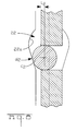
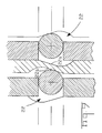
- the present invention has also been designed to accommodate a range of wire sizes, the wire receiving channels 22 are profiled to receive and align conductors of various diameters, as shown in Figures 7 and 8. This has been accomplished by providing a wire receiving channel 22 extending vertically within the side walls 24a, 24b of the terminal receiving cavity 22 as shown in Figures 5 and 7.
- the wire receiving channel 22 first includes radiused sections 22b which are continuous with planar surfaces 22a. As shown in Figure 7, the worst condition of termination is shown where the electrical terminal 70 is right justified within the terminal receiving cavity 24 whereas the conductor C 1 is left justified within the conductor receiving channel 22.
- the planar surface 22a positions the conductor by providing a tangent surface to the conductor C 1 to prevent the conductor C 1 from moving further to the left.
- planar surfaces 22a provide tangent surfaces which are within the radius of curvature of the path formed by arcs 22b. As shown in Figure 7, even with the worst case condition, the electrical terminal continues to have an overlap from the edge of the terminal to the center of the conductor, of a distance L, . Since there is an offset L, , the conductor C 1 is mainly gripped between the two opposed contacts 82, 78; rather than relying on the plastic of the housing for a contact force. The planar surfaces 22a are only used for alignment.
- a small conductor C 2 having a diameter D 2 can also be terminated within the connector again with the surface 22a positioning the conductor within the wire receiving channel 22 with the overlap of the edge of the terminal and the center of the conductor of a distance L 2 .
- this electrical connector can terminate electrical conductors having diameters which are larger than the thickness of the electrical terminals (t), which allows for a very dense connection system on very close centerlines. Also, since the contacts are edge stamped, as opposed to stamped and formed, the contacts can also be placed on very close centerlines. Since the contacts are edge stamped, the normal force is much higher than a comparably sized stamped and formed terminal.
Landscapes
- Coupling Device And Connection With Printed Circuit (AREA)
- Multi-Conductor Connections (AREA)
Applications Claiming Priority (5)
| Application Number | Priority Date | Filing Date | Title |
|---|---|---|---|
| GB8904500 | 1989-02-28 | ||
| GB898904502A GB8904502D0 (en) | 1989-02-28 | 1989-02-28 | Zero insertion force connector for cable to board applications |
| GB8904502 | 1989-02-28 | ||
| GB898904500A GB8904500D0 (en) | 1989-02-28 | 1989-02-28 | Zero insertion force connector for cable to board applications |
| EP90103582A EP0385314B1 (fr) | 1989-02-28 | 1990-02-23 | Connecteur à force d'insertion nulle pour des applications de câbles à plaquette |
Related Parent Applications (2)
| Application Number | Title | Priority Date | Filing Date |
|---|---|---|---|
| EP90103582.4 Division | 1990-02-23 | ||
| EP90103582A Division EP0385314B1 (fr) | 1989-02-28 | 1990-02-23 | Connecteur à force d'insertion nulle pour des applications de câbles à plaquette |
Publications (3)
| Publication Number | Publication Date |
|---|---|
| EP0603161A2 true EP0603161A2 (fr) | 1994-06-22 |
| EP0603161A3 EP0603161A3 (en) | 1997-01-08 |
| EP0603161B1 EP0603161B1 (fr) | 1999-09-22 |
Family
ID=26295028
Family Applications (2)
| Application Number | Title | Priority Date | Filing Date |
|---|---|---|---|
| EP90103582A Expired - Lifetime EP0385314B1 (fr) | 1989-02-28 | 1990-02-23 | Connecteur à force d'insertion nulle pour des applications de câbles à plaquette |
| EP94103475A Expired - Lifetime EP0603161B1 (fr) | 1989-02-28 | 1990-02-23 | Connecteur à force d'insertion nulle pour des applications de câble à plaquette |
Family Applications Before (1)
| Application Number | Title | Priority Date | Filing Date |
|---|---|---|---|
| EP90103582A Expired - Lifetime EP0385314B1 (fr) | 1989-02-28 | 1990-02-23 | Connecteur à force d'insertion nulle pour des applications de câbles à plaquette |
Country Status (9)
| Country | Link |
|---|---|
| EP (2) | EP0385314B1 (fr) |
| JP (1) | JP2965210B2 (fr) |
| KR (1) | KR900013673A (fr) |
| CN (1) | CN1045314A (fr) |
| AR (1) | AR242322A1 (fr) |
| BR (1) | BR9000837A (fr) |
| DE (2) | DE69020382T2 (fr) |
| ES (1) | ES2074094T3 (fr) |
| MY (1) | MY106680A (fr) |
Families Citing this family (11)
| Publication number | Priority date | Publication date | Assignee | Title |
|---|---|---|---|---|
| JP2553439Y2 (ja) * | 1989-07-27 | 1997-11-05 | 日本エー・エム・ピー 株式会社 | 電気コネクタ |
| GB8921633D0 (en) * | 1989-09-25 | 1989-11-08 | Amp Holland | Zero insertion force connector for cable board applications |
| US5240430A (en) * | 1991-10-31 | 1993-08-31 | Amp Incorporated | Electrical connector for cable to circit board application |
| JP2571755Y2 (ja) * | 1992-04-24 | 1998-05-18 | 住鉱テック 株式会社 | フラットケーブル用コネクタ |
| US5226824A (en) * | 1992-05-13 | 1993-07-13 | Foxconn International, Inc. | IC socket and contact therein |
| JPH10340745A (ja) * | 1997-06-04 | 1998-12-22 | Kyoshin Kogyo Kk | ワンタッチコネクタおよびワンタッチコネクタ組合せ体 |
| KR100758183B1 (ko) * | 2007-05-03 | 2007-09-12 | 서교정보통신 주식회사 | 데이터 속도 분할 전송 장치 및 그 방법 |
| JP5694672B2 (ja) * | 2010-02-25 | 2015-04-01 | スリーエム イノベイティブ プロパティズ カンパニー | 接触子および電気コネクタ |
| US9553387B2 (en) * | 2014-07-15 | 2017-01-24 | Industria Lombarda Materiale Elettrico—I.L.M.E. S.P.A. | Electrical connecting device with spring connection element and compact actuator and multi-pole plug connector comprising a plurality of said spring contacts |
| CN110247331B (zh) * | 2018-03-09 | 2024-08-20 | 南京大全电气研究院有限公司 | 可移动式进线装置 |
| CN109548309B (zh) * | 2019-01-02 | 2020-09-22 | 浪潮商用机器有限公司 | 一种压力曲线设定方法及装置 |
Family Cites Families (11)
| Publication number | Priority date | Publication date | Assignee | Title |
|---|---|---|---|---|
| US3763459A (en) * | 1971-06-17 | 1973-10-02 | Textool Prod Inc | Plug-in type sockets for testing semiconductors |
| DE7705029U1 (de) * | 1976-02-20 | 1977-06-02 | Japan Aviation Electronics Industry, Ltd., Tokio | Ko nta ktverbindu ngsele me nt |
| US4377318A (en) * | 1978-02-06 | 1983-03-22 | Everett/Charles, Inc. | Low insertion force electrical interface assembly and actuable interface assembly therefor |
| JPS603748B2 (ja) * | 1978-11-18 | 1985-01-30 | 日本圧着端子製造株式会社 | コネクタ |
| JPS5692366U (fr) * | 1979-12-18 | 1981-07-23 | ||
| US4496205A (en) * | 1982-07-23 | 1985-01-29 | Thomas & Betts Corporation | Low or zero insertion force connector for multi-pin arrays |
| JPS58106779A (ja) * | 1981-12-18 | 1983-06-25 | 富士通株式会社 | シ−ルド線付同軸細線の端末処理方法 |
| JPS6026777U (ja) * | 1983-08-01 | 1985-02-23 | イ−・アイ・デュ・ポン・ドウ・ヌム−ル・アンド・カンパニ− | 電気コネクタ− |
| JPS6293964A (ja) * | 1985-10-21 | 1987-04-30 | Dai Ichi Seiko Co Ltd | Ic検査用ソケツト |
| JPH043422Y2 (fr) * | 1987-03-09 | 1992-02-03 | ||
| DE8816214U1 (de) * | 1987-12-30 | 1989-03-30 | Lotter, Karl, 8959 Buching | Leiterplattenverbinder zur lösbaren Verbindung von insbesondere zwei Leiterplatten |
-
1990
- 1990-02-15 MY MYPI90000250A patent/MY106680A/en unknown
- 1990-02-20 AR AR90316207A patent/AR242322A1/es active
- 1990-02-21 BR BR909000837A patent/BR9000837A/pt not_active IP Right Cessation
- 1990-02-23 DE DE69020382T patent/DE69020382T2/de not_active Expired - Fee Related
- 1990-02-23 EP EP90103582A patent/EP0385314B1/fr not_active Expired - Lifetime
- 1990-02-23 ES ES90103582T patent/ES2074094T3/es not_active Expired - Lifetime
- 1990-02-23 EP EP94103475A patent/EP0603161B1/fr not_active Expired - Lifetime
- 1990-02-23 DE DE69033300T patent/DE69033300T2/de not_active Expired - Fee Related
- 1990-02-27 CN CN90100980A patent/CN1045314A/zh active Pending
- 1990-02-28 KR KR1019900002627A patent/KR900013673A/ko not_active Ceased
- 1990-02-28 JP JP2046033A patent/JP2965210B2/ja not_active Expired - Fee Related
Also Published As
| Publication number | Publication date |
|---|---|
| EP0385314A1 (fr) | 1990-09-05 |
| DE69033300T2 (de) | 2000-04-13 |
| CN1045314A (zh) | 1990-09-12 |
| EP0603161A3 (en) | 1997-01-08 |
| KR900013673A (ko) | 1990-09-06 |
| DE69033300D1 (de) | 1999-10-28 |
| ES2074094T3 (es) | 1995-09-01 |
| DE69020382T2 (de) | 1995-11-02 |
| JP2965210B2 (ja) | 1999-10-18 |
| MY106680A (en) | 1995-07-31 |
| DE69020382D1 (de) | 1995-08-03 |
| AR242322A1 (es) | 1993-03-31 |
| EP0603161B1 (fr) | 1999-09-22 |
| JPH02273477A (ja) | 1990-11-07 |
| EP0385314B1 (fr) | 1995-06-28 |
| BR9000837A (pt) | 1991-10-15 |
Similar Documents
| Publication | Publication Date | Title |
|---|---|---|
| US5240430A (en) | Electrical connector for cable to circit board application | |
| CA1046146A (fr) | Connecteur electrique servant a relier un cable en nappe a un plaquette de circuits imprimes | |
| US5173058A (en) | Zero insertion force electrical connector | |
| EP0519196B1 (fr) | Bloc de bornes pour cartes à circuit imprimé | |
| US5882227A (en) | Controlled impedance connector block | |
| EP1368859B1 (fr) | Bloc terminal de connecteur de deplacement d'isolation | |
| US5536182A (en) | Insulation displacement connector | |
| KR0110997Y1 (ko) | 접속기 | |
| CA1274290A (fr) | Connecteur de cables | |
| EP0540260B1 (fr) | Connecteur électrique pour connecter une plaquette à circuits imprimés avec un câble | |
| EP0420009B1 (fr) | Connecteur à force d'insertion nulle pour connecter des câbles à des plaques de circuit | |
| CA2015898C (fr) | Connecteur de cable plat a grande densite | |
| US4508410A (en) | Electrical termination system and connector member | |
| EP0603161B1 (fr) | Connecteur à force d'insertion nulle pour des applications de câble à plaquette | |
| US5921785A (en) | Electrical connector for flat cables | |
| US4921439A (en) | Center wire trap terminal and connector | |
| EP0340994B1 (fr) | Connecteur électrique à force d'insertion nulle | |
| EP0194052B1 (fr) | Connecteur électrique pour connecter de multiples broches montées sur une carte de circuit imprimé avec un câble plat multiconducteur | |
| EP0109297B1 (fr) | Eléments de contacts électriques et d'assemblages de connecteurs électriques | |
| CA1183919A (fr) | Plaquette de raccordement multiborne a broches de branchement par fils boudines | |
| US3977754A (en) | Electrical connector | |
| US5114362A (en) | High density electrical connector and method of making a high density electrical connector | |
| US6162076A (en) | Electrical shorting assembly for electrical jacks and the like | |
| EP0385019B1 (fr) | Connecteur électrique à terminaux précontraints et méthode de fabrication | |
| CA1099798A (fr) | Traduction non-disponible |
Legal Events
| Date | Code | Title | Description |
|---|---|---|---|
| PUAI | Public reference made under article 153(3) epc to a published international application that has entered the european phase |
Free format text: ORIGINAL CODE: 0009012 |
|
| 17P | Request for examination filed |
Effective date: 19940308 |
|
| AC | Divisional application: reference to earlier application |
Ref document number: 385314 Country of ref document: EP |
|
| AK | Designated contracting states |
Kind code of ref document: A2 Designated state(s): BE CH DE ES FR GB IT LI NL SE |
|
| PUAL | Search report despatched |
Free format text: ORIGINAL CODE: 0009013 |
|
| AK | Designated contracting states |
Kind code of ref document: A3 Designated state(s): BE CH DE ES FR GB IT LI NL SE |
|
| 17Q | First examination report despatched |
Effective date: 19980818 |
|
| GRAG | Despatch of communication of intention to grant |
Free format text: ORIGINAL CODE: EPIDOS AGRA |
|
| GRAG | Despatch of communication of intention to grant |
Free format text: ORIGINAL CODE: EPIDOS AGRA |
|
| GRAH | Despatch of communication of intention to grant a patent |
Free format text: ORIGINAL CODE: EPIDOS IGRA |
|
| GRAG | Despatch of communication of intention to grant |
Free format text: ORIGINAL CODE: EPIDOS AGRA |
|
| GRAH | Despatch of communication of intention to grant a patent |
Free format text: ORIGINAL CODE: EPIDOS IGRA |
|
| GRAA | (expected) grant |
Free format text: ORIGINAL CODE: 0009210 |
|
| AC | Divisional application: reference to earlier application |
Ref document number: 385314 Country of ref document: EP |
|
| AK | Designated contracting states |
Kind code of ref document: B1 Designated state(s): BE CH DE ES FR GB IT LI NL SE |
|
| PG25 | Lapsed in a contracting state [announced via postgrant information from national office to epo] |
Ref country code: SE Free format text: THE PATENT HAS BEEN ANNULLED BY A DECISION OF A NATIONAL AUTHORITY Effective date: 19990922 Ref country code: NL Free format text: LAPSE BECAUSE OF FAILURE TO SUBMIT A TRANSLATION OF THE DESCRIPTION OR TO PAY THE FEE WITHIN THE PRESCRIBED TIME-LIMIT Effective date: 19990922 Ref country code: LI Free format text: LAPSE BECAUSE OF FAILURE TO SUBMIT A TRANSLATION OF THE DESCRIPTION OR TO PAY THE FEE WITHIN THE PRESCRIBED TIME-LIMIT Effective date: 19990922 Ref country code: IT Free format text: LAPSE BECAUSE OF FAILURE TO SUBMIT A TRANSLATION OF THE DESCRIPTION OR TO PAY THE FEE WITHIN THE PRE;WARNING: LAPSES OF ITALIAN PATENTS WITH EFFECTIVE DATE BEFORE 2007 MAY HAVE OCCURRED AT ANY TIME BEFORE 2007. THE CORRECT EFFECTIVE DATE MAY BE DIFFERENT FROM THE ONE RECORDED.SCRIBED TIME-LIMIT Effective date: 19990922 Ref country code: ES Free format text: THE PATENT HAS BEEN ANNULLED BY A DECISION OF A NATIONAL AUTHORITY Effective date: 19990922 Ref country code: CH Free format text: LAPSE BECAUSE OF FAILURE TO SUBMIT A TRANSLATION OF THE DESCRIPTION OR TO PAY THE FEE WITHIN THE PRESCRIBED TIME-LIMIT Effective date: 19990922 Ref country code: BE Free format text: LAPSE BECAUSE OF FAILURE TO SUBMIT A TRANSLATION OF THE DESCRIPTION OR TO PAY THE FEE WITHIN THE PRESCRIBED TIME-LIMIT Effective date: 19990922 |
|
| REG | Reference to a national code |
Ref country code: CH Ref legal event code: EP |
|
| REF | Corresponds to: |
Ref document number: 69033300 Country of ref document: DE Date of ref document: 19991028 |
|
| ET | Fr: translation filed | ||
| NLV1 | Nl: lapsed or annulled due to failure to fulfill the requirements of art. 29p and 29m of the patents act | ||
| REG | Reference to a national code |
Ref country code: CH Ref legal event code: PL |
|
| PLBE | No opposition filed within time limit |
Free format text: ORIGINAL CODE: 0009261 |
|
| STAA | Information on the status of an ep patent application or granted ep patent |
Free format text: STATUS: NO OPPOSITION FILED WITHIN TIME LIMIT |
|
| 26N | No opposition filed | ||
| REG | Reference to a national code |
Ref country code: GB Ref legal event code: IF02 |
|
| PGFP | Annual fee paid to national office [announced via postgrant information from national office to epo] |
Ref country code: GB Payment date: 20040107 Year of fee payment: 15 |
|
| PGFP | Annual fee paid to national office [announced via postgrant information from national office to epo] |
Ref country code: FR Payment date: 20040202 Year of fee payment: 15 |
|
| PGFP | Annual fee paid to national office [announced via postgrant information from national office to epo] |
Ref country code: DE Payment date: 20040227 Year of fee payment: 15 |
|
| PG25 | Lapsed in a contracting state [announced via postgrant information from national office to epo] |
Ref country code: GB Free format text: LAPSE BECAUSE OF NON-PAYMENT OF DUE FEES Effective date: 20050223 |
|
| PG25 | Lapsed in a contracting state [announced via postgrant information from national office to epo] |
Ref country code: DE Free format text: LAPSE BECAUSE OF NON-PAYMENT OF DUE FEES Effective date: 20050901 |
|
| GBPC | Gb: european patent ceased through non-payment of renewal fee |
Effective date: 20050222 |
|
| PG25 | Lapsed in a contracting state [announced via postgrant information from national office to epo] |
Ref country code: FR Free format text: LAPSE BECAUSE OF NON-PAYMENT OF DUE FEES Effective date: 20051031 |
|
| REG | Reference to a national code |
Ref country code: FR Ref legal event code: ST Effective date: 20051031 |