EP0603182B1 - Flüssigkeitskühler - Google Patents
Flüssigkeitskühler Download PDFInfo
- Publication number
- EP0603182B1 EP0603182B1 EP92911026A EP92911026A EP0603182B1 EP 0603182 B1 EP0603182 B1 EP 0603182B1 EP 92911026 A EP92911026 A EP 92911026A EP 92911026 A EP92911026 A EP 92911026A EP 0603182 B1 EP0603182 B1 EP 0603182B1
- Authority
- EP
- European Patent Office
- Prior art keywords
- liquid
- cooler
- cold
- conduit means
- cooling system
- Prior art date
- Legal status (The legal status is an assumption and is not a legal conclusion. Google has not performed a legal analysis and makes no representation as to the accuracy of the status listed.)
- Expired - Lifetime
Links
- 239000007788 liquid Substances 0.000 title claims abstract description 284
- 238000001816 cooling Methods 0.000 claims abstract description 88
- 238000007906 compression Methods 0.000 claims abstract description 13
- 238000010521 absorption reaction Methods 0.000 claims abstract description 12
- 230000004888 barrier function Effects 0.000 claims abstract description 7
- XLYOFNOQVPJJNP-UHFFFAOYSA-N water Substances O XLYOFNOQVPJJNP-UHFFFAOYSA-N 0.000 claims description 198
- 239000003507 refrigerant Substances 0.000 claims description 81
- 239000013078 crystal Substances 0.000 claims description 59
- 239000000203 mixture Substances 0.000 claims description 48
- 238000010438 heat treatment Methods 0.000 claims description 38
- 239000013526 supercooled liquid Substances 0.000 claims description 38
- 239000012071 phase Substances 0.000 claims description 34
- 230000008859 change Effects 0.000 claims description 31
- 239000002002 slurry Substances 0.000 claims description 29
- 238000004781 supercooling Methods 0.000 claims description 23
- 239000007787 solid Substances 0.000 claims description 22
- 238000012546 transfer Methods 0.000 claims description 16
- 241000251468 Actinopterygii Species 0.000 claims description 13
- 239000010797 grey water Substances 0.000 claims description 12
- 239000000463 material Substances 0.000 claims description 12
- 238000002425 crystallisation Methods 0.000 claims description 10
- 230000008025 crystallization Effects 0.000 claims description 9
- 238000009833 condensation Methods 0.000 claims description 8
- 230000005494 condensation Effects 0.000 claims description 8
- 230000003750 conditioning effect Effects 0.000 claims description 8
- 239000013505 freshwater Substances 0.000 claims description 7
- 239000007791 liquid phase Substances 0.000 claims description 7
- 239000011810 insulating material Substances 0.000 claims description 6
- 239000012808 vapor phase Substances 0.000 claims description 6
- 241000533950 Leucojum Species 0.000 claims description 5
- 230000015572 biosynthetic process Effects 0.000 claims description 5
- 239000012528 membrane Substances 0.000 claims description 5
- 238000002156 mixing Methods 0.000 claims description 5
- 238000009877 rendering Methods 0.000 claims description 5
- 238000011144 upstream manufacturing Methods 0.000 claims description 5
- 238000005304 joining Methods 0.000 claims description 2
- 239000011343 solid material Substances 0.000 claims description 2
- 238000013461 design Methods 0.000 abstract description 37
- 238000009434 installation Methods 0.000 abstract description 10
- 230000006872 improvement Effects 0.000 abstract description 7
- 238000005516 engineering process Methods 0.000 abstract description 4
- 230000006835 compression Effects 0.000 abstract description 2
- 230000008030 elimination Effects 0.000 abstract 1
- 238000003379 elimination reaction Methods 0.000 abstract 1
- 239000012530 fluid Substances 0.000 description 49
- 238000000034 method Methods 0.000 description 43
- 238000007710 freezing Methods 0.000 description 20
- 230000008014 freezing Effects 0.000 description 20
- 230000008569 process Effects 0.000 description 19
- 238000001704 evaporation Methods 0.000 description 9
- 239000000498 cooling water Substances 0.000 description 8
- 230000002829 reductive effect Effects 0.000 description 8
- 239000000243 solution Substances 0.000 description 7
- 230000008901 benefit Effects 0.000 description 6
- 238000009413 insulation Methods 0.000 description 6
- 239000004033 plastic Substances 0.000 description 6
- 229920003023 plastic Polymers 0.000 description 6
- 230000000694 effects Effects 0.000 description 5
- 230000008020 evaporation Effects 0.000 description 5
- 230000004048 modification Effects 0.000 description 5
- 238000012986 modification Methods 0.000 description 5
- 238000005086 pumping Methods 0.000 description 5
- 238000000926 separation method Methods 0.000 description 5
- 238000010276 construction Methods 0.000 description 4
- 238000000605 extraction Methods 0.000 description 4
- 238000004519 manufacturing process Methods 0.000 description 4
- 229910052751 metal Inorganic materials 0.000 description 4
- 239000002184 metal Substances 0.000 description 4
- 238000005057 refrigeration Methods 0.000 description 4
- 239000000126 substance Substances 0.000 description 4
- OKKJLVBELUTLKV-UHFFFAOYSA-N Methanol Chemical compound OC OKKJLVBELUTLKV-UHFFFAOYSA-N 0.000 description 3
- 230000009471 action Effects 0.000 description 3
- 238000005054 agglomeration Methods 0.000 description 3
- 230000002776 aggregation Effects 0.000 description 3
- 238000009360 aquaculture Methods 0.000 description 3
- 244000144974 aquaculture Species 0.000 description 3
- 238000004140 cleaning Methods 0.000 description 3
- 239000012141 concentrate Substances 0.000 description 3
- 239000002826 coolant Substances 0.000 description 3
- 230000003628 erosive effect Effects 0.000 description 3
- 238000003306 harvesting Methods 0.000 description 3
- 241000196324 Embryophyta Species 0.000 description 2
- LYCAIKOWRPUZTN-UHFFFAOYSA-N Ethylene glycol Chemical compound OCCO LYCAIKOWRPUZTN-UHFFFAOYSA-N 0.000 description 2
- 239000002253 acid Substances 0.000 description 2
- 150000007513 acids Chemical class 0.000 description 2
- 239000000654 additive Substances 0.000 description 2
- 238000004378 air conditioning Methods 0.000 description 2
- 239000012267 brine Substances 0.000 description 2
- 230000003247 decreasing effect Effects 0.000 description 2
- 238000010586 diagram Methods 0.000 description 2
- 238000009826 distribution Methods 0.000 description 2
- 238000004146 energy storage Methods 0.000 description 2
- 239000000284 extract Substances 0.000 description 2
- 239000000446 fuel Substances 0.000 description 2
- 230000005484 gravity Effects 0.000 description 2
- 239000012212 insulator Substances 0.000 description 2
- 238000002844 melting Methods 0.000 description 2
- VNWKTOKETHGBQD-UHFFFAOYSA-N methane Chemical compound C VNWKTOKETHGBQD-UHFFFAOYSA-N 0.000 description 2
- 238000010899 nucleation Methods 0.000 description 2
- 239000003973 paint Substances 0.000 description 2
- 230000005855 radiation Effects 0.000 description 2
- HPALAKNZSZLMCH-UHFFFAOYSA-M sodium;chloride;hydrate Chemical compound O.[Na+].[Cl-] HPALAKNZSZLMCH-UHFFFAOYSA-M 0.000 description 2
- 239000002904 solvent Substances 0.000 description 2
- 239000007921 spray Substances 0.000 description 2
- 238000003860 storage Methods 0.000 description 2
- 238000012360 testing method Methods 0.000 description 2
- 241000711969 Chandipura virus Species 0.000 description 1
- 229920000742 Cotton Polymers 0.000 description 1
- 208000015951 Cytophagic histiocytic panniculitis Diseases 0.000 description 1
- 241001057440 Didion Species 0.000 description 1
- JYGLAHSAISAEAL-UHFFFAOYSA-N Diphenadione Chemical compound O=C1C2=CC=CC=C2C(=O)C1C(=O)C(C=1C=CC=CC=1)C1=CC=CC=C1 JYGLAHSAISAEAL-UHFFFAOYSA-N 0.000 description 1
- JOYRKODLDBILNP-UHFFFAOYSA-N Ethyl urethane Chemical compound CCOC(N)=O JOYRKODLDBILNP-UHFFFAOYSA-N 0.000 description 1
- 229920005830 Polyurethane Foam Polymers 0.000 description 1
- FAPWRFPIFSIZLT-UHFFFAOYSA-M Sodium chloride Chemical compound [Na+].[Cl-] FAPWRFPIFSIZLT-UHFFFAOYSA-M 0.000 description 1
- 230000006978 adaptation Effects 0.000 description 1
- 230000002411 adverse Effects 0.000 description 1
- 239000003513 alkali Substances 0.000 description 1
- 239000004411 aluminium Substances 0.000 description 1
- 229910052782 aluminium Inorganic materials 0.000 description 1
- XAGFODPZIPBFFR-UHFFFAOYSA-N aluminium Chemical compound [Al] XAGFODPZIPBFFR-UHFFFAOYSA-N 0.000 description 1
- 230000003466 anti-cipated effect Effects 0.000 description 1
- 238000009835 boiling Methods 0.000 description 1
- 235000012206 bottled water Nutrition 0.000 description 1
- 238000005119 centrifugation Methods 0.000 description 1
- 230000001143 conditioned effect Effects 0.000 description 1
- 238000011217 control strategy Methods 0.000 description 1
- 238000007796 conventional method Methods 0.000 description 1
- 239000000110 cooling liquid Substances 0.000 description 1
- 239000013256 coordination polymer Substances 0.000 description 1
- 238000005260 corrosion Methods 0.000 description 1
- 238000000151 deposition Methods 0.000 description 1
- 238000010612 desalination reaction Methods 0.000 description 1
- 239000002270 dispersing agent Substances 0.000 description 1
- 239000003651 drinking water Substances 0.000 description 1
- 230000003670 easy-to-clean Effects 0.000 description 1
- 238000002474 experimental method Methods 0.000 description 1
- 238000011049 filling Methods 0.000 description 1
- 238000001914 filtration Methods 0.000 description 1
- 238000007667 floating Methods 0.000 description 1
- 239000006260 foam Substances 0.000 description 1
- 230000006870 function Effects 0.000 description 1
- 239000007789 gas Substances 0.000 description 1
- 150000008282 halocarbons Chemical class 0.000 description 1
- WGCNASOHLSPBMP-UHFFFAOYSA-N hydroxyacetaldehyde Natural products OCC=O WGCNASOHLSPBMP-UHFFFAOYSA-N 0.000 description 1
- 239000011261 inert gas Substances 0.000 description 1
- 230000000977 initiatory effect Effects 0.000 description 1
- 238000007689 inspection Methods 0.000 description 1
- AMXOYNBUYSYVKV-UHFFFAOYSA-M lithium bromide Inorganic materials [Li+].[Br-] AMXOYNBUYSYVKV-UHFFFAOYSA-M 0.000 description 1
- 230000007774 longterm Effects 0.000 description 1
- 230000008018 melting Effects 0.000 description 1
- 150000002739 metals Chemical class 0.000 description 1
- 239000008267 milk Substances 0.000 description 1
- 210000004080 milk Anatomy 0.000 description 1
- 235000013336 milk Nutrition 0.000 description 1
- 239000003345 natural gas Substances 0.000 description 1
- 230000036961 partial effect Effects 0.000 description 1
- 239000002245 particle Substances 0.000 description 1
- IUGYQRQAERSCNH-UHFFFAOYSA-N pivalic acid Chemical compound CC(C)(C)C(O)=O IUGYQRQAERSCNH-UHFFFAOYSA-N 0.000 description 1
- 239000011496 polyurethane foam Substances 0.000 description 1
- 239000011148 porous material Substances 0.000 description 1
- 230000008092 positive effect Effects 0.000 description 1
- 230000002265 prevention Effects 0.000 description 1
- 230000001902 propagating effect Effects 0.000 description 1
- 150000003839 salts Chemical class 0.000 description 1
- 239000013535 sea water Substances 0.000 description 1
- 230000001932 seasonal effect Effects 0.000 description 1
- 230000035939 shock Effects 0.000 description 1
- 239000011780 sodium chloride Substances 0.000 description 1
- 238000005507 spraying Methods 0.000 description 1
- 239000008399 tap water Substances 0.000 description 1
- 235000020679 tap water Nutrition 0.000 description 1
- 230000009466 transformation Effects 0.000 description 1
- 150000003673 urethanes Chemical class 0.000 description 1
- 238000005406 washing Methods 0.000 description 1
- 239000002351 wastewater Substances 0.000 description 1
- 230000003442 weekly effect Effects 0.000 description 1
Images


Classifications
-
- F—MECHANICAL ENGINEERING; LIGHTING; HEATING; WEAPONS; BLASTING
- F28—HEAT EXCHANGE IN GENERAL
- F28F—DETAILS OF HEAT-EXCHANGE AND HEAT-TRANSFER APPARATUS, OF GENERAL APPLICATION
- F28F9/00—Casings; Header boxes; Auxiliary supports for elements; Auxiliary members within casings
- F28F9/02—Header boxes; End plates
- F28F9/026—Header boxes; End plates with static flow control means, e.g. with means for uniformly distributing heat exchange media into conduits
- F28F9/027—Header boxes; End plates with static flow control means, e.g. with means for uniformly distributing heat exchange media into conduits in the form of distribution pipes
- F28F9/0275—Header boxes; End plates with static flow control means, e.g. with means for uniformly distributing heat exchange media into conduits in the form of distribution pipes with multiple branch pipes
-
- F—MECHANICAL ENGINEERING; LIGHTING; HEATING; WEAPONS; BLASTING
- F25—REFRIGERATION OR COOLING; COMBINED HEATING AND REFRIGERATION SYSTEMS; HEAT PUMP SYSTEMS; MANUFACTURE OR STORAGE OF ICE; LIQUEFACTION SOLIDIFICATION OF GASES
- F25B—REFRIGERATION MACHINES, PLANTS OR SYSTEMS; COMBINED HEATING AND REFRIGERATION SYSTEMS; HEAT PUMP SYSTEMS
- F25B39/00—Evaporators; Condensers
- F25B39/02—Evaporators
-
- F—MECHANICAL ENGINEERING; LIGHTING; HEATING; WEAPONS; BLASTING
- F25—REFRIGERATION OR COOLING; COMBINED HEATING AND REFRIGERATION SYSTEMS; HEAT PUMP SYSTEMS; MANUFACTURE OR STORAGE OF ICE; LIQUEFACTION SOLIDIFICATION OF GASES
- F25B—REFRIGERATION MACHINES, PLANTS OR SYSTEMS; COMBINED HEATING AND REFRIGERATION SYSTEMS; HEAT PUMP SYSTEMS
- F25B47/00—Arrangements for preventing or removing deposits or corrosion, not provided for in another subclass
- F25B47/006—Arrangements for preventing or removing deposits or corrosion, not provided for in another subclass for preventing frost
-
- F—MECHANICAL ENGINEERING; LIGHTING; HEATING; WEAPONS; BLASTING
- F25—REFRIGERATION OR COOLING; COMBINED HEATING AND REFRIGERATION SYSTEMS; HEAT PUMP SYSTEMS; MANUFACTURE OR STORAGE OF ICE; LIQUEFACTION SOLIDIFICATION OF GASES
- F25C—PRODUCING, WORKING OR HANDLING ICE
- F25C1/00—Producing ice
- F25C1/04—Producing ice by using stationary moulds
- F25C1/06—Producing ice by using stationary moulds open or openable at both ends
-
- F—MECHANICAL ENGINEERING; LIGHTING; HEATING; WEAPONS; BLASTING
- F25—REFRIGERATION OR COOLING; COMBINED HEATING AND REFRIGERATION SYSTEMS; HEAT PUMP SYSTEMS; MANUFACTURE OR STORAGE OF ICE; LIQUEFACTION SOLIDIFICATION OF GASES
- F25C—PRODUCING, WORKING OR HANDLING ICE
- F25C3/00—Processes or apparatus specially adapted for producing ice or snow for winter sports or similar recreational purposes, e.g. for sporting installations; Producing artificial snow
- F25C3/04—Processes or apparatus specially adapted for producing ice or snow for winter sports or similar recreational purposes, e.g. for sporting installations; Producing artificial snow for sledging or ski trails; Producing artificial snow
-
- F—MECHANICAL ENGINEERING; LIGHTING; HEATING; WEAPONS; BLASTING
- F25—REFRIGERATION OR COOLING; COMBINED HEATING AND REFRIGERATION SYSTEMS; HEAT PUMP SYSTEMS; MANUFACTURE OR STORAGE OF ICE; LIQUEFACTION SOLIDIFICATION OF GASES
- F25D—REFRIGERATORS; COLD ROOMS; ICE-BOXES; COOLING OR FREEZING APPARATUS NOT OTHERWISE PROVIDED FOR
- F25D31/00—Other cooling or freezing apparatus
-
- F—MECHANICAL ENGINEERING; LIGHTING; HEATING; WEAPONS; BLASTING
- F28—HEAT EXCHANGE IN GENERAL
- F28D—HEAT-EXCHANGE APPARATUS, NOT PROVIDED FOR IN ANOTHER SUBCLASS, IN WHICH THE HEAT-EXCHANGE MEDIA DO NOT COME INTO DIRECT CONTACT
- F28D7/00—Heat-exchange apparatus having stationary tubular conduit assemblies for both heat-exchange media, the media being in contact with different sides of a conduit wall
- F28D7/16—Heat-exchange apparatus having stationary tubular conduit assemblies for both heat-exchange media, the media being in contact with different sides of a conduit wall the conduits being arranged in parallel spaced relation
-
- F—MECHANICAL ENGINEERING; LIGHTING; HEATING; WEAPONS; BLASTING
- F28—HEAT EXCHANGE IN GENERAL
- F28F—DETAILS OF HEAT-EXCHANGE AND HEAT-TRANSFER APPARATUS, OF GENERAL APPLICATION
- F28F19/00—Preventing the formation of deposits or corrosion, e.g. by using filters or scrapers
- F28F19/006—Preventing deposits of ice
-
- F—MECHANICAL ENGINEERING; LIGHTING; HEATING; WEAPONS; BLASTING
- F28—HEAT EXCHANGE IN GENERAL
- F28F—DETAILS OF HEAT-EXCHANGE AND HEAT-TRANSFER APPARATUS, OF GENERAL APPLICATION
- F28F9/00—Casings; Header boxes; Auxiliary supports for elements; Auxiliary members within casings
- F28F9/02—Header boxes; End plates
- F28F9/0229—Double end plates; Single end plates with hollow spaces
-
- F—MECHANICAL ENGINEERING; LIGHTING; HEATING; WEAPONS; BLASTING
- F25—REFRIGERATION OR COOLING; COMBINED HEATING AND REFRIGERATION SYSTEMS; HEAT PUMP SYSTEMS; MANUFACTURE OR STORAGE OF ICE; LIQUEFACTION SOLIDIFICATION OF GASES
- F25B—REFRIGERATION MACHINES, PLANTS OR SYSTEMS; COMBINED HEATING AND REFRIGERATION SYSTEMS; HEAT PUMP SYSTEMS
- F25B2339/00—Details of evaporators; Details of condensers
- F25B2339/02—Details of evaporators
- F25B2339/024—Evaporators with refrigerant in a vessel in which is situated a heat exchanger
- F25B2339/0242—Evaporators with refrigerant in a vessel in which is situated a heat exchanger having tubular elements
-
- F—MECHANICAL ENGINEERING; LIGHTING; HEATING; WEAPONS; BLASTING
- F25—REFRIGERATION OR COOLING; COMBINED HEATING AND REFRIGERATION SYSTEMS; HEAT PUMP SYSTEMS; MANUFACTURE OR STORAGE OF ICE; LIQUEFACTION SOLIDIFICATION OF GASES
- F25C—PRODUCING, WORKING OR HANDLING ICE
- F25C2303/00—Special arrangements or features for producing ice or snow for winter sports or similar recreational purposes, e.g. for sporting installations; Special arrangements or features for producing artificial snow
- F25C2303/048—Snow making by using means for spraying water
-
- Y—GENERAL TAGGING OF NEW TECHNOLOGICAL DEVELOPMENTS; GENERAL TAGGING OF CROSS-SECTIONAL TECHNOLOGIES SPANNING OVER SEVERAL SECTIONS OF THE IPC; TECHNICAL SUBJECTS COVERED BY FORMER USPC CROSS-REFERENCE ART COLLECTIONS [XRACs] AND DIGESTS
- Y02—TECHNOLOGIES OR APPLICATIONS FOR MITIGATION OR ADAPTATION AGAINST CLIMATE CHANGE
- Y02P—CLIMATE CHANGE MITIGATION TECHNOLOGIES IN THE PRODUCTION OR PROCESSING OF GOODS
- Y02P60/00—Technologies relating to agriculture, livestock or agroalimentary industries
- Y02P60/80—Food processing, e.g. use of renewable energies or variable speed drives in handling, conveying or stacking
- Y02P60/85—Food storage or conservation, e.g. cooling or drying
Definitions
- This invention relates to a liquid-cooling system for cooling any liquid, said cooling being performed for any purpose, including the extraction of energy from said liquid for heating purposes. More particularly, this invention is concerned with a simple and efficient system for obtaining and handling very cold liquids, down to and below their solid-liquid equilibrium temperature.
- a cooler is a component of a liquid-chilling system in which a liquid, usually an aqueous liquid (e.g. water or brine), is cooled by a refrigerant.
- a liquid usually an aqueous liquid (e.g. water or brine)
- a refrigerant e.g. water or brine
- the cooling effect comes from the evaporation of said refrigerant.
- the most common cooler types are: direct expansion and flooded (1990 ASHRAE Handbook: Refrigeration Systems and Applications).
- the refrigerant evaporates inside tubes, while the fluid to be cooled is channeled throughout the shell by a series of baffles.
- the fluid, flowing through the tubes gives its heat to the boiling liquid refrigerant on the shell side.
- These coolers are usually mounted horizontally. They are normally found in larger systems using screw or centrifugal compressors. In very large diameter shells, the heat transfer at the bottom can be adversely affected by the head of the refrigerant. This problem can be solved by spraying the liquid refrigerant all over the tubes instead of flooding them.
- Freezing of the fluid can cause considerable damage to coolers therefore some freeze protection must be provided.
- Two methods are used. Suction pressure can be held above the one corresponding to the freezing point of the fluid; or the system can be shut down when the fluid temperature gets too close to the freezing point.
- an evaporator-outlet temperature of 5°C is often considered as a safe lower limit.
- a freeze-up will occur: the freezing process will start at a location where the wall temperature is well below phase-equilibrium temperature and where the fluid velocity is low.
- the flow of water in the tubes does not exhibit any low velocity region; except maybe at the inlet where the flow might be detached for a certain distance inside: a low velocity bubble is then created where freezing might start.
- the real problem is in the cooler heads, where low-velocity water is exposed to the cold tubesheets.
- the freezing process will start there if the tubesheet is at a temperature below freezing.
- a direct-expansion cooler several low water velocity regions exist in the shell, which is crossed by cold tubes containing the evaporating refrigerant.
- the cooler outlet on the fluid side will usually be kept at 7°C. Since the inlet is at about 13°C, a ⁇ T (temperature differential) of only 6°C is thus available for energy absorption. This is an important limitation. If the ⁇ T could be doubled (e.g. by using a cooler capable of generating 1°C fluid outlet temperatures), the system capacity could be doubled without even having to increase the size of the distribution system (pumps, piping and heat exchangers).
- the invention also provides a liquid cooler design in which outlet ends of individual conduit means extensions or outlet ends of main conduit means, from which the supercooled liquid flows, are equipped in such a way as to prevent the formation of ice crystals at said outlet ends, formation of said ice crystals caused by said outlet ends being colder than ambience; said prevention of crystallization being obtained, for example, by constructing said outlet ends of an anti-fogging material and/or by heating said outlet ends, using heat from any source, said heat being transfered to said outlet ends using any of the basic heat transfer modes.
- the invention provides a new liquid cooler design, said cooler being part of a low-temperature liquid cooling system, said cooler being connected to a liquid supply circuit including one or more conduit means through which said liquid flows, said conduit means passing through and being in contact with a cold medium in said cooler, said cooler being characterized by the presence of double tubesheet(s) at both ends, thus preventing the contact of the said liquid with a cold surface in regions where the said liquid is stagnant or has a low velocity as compared to the average liquid velocity inside the said conduit means passing through said cooler; said cooler also being characterized by the presence of cooler heads at each end, cooler head at the inlet end acting as flow distributor for said liquid arriving through inlet; cooler head at the oulet end acting as flow receiver for said liquid, said liquid then exiting through outlet.
- the invention provides a new liquid cooler design comprising a set of inner most tubesheets and also featuring around each conduit means a larger conduit means, the space between said inner and outer conduit means becoming the conduit means through which said cold medium flows and receives heat from fluid being cooled, the space between new inner most tubesheet and neighbouring tubesheet acting as a distributor for said liquid cooling medium after its entrance into said cooler, the space between new inner most tubesheet and neighbouring tubesheet acting as a receiver for said cooling medium, before its departure from said cooler, said cooler thus being converted into a shell-and-multi-double-tube cooler.
- the invention also provides a liquid cooler design characterized in the fact that each of said conduit means are extended past exterior tubesheet, the cooled fluid then being fed to a reservoir or anywhere it is needed by each conduit means extension individually; said extensions eliminating low liquid velocity regions near cold surfaces, thus rendering the presence of double tubesheet unnecessary; said cooler thus being transformed into a supercooler.
- the invention also provides a liquid cooler design in which the flows from two or more individual conduit means extensions, are instead joined together in order to create a larger flow of supercooled fluid inside a larger conduit means; said joining being preferably performed in such a way that the flows exiting from all of said extensions be essentially parrallel, ends of said extensions being possibly pressed one against the other, side-by-side, and introduced into said other larger conduit means or into a special fitting attached to said other larger conduit means.
- the invention also provides a liquid cooler design in which said cooler is the cold-side heat exchanger (CSHE) of a heat pump, said heat pump being of the vapor-compression heat pump (VCHP) type, the refrigerant used being of the non-azeotropic-mixture type; said heat pump being further characterized by the presence in the cycle of a reformer (LPR), said reformer being a reservoir capable of containing said refrigerant in liquid and vapor phases, said vapor from the top of said reformer (LPR) being entrained, compressed, condensed, and expanded in the hot side portion of the said circuit, said liquid from the bottom part of said reformer (LPR) being entrained, circulated and evaporated in the cold side portion of said heat pump circuit, said circulation in said cold side being produced by a refrigerant pump (P), said pump (P) being capable of producing an overfeeding of said cooler EV, the overfeed rate having any value including one, said pump (P) having a fixed or a variable speed, said
- the invention also provides a liquid cooler design in which said cooler is part of a low-temperature liquid cooling system in which a continuous flow of supercooled liquid water is changed into a flow of supercooled droplets using any convenient method, said change being a major perturbation, each of said supercooled droplets, because of said perturbation, then rapidly becoming droplets containing a mixture of dendritic ice and water, said ice part in said droplets then growing in ambiant cold air until said droplets become 100% ice crystals (i.e. snowflakes); or said droplets possibly used as seeders for larger cold or supercooled water droplets which will then grow into large snowflakes; said cooling system thus becoming a snow-making machine.
- said cooler is part of a low-temperature liquid cooling system in which a continuous flow of supercooled liquid water is changed into a flow of supercooled droplets using any convenient method, said change being a major perturbation, each of said supercooled droplets, because of said perturbation, then rapidly becoming droplets containing a mixture of dendritic ice and water,
- the invention also provides a liquid cooler design in which said cooler is part of a liquid supercooling system, said liquid exiting from said cooler being made to partially change phase, said phase change providing a mixture of solid and cold liquid at the phase-equilibrium temperature; the operating conditions of said system being modulated in order to modify the type of solid material generated during said phase change of said supercooled liquid, said conditions being mainly the temperature of supercooled liquid, a slight supercooling (e.g. at temperatures between 0°C and about -0,5°C for pure water) favouring the generation of hard crystals of any size and shape, said shape depending mainly on the way said solid/liquid mixture is handled; a "deep" supercooling (e.g.
- the invention also provides a liquid cooler design in which said cooler is the cold-side heat exchanger (CSHE) of a heat pump, said heat pump being of the hybrid-cascade type, comprising one (or more) absorption heat pump (AHP), said system also using one (or more) vapor-compression heat pump (VCHP), said AHP being normally unable to attain the low temperature necessary for providing desired final liquid states, said AHP being helped here by VCHP installed in cascade fashion with said AHP; the CSHE of said VCHP being capable of cooling the liquid exiting from AHP down to low temperatures, the capacity of AHP being large enough to provide chilled liquid both for hot-side heat exchanger (HSHE) of VCHP and for cold-side heat exchanger(s) (CSHE(s)) of VCHP; said low temperature liquid being sent to load and coming out as warmed liquid; the cooling liquid coming out of said HSHE as a warm liquid; warm liquids flows being joined into a larger flow of warm liquid which is sent back into the CSHE of the
- the invention provides a system for generating ice with a liquid cooler, said cooler possibly being the cold-side heat exchanger (CSHE) of a liquid chiller, said chiller being capable of cooling any liquid; said liquid being cooled by said cooler to supercooling temperatures; said exiting supercooled liquid being made to partially change phase; said phase change providing a mixture of solid and cold liquid at the phase-equilibrium temperature.
- CSHE cold-side heat exchanger
- the invention also provides a liquid cooler design in which said cooler is part of a freeze-concentration system where a slightly supercooled liquid is forced through a porous membrane, solid and porous ice then starting to build up all over said membrane, said membrane then acting as a crystallizer, said method providing a way of separating solids from liquids.
- the invention also provides a liquid cooler design in which said cooler is part of a liquid supercooling system where a continuous flow of supercooled liquid water is brought to a reservoir where it is changed into a mixture of ice crystals and water, said cristals slowly accumulating inside said reservoir, the mixture being kept homogeneous and in constant motion with the help of mixers of any type, including "egg-beaters", in such a way that crystal agglomerations are continuously broken-up, the resulting slurry, when needed, then being capable of easily flowing towards outlet of said reservoir and entering conduit means and then being pumped towards some other location, e.g. a reservoir in another building.
- the invention also provides a new cooler design in which said cooler is part of a liquid conditioning system, said system being used for heating liquids initially at or near their solid-liquid equilibrium temperature; said heating being performed using very little outside energy; said heating being performed using thermal energy still present in rejected liquid; said rejected liquid being still warm; most of said heating being performed in a passive way using a liquid-liquid heat exchanger (HX); said heating also being partly performed by the hot-side heat exchanger (HSHE) of a heat pump; said heat pump also having a cold-side heat exchanger (CSHE), said CSHE being capable, when necessary, to supercool said rejected liquid.
- HX liquid-liquid heat exchanger
- HX liquid-liquid heat exchanger
- HSHE hot-side heat exchanger
- CSHE cold-side heat exchanger
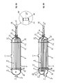
- FIGS. 1 and 2 show schematic diagrams of one-pass and two-pass flooded shell-and-tube coolers based on the present invention.
- Figures 3, 4, 5 and 6 show several alternative designs also based on the present invention.
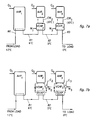
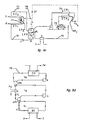
- Figures 7 and 9 show schematic diagrams of improved refrigeration cycles permitting an efficient generation of very cold liquid flows.
- Figures 8 and 10 show true counterflow coolers based on the present invention and capable of using, to the fullest, the non-azeotropic refrigerant mixtures.
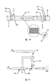
- Figure 11 shows a simplified atomizer for supercooled liquids, the probable main application being the generation of "artificial" snow.
- Figure 12 shows a heat-pump arrangement permitting a very efficient conditioning of water, one application being in fish aquaculture installations.
- the invention provides a simple system for yielding very cold liquid flows, down to temperatures heretofore impossible to attain with any machine. It also discloses improved thermodynamic cycles permitting attaining these low temperatures in a very efficient manner.
- FIG. 1 shows a modified flooded cooler (9) designed according to the present invention. It features double tubesheets (7a, 7b and 7'a, 7'b), the spaces (13, 13') between the latter being filled with insulation, e.g. polyurethane foam, air, etc.
- insulation e.g. polyurethane foam, air, etc.
- the width of that space (13, 13') should be sufficient to provide a good heat barrier, e.g. about 10 to 20 tube diameters (O.D.), or more in special cases.
- Said spaces (13, 13') can also be partly or fully open to atmosphere.
- the improvement here is that the low-velocity liquid in the cooler heads (4), (14), is nowhere in contact with a cold surface (7b, 7'b). Alternate designs will be shown later where the low liquid velocity regions (4a,14b) and/or the cold surfaces themselves are simply eliminated.
- Preventing the cold medium (e.g. refrigerant R) from getting into the spaces (13, 13') between the tubesheets (7a, 7b and 7'a, 7'b) is easy; for example by expanding the tube (10) diameter into said tubesheets by means of an expander.
- Many expansion methods are available (see “Heat Exchangers; Selection, Design and construction", a book by E.A.D. Saunders; John Wiley and Sons, New York).
- FIG. 2 shows another cooler (9) designed according to the present invention. It features two tubeside passes (that is, the fluid goes twice through the shell, e.g. once from left to right, in the lower part of the shell, and back from right to left in the higher part), which reduce the length of said cooler (9) for a given fluid temperature difference between inlet (5) and outlet (6). It also features the above described double tubesheets and smooth fluidtube inlets (3a). An optional baffle (1) is also added for separating the outlet (2) and inlet (3) flows, said baffle extending far enough inside the cooler right-hand head (14) to effectively prevent one fluid flow (2) from disrupting the other (3). A baffle length equivalent to about 10 tube diameters should be sufficient.
- the insulating material (16) could also be installed on the liquid side of the tubesheets, i.e. between the liquid to be cooled and the tubesheet (7a), thus eliminating the cold surface itself.
- tubesheet (7a) could also be actively heated in some way. Although this active heating normally would not be done, it is possible to imagine instances in which it could become desirable, thermodynamically speaking.
- subcooling of the liquid refrigerant from condenser, before its entrance into the expansion device provides improved cycle efficiency. Said subcooling could be performed by sending said liquid refrigerant into the space (13) between tubesheets (7a, 7b). Care should be taken as the final temperature of said subcooled liquid refrigerant should not fall below entering-liquid (5) temperature. This might necessitate the presence of some thermal insulation on the surface of tubesheet (7b), preferably within space (13).
- a cooler (9) like the one in figure 4a, having the proper length and the proper coolant-to-liquid ⁇ T, will give an outlet temperature of 0°C.
- the same cooler (9) would have the capability of providing an outlet temperature of about -3°C. If the liquid were pure water, that outlet temperature would correspond to a supercooled state.
- a liquid is said to be supercooled if it is at a temperature well below the phase-equilibrium temperature while still in the liquid phase.
- the supercooled state is a metastable state. In such a state, a substance has a certain phase stability; but if disturbed, it will try to acquire a greater stability, i.e.
- phase equilibrium temperature e.g. 0°C for pure water
- sources of perturbations mechanical, thermal, etc.
- cooler (9) When fitted with longer conduit extensions (21), cooler (9) will also be capable of delivering said supercooled liquids to a nearby (or remote) reservoir (26) (fig. 4c ).
- Said extensions (21) can be of any length and made out of any convenient material, including plastic.
- Connection (51) between said extension (21) and said extended fluid tube (20) can be of any type, including using soft-plastic unions, e.g. press-fitted in place.
- liquid (5) entering individual tubes in figure 4b will normally come from a distribution chamber located at some distance upstream, said chamber being in any convenient position (e.g. above) relative to shell (9). Said chamber thus replaces the inlet head (4) of cooler (9), being in effect a cooler head (4) separated from shell (9) by a large space (13), said space being completely open to atmosphere.
- the reservoir (26) does not have to be open to atmosphere: the system will work just as well, for example, with reservoir (26) under high inert gas pressure.
- supercooled liquids can be stored in a reservoir (26) almost as easily as any conventional liquid, the only condition being a careful handling (minimum of perturbations). That can be done, for example, by guiding jet(s) of supercooled liquids so that it hits container walls at an angle much smaller than 90° (preferably 30° or less). It is also possible to deliver supercooled liquids to a reservoir through an inlet located below liquid surface. Instead of being stored, supercooled liquids can also be delivered to locations far from the cooler (9), provided said liquids are handled according to the principles given in the present invention.
- figure 5a shows one of several possible designs for a one-tubeside-pass cooler capable of generating supercooled liquids: connectors (31) are used to connect the tube extensions (20), inside the cooler head (14), to the main conduit means (33).
- said connectors (31) can be joined in different ways. For example, they can be glued or soldered to one another, side by side, and press fitted inside an extension (32) of the head (14). Said head (14) could be made in 2 parts one of which could be removed for inspection.
- FIG. 5b shows a 3-tubeside-pass cooler designed according to the present invention, perfectly smooth flow being maintained between inlet (5') and outlet (32) of said cooler (9).
- the 180° elbows (34) in figure 5b could be located inside the shell (9), if desired, instead of inside the heads (4, 14): this, however, would prevent easy cleaning of the inside of conduit means (10).
- said 180° elbows (34) can exhibit relatively sharp turning radiuses. For example, mean radiuses as small as 0,7 times the tube outside diameter have been used successfully.
- figure 5c shows a liquid cooler that can easily be transformed into a liquid "supercooler” of the type shown in figure 5a , said transformation being obtained by the addition of extensions (connectors) (31) to individual liquid conduit-means (20), said extensions (31) then permitting the creation of a large flow in a large conduit means (33). It is also possible to transform the cooler of figure 5c into the "supercooler” of figure 4c by the addition of individual extensions (21) and by the removal of the head (14).
- Said outlet ends or tips (22', 22, 36) are sometimes in a very humid atmosphere, for example in the space above the liquid level inside a reservoir (26). Said outlet ends or tips (22', 22, 36) also tend to be very cold, at about the same temperature as the supercooled liquid. Humidity will thus condense on said cold tips. Being at a temperature below phase equilibrium temperature, the condensed humidity will eventually freeze and ice crystals will touch the flow of supercooled water (23). Ice will then rapidly accumulate on said tips, thus preventing the liquid from flowing. This in turn will provoke freezing inside the conduit means (10).
- the problem can be solved by preventing the freezing of said condensation on said tips (22', 22, 36), or by preventing said condensation itself.
- constructing said tips using certain materials like urethanes helps a lot.
- Depositing on said tips an anti-fogging material can also prevent condensation.
- Another method is simply the local heating of the surfaces of said tips. Said heating can be done by any of the known heating means, using conduction and/or convection and/or radiation as the basic heat-transfer methods. Local surface heating using resistive paper or conductive paints as a heating element is a possibility. Using chemical (exothermic) paints is another.
- Circulation of a warm liquid in a small conduit means (36') at or near the tip (36) of the main conduit means (33) is another possibility (fig. 5a ).
- Simply heating said tips with a flow of warm room air using a small fan was also found to be effective in the case when the reservoir is open to atmosphere. Many other methods could be imagined.
- FIG. 6a shows a coil-in-shell type cooler where the cold medium (R) is inside the shell (9) and the liquid (5) being cooled circulates in the coiled conduit means (10), the top of said shell (9) acting as the tubesheet (7) for said coiled conduit means (10).
- Figure 6b shows an element (60) of a plate type cooler featuring internal channels (61). Both types (fig. 6a, 6b ) can be designed to cool liquids down to and below the freezing point if the fundamental concepts explained above are applied. In both cases, regions of low velocities near cold surfaces have simply been eliminated.
- the plates e.g. roll-bonded aluminium
- the space (62) between plates (60) being used for the circulation of the cold medium
- An example of such a system would be composed of 4 subsystems of equal capacities installed in series, each one being capable of cooling the liquid by about 3°C, this small fluid ⁇ T across each cooler helping in maintaining good efficiency.
- the fluid would enter the lead subsystem at about 12°C, go through each subsystem, one after the other, and leave the lag unit at about 0°C.
- the condenser water would enter the lag unit at, say, 26°C, in turn go through each condenser, and leave the lead unit at 38°C. Since the ⁇ T between the fluid and the refrigerant would be uniformly small, in the CSHE as well as in the HSHE, the overall heat-transfer efficiency would be good and the system COP would be nearer its theoretical maximum.
- the arrangement would also have the advantage that in case of a decrease in the load, one or more of the subsystems could be shut down.
- AHP absorption heat pump
- CHP chemical heat pump
- Figure 7a shows an example of what we could call a hybrid multiple-cascade system, capable of generating very cold liquids (e.g. 0°C water) or supercooled liquids efficiently if large quantities of cheap, low-grade heat are available.
- AHP be arranged in series fashion (along the liquid circuit) with one (or more) VCHP, in order to bring, in two or more steps, the liquid temperature down to its desired low final value.
- one (or more) AHP (or CHP) is also coupled in cascade fashion with one (or more) VCHP heat pump.
- AHP 1 with a capacity of 4 MW (about 1100 tons) is capable of bringing the 12°C water (80), coming from load, down to 6°C (81).
- the cascade subsystem AHP 2 /VCHP 2 (2 MW capacity) is installed in series (in the liquid circuit) with AHP 1 in order to bring water (81) from 6 °C to 3 °C (82).
- AHP 2 would not be capable of bringing the water (81) temperature down from 6°C to 3°C. It is merely used here as a source of cooling water (CW 2 ) at about 6°C for the condenser of VCHP 2 .
- VCHP 3 (2 MW) is capable, with the help of AHP 3 (about 2,2 MW) as a source of cooling water (CW 3 ), of bringing the water (82) to its final temperature of 0°C (83).
- the overall system capacity is 8 MW.
- the sources of power could be: about 12 MW of low grade heat, and about 0,5 MW of mechanical power, assuming a typical COP of 0,75 for the AHPs.
- this mechanical power does not have to be provided by an electric motor; a diesel engine (or any convenient driver) could be used, the fuel being oil, natural gas or any other convenient fuel.
- the above-described cascade arrangements are of course capable of supercooling water and generating either solid ice, snow or ice slurries.
- the system shown in figure 7c is capable of delivering supercooled water at -2°C directly.
- ice could be made during off-peak hours, for later daytime use.
- a night-operation scheme could then look like the one shown in figure 7d; in such a case, the AHP would operate at part load, generating cooling water both for the condenser of said VCHP and for the nighttime (reduced) building load., said building then being cooled using 6°C water
- NARM non-azeotropic refrigerant mixtures
- phase changes are not constant temperature processes; it is thus possible to keep a small and constant ⁇ T between the fluid and the refrigerant.
- the evaporation in the CSHE can induce a 10, 20 or even 30°C temperature increase (or glide). A corresponding decrease in temperature will happen in the HSHE, during condensation.
- the first is that the temperature glide of the refrigerant during phase change be the same as the temperature glide of the fluid, in the evaporator as well as in the condenser.
- the other criterion is that both the evaporator and the condenser be counter-flow heat exchangers.
- the conventional flooded shell-and-tube HX (cooler) is thus inappropriate for such an application.
- the best type of HX for real counterflow heat exchange is the basic double-pipe or tube-in-tube element. For large systems, however, other arrangements have to be found.
- FIG 8 A real counterflow HX suitable both for secondary refrigerants and for non-azeotropic phase-change fluids, and designed according to the present invention, is shown in figure 8 : it is what we might call a one-tubeside-pass "shell-and-multi-double-tube" cooler featuring three tubesheets (7a, 7b, 7c) at each end. It provides full counterflow without presenting any limit to the maximum capacity. It can be built with any convenient number of passes, both on the fluid side and on the refrigerant side. If modified according to the general principles explained above, it can also be used to generate supercooled liquids. A simplified counter-current cooler will be described later. As already mentioned, it is also possible to build counter-current plate-type coolers designed according to the present invention.
- Figure 9a shows an improved VCHP cycle featuring a low-pressure receiver, LPR, acting as a reformer (i.e. a partial distiller), capable of partially separating the components of the NARM: the liquid at the bottom, rich in high-boiling-temperature (less volatile, more dense) component(s) (70) leaves, going towards the pump P and the evaporator EV, while the vapor (71), being rich in the low-boiling-temperature component(s) (more volatile) leaves, going towards the compressor C.
- a fresh flow of partially evaporated refrigerant mixture (72) comes from an overfed evaporator EV, appearing here as a two-shell HX (EV 1 , EV 2 ).
- Said fresh flow (72) provides the reservoir LPR with vapor (71) for the compressor (C) as well as with new liquid (70) for the evaporator, said liquid and vapor having roughly the needed composition.
- Liquid refrigerant also comes at a smaller rate through valve FL from condenser CR (appearing here as a two-part HX, CR 1 and CR 2 ) and high-pressure accumulator HPA.
- the liquid (5) to be chilled flows counter-current to the flow of refrigerant in evaporator EV and leaves at (6).
- Condenser cooling water also flows counter-current to the refrigerant in condenser CR.
- refrigerant mixture is partly dependant on the temperature differential needed in the evaporator, on the fluid side.
- An almost infinite number of NARM can be used.
- Another possibility is the pair R22/R114.
- Many other binary or ternary mixtures are possible.
- the overfeed rate is large, the refrigerant (R) will behave in the cooler (9) almost like a (non-evaporating) highly subcooled fluid.
- the design of the coolers (9) can then be simplified, as will be seen below.
- the pump P is capable of providing us with that large flow. In a way, the cycle is thus similar to the well known liquid-overfeed system, which has many well known advantages: smaller sized components, high system efficiency and well reduced operating costs (ASHRAE Handbook: op. cit.).
- This basic cycle can be modified and/or improved upon in different ways; what is important is the presence here of a reformer LPR which permits sending mixtures of different composition to the hot side and the cold side of the heat pump circuit. How different these compositions will be, depends in a large part upon the overfeed rate through the evaporator. It also depends upon the NARM chosen.
- the denser component can represent more than 75% of the total mass flow in compressor C, but less than 50% in evaporator EV; i.e. the concentration of the dense component can thus go from 1:1 in the evaporator to 3:1 in the compressor (C). The higher the density of the vapor going to the compressor (C), the greater the capacity of the system.
- the capacity of such a system can also be modulated by using methods similar to the ones used in more "conventional" systems.
- the extraction system shown in figure 9b can change the average level of pressure and density in the system, permitting a modulation of the capacity (dayly, weekly or seasonal modulation). This is done by removing from circulation (extracting and temporarily storing) some refrigerant extracted from either one of two points: at or near the condenser exit, for example at the top (73) of the high-pressure receiver HPA; or along the condenser itself, immediately after the point where the desuperheating is complete (about one fourth to one third of the way along the condenser), using separator reservoir SR 1 .
- Vapor at the top of HPA is rich in the low-boiler, volatile, higher-density component(s): removing this vapor from the circuit (via valve V 3 ), by condensing it and storing it in the extraction receiver ER, will give a decrease in system capacity. Extracting the liquid (rich in the high-boiler, non-volatile components) from the bottom of SR 1 (via valve V 2 ) will have the opposite effect.
- the valves V 1 to V 3 which control the extraction process, can be made to respond automatically to a change in demand.
- a subcooler S can be installed: the liquid (75) from condenser CR and/or high pressure accumulator HPA is subcooled by giving up heat to the cold liquid (76) coming from pump P. Said subcooling of said liquid refrigerant (75) can also be obtained by putting it in indirect contact (75) with cool liquid about to enter (5) the cooler EV (fig. 9c ).
- Removing the already vaporized refrigerant at the exit of EV 1 (77) (fig. 9c ) and sending it (78) directly to reformer LPR will also ensure a still larger concentration of non-volatile components in cooler EV 2 and more of the dense vapor at the top of reformer LPR, thus improving cycle capacity and efficiency.
- extracting some liquid from the bottom of SR 2 and sending it to the reformer LPR (via valve V 5 and expansion device CP) will ensure that the mixture entering CR 2 is rich in volatile component(s), thus improving on the heat-transfer properties on the refrigerant side in CR 2 .
- figure 9d shows a cycle featuring a low-pressure reformer LPR, an overfed evaporator EV within a low-pressure circuit L 1 , an overfed condenser CR within a high-pressure circuit L 3 , and, in between, a compression circuit L 2 .
- Said high-pressure circuit L 3 also comprises a high-pressure reformer HPR for partially separating the refrigerant mixture (79) into its components.
- L 1 and L 2 are thus connected via LPR; L 2 and L 3 are connected via HPR.
- Said mixture (79) out of the condenser CR is not completely condensed: its liquid part, poor in dense component(s), will accumulate at the bottom of HPR, from where it will go towards LPR, via expansion device FL; the vapor part in (79), rich in dense component(s), will be re-routed to the condenser CR by the blower B.
- Said blower B is capable of overfeeding said condenser CR, the overfeed rate having any value, including 1.
- Said blower B and said pump P will thus have very similar functions.
- the cycle in figure 9d can also be used with advantage with pure refrigerants or with azeotropic mixtures of refrigerants. In this case, HPR and LPR will simply become liquid-vapor separators. Said overfeeding in CR and/or EV will still be very useful because of its potential for improving system COP and decreasing costs. Said condenser overfeeding can be used independently of said evaporator overfeeding. For example, a condenser overfeeding system would be perfect in an application like the one shown in figure 7b, where calculations show that AHP 2 's evaporator will normally be unable to completely condense the refrigerant circulated in circuit VCHP 2 ; the same thing being said for AHP 3 . More than one of the above-described cycle modifications (fig. 9b to 9d ) could be implemented at the same time, if desired.
- Figure 10 schematically shows a countercurrent cooler designed according to the invention and having one shell-side pass and one tube-side pass.
- the number of liquid conduit means (10) in the shell (9) can be as large as needed.
- such a cooler is capable of providing whatever fluid ⁇ T is needed, assuming the shell (9) is long enough.
- the relative volume-flow rate of vapor generated will be small and the cooler will behave almost like a true countercurrent liquid-to-liquid HX, the closeness of the fluid tubes providing the guiding walls needed by the refrigerant for an orderly countercurrent flow: the tube-in-tube arrangement of figure 8 is thus unnecessary here.
- Still more orderly flow could be obtained with conduit means (10) featuring longitudinal fins.
- Figure 10 shows quite clearly how the mere presence of 2 longitudinal fins per conduit means (10) could provide very good flow guidance as well as improved heat transfer. Of course, many other fin arrangements could be used.
- the cooler (9) of figure 10 could be further improved upon with the installation of a tubesheet (37) made out of a porous material or out of any material providing a small pressure drop, for the purpose of improving the crosswise evenness of the refrigerant flow in the cooler.
- a second porous tubesheet (37') could also be installed in a similar fashion at the other end of the cooler.
- Such a cooler (9) will give the same good results as the one shown in figure 8 , being particularly useful with liquid-overfeed systems and/or with non-azeotropic refrigerants, but with reduced size, complexity and cost.
- the said porous tubesheet (37) could also perform part of the "expansion" of the liquid refrigerant exiting from the hot side of the heat pump.
- Liquid "expansion" from high to low pressure inside the cooler (9) itself could be performed in many other ways.
- one of the fluid conduit means (10) inside said cooler (9) could be replaced by a capillary tube extending between tubesheet 7'b and tubesheet 7b; the liquid refrigerant under pressure would, for example, enter space 13', where it would be partly subcooled, go through said capillary tube while being cooled (countercurrent) by neighbouring evaporating refrigerant mixture R.
- said liquid refrigerant After going through cooler EV, said liquid refrigerant would have a reduced pressure and would be sent directly to reservoir LPR (valve FL then being superfluous).
- the single shell of cooler (9) in figure 10 would have to be quite long. Its length could be cut in half by installing two shorter shells in series. Building each one of said shorter shells with two shell-side passes and two tube-side passes would further reduce the length of said shorter shells for a given fluid ⁇ T. Many such combinations could be imagined.
- the counterflow cooler (9) of figure 10 and all of its possible adaptations can be made to handle supercooled liquids by applying the general principles explained above.
- the high efficiency chiller has obvious applications in the field of space cooling. It also has many other applications in very diversified fields. Following are more details on some of these applications.
- the liquid chillers described above can be used in a large number of cooling applications, especially space cooling.
- the (SUPERPAC) full-range chiller can be installed in series with a conventional chiller to obtain water at any temperature between 6°C and 0°C (using one SUPERPAC unit or, preferably, two SUPERPAC units in series, for better efficiency).
- a final temperature of 0°C would give an increase in system capacity of more than 100% without any change in the size of the main chilled-water line.
- another cooler capable of generating supercooled water can be installed in series: when sent to a reservoir, this supercooled water can be made to partially change phase: the ice crystals are accumulated while the liquid is recirculated to obtain more ice.
- the floating ice crystals can be used for short or long term energy storage.
- the water at the bottom of the reservoir can be circulated in the building and used as the energy transport fluid.
- the slurry itself can also be used as the energy transport fluid.
- the lag unit used normally for generating very cold water, e.g. at 0°C
- this ice could be used to shave the peak load, while said lag unit would come back to its normal use, e.g. the cooling of water from 3°C to 0°C.
- CSHE inlet temperatures 6°C (or more)
- oulet temperatures 6°C directly, within the same cooler, at the expense of efficiency, however.
- the crystallization of supercooled liquids can be obtained by a mechanical or thermal perturbation; for example, an abrupt change in direction, a vibration of any frequency (e.g. from a sonic or ultrasonic generator); by a cooling element (e.g. of the thermo-electric type) touching the liquid (e.g. partly under and partly above liquid level), etc.; or by seeding the supercooled liquid with ice crystal or a piece of ice obtained elsewhere.
- a mechanical or thermal perturbation for example, an abrupt change in direction, a vibration of any frequency (e.g. from a sonic or ultrasonic generator); by a cooling element (e.g. of the thermo-electric type) touching the liquid (e.g. partly under and partly above liquid level), etc.; or by seeding the supercooled liquid with ice crystal or a piece of ice obtained elsewhere.
- the ice slurry accumulating in the reservoir is probably the ideal energy transport fluid, in new installations as well as in retrofit situations: at the proper solids concentration (e.g. 20%), it will circulate in pipes, pumps and heat exchangers. Its energy absorption capability being more than 4 times that of liquid water at 6°C, mass flows in main lines will be 4 times less, pumping power will be about 5 times less, line diameters about 50% smaller, etc.
- Different storage strategies can be utilized depending on the application, the main advantage always being that pure water can be used instead of solutions containing glycol or other environmentally sensitive freezing-point depressants.
- additives can be added to the slurry to further improve its characteristics: anti-friction and anti-corrosion additives, dispersants that will prevent the agglomeration of the crystals, etc.
- the coolers constructed according to the present invention can also be used as CSHE for liquid-source heat pumps, using conventional cycles as well as the new improved cycles described above.
- a CSHE design such as the one in fig. 1
- water cooled to about 2°C or 3°C can be used as a source of heat, for space heating as well as for many other uses.
- the temperature of the source can be as low as 0°C. This cannot be done with other types of CSHE now on the market.
- CSHE designs such as the ones shown in fig. 4, 5, etc., liquids at the freezing point (e.g. from a lake, during the winter period) can be used as a heat source.
- the supercooled water coming out of the machine is simply returned to the large body of water where it will tend, being lighter than water at 4 °C (and at 0 °C), to rise to the surface and mix with the ambiant water; if ice is generated by this mixing process, it will tend to float on the surface.
- Such heat pumps can be used for space heating. They can also be used in many special situations, e.g. snow-melting plants, mine heating systems, etc.
- the method used for delivering said supercooled liquid into droplet form the basic parameter being the fact that the snow is made here from liquid previously cooled or supercooled by a machine.
- the basic parameter being the fact that the snow is made here from liquid previously cooled or supercooled by a machine.
- the turbulence generated by the friction between air and said water is capable of changing the stream of supercooled water into a multitude of supercooled droplets: said changing of the type of stream is a disturbance capable of initiating the phase-change process of the metastable droplets.
- the droplets travel through cold air at high speed, they lose heat (by convection and evaporation) and thus continue to grow into full size snowflakes.
- Such a snow-making process does not need compressed air and is therefore very energy efficient.
- the atomizer shown in figure 11 is also capable of generating very small droplets: supercooled liquid (90) flows out of a conduit (91) as a thin, wide film (93); compressed air (94) going through tube (95) and through a nozzle (96) provides a high-speed jet of air.
- said jet can be subsonic, sonic or supersonic.
- a well designed nozzle will produce an almost isentropic expansion; the result will be a very cold, high-speed air jet requiring relatively small upstream pressures, thus saving some energy.
- Said air jet is then blown through said thin liquid film (93) of supercooled liquid, changing the film flow into a small droplet flow (97).
- tip (92) of said tube (91) must be modified (e.g. said tip being heated) for reliable operation.
- the partly frozen droplets generated by an atomizer are very small in size, like the ones generated by an atomizer similar to that of figure 11 , they can also be used as seeders for larger droplets of cold liquid generated by more conventional methods: when the small dendritic crystal touches a larger drop of liquid which has been pre-cooled, e.g. by ambiant air, it provokes, in said larger drop, the beginning of the phase-change process.
- the air and water jets do not have to be at right angle to one another; they can be at any angle, including parallel. They can be side by side or concentric, the jet at the center being either the air jet or the supercooled-water jet. Both jets can be of any shape, e.g. circular, annular, etc.
- the air jet is used mainly for changing the liquid stream into droplets (due to the action of turbulence) but also for accelerating the cooling process, and thus the speed of the phase change.
- the supercooled water necessary for generating snow can sometimes be obtained (weather permitting) simply by circulating cold water in a properly designed air-to-water HX (v.g. a pipe loop or a plate HX located above ground in cold ambiant air).
- a properly designed air-to-water HX v.g. a pipe loop or a plate HX located above ground in cold ambiant air.
- HX would have to be designed according to the invention.
- Water being used for generating snow normally arrives at the snow-making machine at a temperature approaching 1°C. But in certain weather conditions and/or at certain times of the year, approaching water can be at a temperature as high as 5°C or more. In order to be able to manufacture high quality snow, it is then preferable to precool said approaching water down to 1°C or below with a full-range chiller, i.e. with the invention, even when using conventional snow-making machines down the line.
- ambiant air for providing further cooling of water droplets and/or for completing the phase change process
- a flow of colder air could be used, said colder air having been cooled by some type of HX, e.g. the CSHE of a refrigerating system, or some other device. It would then be possible to generate snow in difficult weather conditions, e.g. when the wet-bulb temperature of the ambiant air is at or slightly above 0°C.
- the supercooled water jets can be made to crystallize on a plate, a piece of screen or any other type of support located above the liquid surface of the reservoir; after the desired thickness of crystals has accumulated on said support (say, 50 cm or 1 m), said support and crystals are removed from underneath said jets of supercooled water and liquid water remaining between crystals is left to drain for a few minutes.
- the result again is high quality snow. If said support were a slowly-moving conveyor belt, the handling of said snow would be easier, especially when large quantities of snow are needed. The quality of this snow can be further improved by removing the small amount of humidity still remaining between crystals. Different methods exist to perform this removal. Centrifugal action is one.
- a high-capacity machine fitted with a large reservoir would be capable of generating enough snow to cover a ski slope. Skiing during summertime thus becomes possible.
- the snow on the ground will last longer if insulation (preferably porous) was installed below the snow cover. Or said ground could be kept cold artificially with an underground refrigerating system. This type of high-quality snow can also be used for many other purposes.
- Freeze concentration (FC) applications are divided into two categories.
- the desired product is the solvent and the degree of concentration is low because the concentrate is easily disposed of.
- Water desalination is an example: the concentrate (e.g. 50% or more of the original solution) is discharged back into the sea.
- the desired product is the concentrate.
- a relatively high concentration is needed; what is disposed of is the solvent. Examples are the concentration of acids, alkali, milk, salts, coffee extract, etc.
- the ice crystals formed from a supercooled aqueous liquid flow are absolutely pure solid water. Supercooling can thus become the basic process in a new freeze concentration method.
- An example is that of obtaining potable water from polluted water. When separated from the original solution, washed clean and melted, the crystals become pure water.
- the separation process can be very simple: indeed, crystallization and separation can be made in a single operation. For example, sending a jet of supercooled water (from a reservoir or directly from a cooler) onto a conveyor belt (made of any convenient material, including thin perforated sheet metal) creates a mechanical shock which will initiate the crystalization process, the crystals remaining on the belt while the liquid is drained back into the reservoir. The accumulated crystals can then be moved elsewhere (v.g. into a wash column) by the belt.
- Other crystallization methods are possible, including vibrations from a sonic or an ultrasonic generator.
- Other separation methods are possible, including centrifugation.
- the cleaning of crystals can be done in wash columns. This is a relatively mature technology and two types of systems are used: the gravity column and the pressurized column.
- the former is very tall, the height thus being sufficient to squeeze the ice bed, helping in the final cleaning process, which is done by introducing wash liquid at the top of the column. Said wash liquid is obtained from melted pure crystals.
- pressurized columns hydraulic pressure forces the wash liquid to flow down.
- An important advantage of the invention in FC applications is the fact that by modifying the operating conditions, the crystal size can easily be changed.
- "Deeply" supercooled liquids e.g. -1,5°C water
- slightly supercooled liquids e.g. -0,5°C water
- blocks of pure ice having a mass of several kg have even been obtained during experiments with supercooled water at -0,5°C.
- Such blocks are obviously very easy to clean, without the expense of wash columns.
- Different installations can be imagined permitting the fabrication of much larger blocks of pure ice. For example, one can imagine that a large flow of supercooled water at -0,5°C has been generated; directing one or more jets of such water along a large plate will permit hard ice to build up to unlimited thicknesses on the plate.
- the plate In such an installation, it would be better (but not necessary) for the plate to be slightly cooled by some type of cooling system for two reasons. First, it would be easier to induce crystallization at the beginning of the process (crystallization of 0,5 °C water is relatively difficult to induce; but once started, it is self propagating); second, it would prevent the ice from slipping away from the plate, which would preferably be slanted a few degrees from a horizontal position to facilitate the draining of the liquid. Temporarily stopping the plate-cooling process would permit the block of ice to slip and be transported to a nearby reservoir where it could be melted. The entire process could easily be automated. It is important to realize here that the slight cooling of the said plate is not performed for freezing the supercooled water but to help in the handling process.
- the invention also provides another interesting solid/liquid separation process. It works like this. As said earlier, supercooled liquids can be stored in reservoirs. Moreover, if supercooling is to be obtained at the cooler (9) exit (5), crystals (24) should be prevented from entering the liquid cooler (9), e.g. by using a filter (52) (fig. 4c ), as said in a previous patent, (op. cit.). Simple cotton filters (pieces of old bed sheets covering a perforated 40 cm length of 5 cm diameter pipingl) have been used successfully for this purpose. When crystallization is not provoked (26), the bulk of the liquid (25) slowly becomes supercooled inside said reservoir (26); ice then starts to build up all over said filter (52), said filter (52) acting as a crystallizer.
- Said ice is relatively porous, so that liquid (5) keeps flowing towards pump P: ice thicknesses of up to 3 cm have been obtained over said filter. Also, said ice is relatively hard and quite easy to remove by hand from around said filter (52). Said ice being easy to wash clean, this phenomenon can be used as the basis for a simple freeze concentration method.
- the "filter” does not have to be installed as in figure 4c ; and it can have any shape; be made of any material; it could be the whole bottom of said reservoir (26); or it could be its side walls; or a large perforated plate located anywhere inside the reservoir (26), the liquid (25) being sucked from both sides of said plate. The harvesting of the resulting ice can easily be automated.
- Melting of ice crystals can be done with the energy from any source, including that from the HSHE of the machine; or with the energy from a building to be air conditioned: one then has a dual-purpose system capable of purifying polluted water (or desalinating sea water, or treating waste water, e.g. industrial) and cooling a building. Other dual-purpose systems could be imagined.
- the heat pump circuit will usually be of the VCHP type, and the type of evaporator used will be any of those described above. In this system, however, most of said heating is performed in a passive way by using a liquid-liquid HX, the remainder of the heating being performed by the HSHE of the heat pump, said heat pump also having a CSHE, said CSHE being capable, when necessary, to supercool said rejected liquid.
- Fresh water (101) is drawn say from a river (100) at 0°C and sent (102) by a pump P1 through HX, where heat is absorbed. Said fresh water thus comes out (103) of HX at, say, 12 °C and goes through the HSHE where its temperature is again increased to about 14,5°C. Said fresh water (104) then enters the fish tank (105). Some evaporation exists over said tank (105) and the gray water coming out (106) of said tank (105) is at a temperature of about 14°C.
- Another pump P2 sends said gray water (107) through HX, where it gives its heat to incoming fresh water (102). Said grey water then goes (108) through said CSHE, where it loses the remainder of its energy: said gray water comes out (109) of said CSHE at a temperature of about 0°C and is sent back into the river (100).
- the above-described system of figure 12a needs a CSHE capable of supercooling water. Indeed, when said system is started up in wintertime, circulating pumps P1 and P2 are first switched on: the temperatures are then uniform at 0°C. When the heat-pump circuit is started, the water then entering (108) the CSHE is at 0°C and will remain so for a considerable length of time. The water coming out (109) of the CSHE will thus be supercooled to about -2°C. As the temperature in said tank (105) slowly increases to 14°C, the temperature at point 108 will slowly increase to 2°C and the temperature at point 109 will slowly increase to 0°C.
- Cold or supercooled water from a full-range chiller can be used in the fishing industry. In fishing boats, it will keep the fish fresh, these being sprayed directly with said cold or supercooled water. In the case of a supercooled water spray, some ice crystals will normally form on and around the fish. In the fish plant, said water can be used for washing the fish. Said water can also be sprayed onto the fish before or after it is prepared by the workers to make sure that it stays cold and fresh.
- Said cold or supercooled water (or the ice slurry formed with the latter) can also be used for the mixing of concrete. Indeed, problems arise during the construction of dams, bridges, etc., because of the heat generated during the hardening of the thick concrete.
- a solution is the mixing of the concrete using very cold water, supercooled water or an ice slurry, all of which can be obtained with the above-described technology.
- the new cooler designs presented above have often been described as parts of VCHP systems. Absorption and chemical heat pump systems were also briefly mentioned. It is worth mentioning that the new cooler designs can be used, if desired, within any of the known (and future) heat pumping cycles; even as part of far-fetched cooling "cycles" like the sound-wave cooling method. Two or more very different cycles can even be used in a cascade arrangement.
- the phase of the cold medium used in the cooler e.g. liquid, gas
- the method of circulation of the refrigerant in the cooler e.g spray type, overfeed type, etc.
- liquid refrigerant used in the system there is no limitation as to the type of liquid refrigerant used in the system: primary (halocarbons, etc.) or secondary (e.g. brine, etc).
- number of components in the liquid refrigerant single component refrigerants or multi-component mixtures of refrigerants can be used.
- type of liquid chilled or supercooled acids, alkalis, coffee extracts, water, etc.
- ice crystal it can actually be a crystal made out of any liquid, e.g. pivalic acid crystalizing from a methanol solution.
- water is mentioned in the above text, there is no limitation as to the purity of said water.
- cooler design can also be applied to practically any cooler type, even to the very unusual: plate type, coil in shell, flooded shell-and-tube, shell-and-multi-double-tube, etc. All of these can be designed according to the general principles outlined above.
- position of the cooler e.g. horizontal or vertical.
- the counter-flow HXs described in this invention are not only for using with non-azeotropic refrigerants.
- tubesheet is mentioned in the text, there is no limitation as to the number and type of "tubes" going through said tubesheets.
- conduit means there is no limitation as to the material used for making the conduit means and/or the shell and/or parts thereof: metals, plastics, etc.
- shape of the conduit-means cross-section circular, oval, flattened, etc.
- Said conduit means can be provided with internal and/or external fins.
- the exact fin size, shape, number and arrangement except that in the case of supercooled liquid flows, the internal fins should respect the general principles stated in the invention, e.g. smooth flow, etc.
- fluid velocity and pressure inside said conduit means velocities and pressures compatible with common HX design practice are acceptable.
- the exiting fluid can be partly changed to ice; there is no limitation as to the method of crystallization: any mechanical or thermal perturbation can be used, including vibrations, etc. Seeding with a crystal or a block of ice is another method.
- the type of solid-liquid separation method conveyor belts, gravity draining, centrifugal drives, etc.
- the type of ice generated depending on operating conditions, soft and fragile dendritic ice as well as hard ice can be obtained.
- the method of preventing ice from forming at the outlet of supercooled liquid conduits if local heating is used, above or below liquid level, there is no limitation as to the heat transfer method used for heating: conduction, convection or radiation.
- Coolers built according to the present invention do not have to be used within any particular heat-pumping cycle.
- said coolers can be used to obtain very cold or supercooled liquids or an ice slurry without using any thermodynamic cycle; for example, said cooler can be simply an air-to-liquid HX, said air being ambiant air.
- Other arrangements could be imagined.
- SUPERPAC which stands for "SUPER Pompe A Chaleur.
- the chiller capable of generating supercooled liquids will be called a SUPERCHILLER and its evaporator will be called a SUPERCOOLER.
- Supercooled water generated with said invention will be called SUPER WATER. Ice obtained from a supercooled aqueous liquid will be called SUPER ICE. Snow obtained from the invention will be called SUPER SNOW.
- the thermodynamic cycles of figure 9 will be called SUPER CYCLES, even when said cycles are not being used to produce supercooled liquids.
Landscapes
- Engineering & Computer Science (AREA)
- Physics & Mathematics (AREA)
- Thermal Sciences (AREA)
- Mechanical Engineering (AREA)
- General Engineering & Computer Science (AREA)
- Combustion & Propulsion (AREA)
- Chemical & Material Sciences (AREA)
- Sorption Type Refrigeration Machines (AREA)
- Heat-Exchange Devices With Radiators And Conduit Assemblies (AREA)
- Physical Or Chemical Processes And Apparatus (AREA)
- Separation By Low-Temperature Treatments (AREA)
- Thermally Insulated Containers For Foods (AREA)
- Details Of Measuring And Other Instruments (AREA)
- Other Air-Conditioning Systems (AREA)
Claims (34)
- Ein System zum Kühlen von Flüssigkeiten bestehend aus:wobei jedes der genannten oder anderer Kühlerenden von dem Kältemittel (R) durch ein Paar von doppelten Rohrböden an beiden Enden (7a, 7b, 7'a, 7'b) getrennt ist, zwischen welchen sich jeweils ein Abstand befindet und durch welche die Leitung oder Leitungen (10) durchlaufen, wobei jeder der doppelten Rohrböden (7a, 7b und 7'a, 7'b) jeweils aus einem inneren Rohrboden (7b, 7'b) und einem äußeren Rohrboden (7a, 7'a) besteht welcher letztere verhindert, daß die Flüssigkeit (5) innerhalb der Kopfteile (4, 14), in welchen die Flüssigkeit stagniert oder eine, im Vergleich zur Durchschnittsgeschwindigkeit innerhalb der den Kühler (9) durchlaufenden Rohre (10), niedrige Geschwindigkeit besitzt, die kalten inneren Rohrböden (7b, 7'b) berührt.Einem Kühler (9) welcher ein Kältemittel (R) enthält, der genannte Kühler (9) versehen mit einem Einlaßkopfstück mit einem Einlaß (5'), durch welchen eine zu kühlende Flüssigkeit (5) einströmt, wobei der genannte Kühler ebenfalls ein Auslaßkopfstück mit einem Auslaß (6') besitzt, durch welchen die innerhalb des Kühlers (9) gekühlte Flüssigkeit (6) austritt undmindestens einer Leitung (10) innerhalb des Kühlers (9) welche von der zu kühlenden Flüssigkeit (5) durchströmt wird und dies mit einer durchschnittlichen Geschwindigkeit, nötig um durch das Kühlmittel (R) abgekühlt zu werden, wobei die genannte Leitung, oder jede beliebige andere Anzahl von Leitungen (10), geradlinig oder glatt gekrümmt ist und durch den Kühler (9) zwischen einem Kopfteile (4) am Einlaßende und einem anderen Kopfteile (14) am Auslaßende des genannten Kühlers (9) verläuft, wobei das genannte Kopfteil (4) als Verteiler (4a) für die Flüssigkeit (5) wirkt welche durch den Einlaß (5) eintritt während das andere Kopfteil (14) als Empfänger (14b) für die Flüssigkeit (2) wirkt welche die Rohrleitung oder Rohrleitungen (10) durchströmt hat,
- Ein System zum Kühlen von Flüssigkeiten nach Anspruch 1, bei welchem der genannte Kühler (9) zusätzlich einen Kältemitteleinlaß (8) besitzt durch welchen das Kältemittel (R) dem Kühler zuströmt, sowie einen Kältemittelauslaß (11) durch welchen das Kältemittel (R) ausströmt, wobei die Anbringung des genannten Kältemitteleinlasses (8) nahe dem Auslaßende ist durch welches die gekühlte Flüssigkeit (6) austritt, sowie die Anbringung des Kältemittelauslasses (11) nahe dem erwähnten Einlaßende durch welches die zu kühlende Flüssigkeit eintritt,wobei bei diesem Kühler (9) die erwähnten Rohrleitungen (10) mit mindestens zwei Längsrippen (10') zwischen den Positionen 37 und 37' versehen sind und diese Positionen 37 und 37' zwischen den erwähnten Doppelrohrböden (7a, 7b und 7'a, 7'b) derart angeordnet sind, daß eine der genannten Positionen (37) nahe dem erwähnten Doppelrohrboden (7a, 7b) am Einlaßkopfteil (4) des Kühlers (9) liegt, die andere (37') der genannten Positionen (37, 37') nahe dem erwähnten Doppelrohrboden (7'a, 7'b) am Auslaßkopfteil (14) des Kühlers (9) liegt,wobei die jeweiligen Längsrippen (10') der erwähnten Rohrleitung oder Rohrleitungen (10) einen oder mehrere Strömungskanäle formen durch welche das Kühlmittel (R) im Gegenstrom zu der zu kühlenden Flüssigkeit, welche die Rohrleitung(en) (10) durchfließt, strömt,derart, daß der Raum zwischen der einen (37) der erwähnten Positionen (37, 37') und dem nächstgelegenen Rohrboden (7b) einen Strömungempfänger für das Kältemittel (R) formt, welches die erwähnten Strömungskanäle durchflossen hat und welches dann den Kühler (9) durch den erwähnten Kältemittelauslaß (11) verläßt,während der Raum zwischen der anderen (37') der erwähnten Positionen (37, 37') und dem nächstgelegenen Rohrboden (7'b) einen Strömungverteiler für das Kältemittel (R) formt, welches durch den erwähnten Kältemitteleinlaß (8) in den Kühler (9) eintritt und so auf die erwähnten Strömungskanäle verteilt wird,all dieses dazu führend, daß der erwähnte Kühler (9) auf diese Weise in einen Kühler verwandelt wird welcher zum wahren Gegenstromwärmeaustausch fähig ist.
- Ein System zum Kühlen von Flüssigkeiten nach Anspruch 1, bei welchem der genannte Kühler (9) zusätzlich einen Kältemitteleinlaß (8) besitzt durch welchen das Kältemittel (R) dem Kühler zuströmt, sowie einen Kältemittelauslaß (11) durch welchen das Kältemittel (R) ausströmt, wobei die Anbringung des genannten Kältemitteleinlasses (8) nahe dem Auslaßende ist, durch welches die gekühlte Flüssigkeit (6) austritt, sowie die Anbringung des Kältemittelauslasses (11) nahe dem erwähnten Einlaßende durch welches die zu kühlende Flüssigkeit eintritt, wobei der erwähnte Kühler (9) mit einem zusätzlichen Paar von Rohrböden (7c, 7'c) versehen ist welche innerhalb der erwähnten Doppelrohrböden (7a, 7b und 7'a, 7'b) so angebracht sind, daß einer (7c) der erwähnten zusätzlichen Rohrböden (7c, 7'c) in der Nähe des Doppelrohrbodens (7a, 7b) am Einlaßkopfstück (4), der andere (7'c) in der Nähe des Doppelrohrbodens (7'a, 7'b) am Auslaßkopfstück (14) angebracht ist,wobei in dem erwähnten Kühler (9) jede Leitung (10) von einem größeren Rohr (30) umgeben welches von dem einen (7c) der erwähnten Zusatzrohrböden (7c, 7'c) zu dem anderen (7'c) reicht,wobei der Zwischenraum zwischen der genannten inneren Leitung (10) und dem äußeren Rohr als Leitung dient durch welche das Kältemittel (R) in Gegenstrom zu der zu kühlenden Flüssigkeit (5), welche die Rohrleitung(en) (10) durchströmt, hindurchfließt undder Zwischenraum (41') zwischen dem neuen Rohrboden (7'c) und dem benachbarten Rohrboden (7'b) zum Verteilen des Kältemittels (R) dient nach seinem Eintritt (8) in den genannten Kühler (9) undder Zwischenraum (41) zwischen dem neuen Rohrboden (7c) und dem benachbarten Rohrboden (7b) als Empfänger des Kältemittels (R) dient vor seinem Austritt (11) aus dem genannten Kühler (9), welcher dadurch in einen Doppelrohrkühler umgewandelt wird, für echten Gegenstromwärmeaustausch geeignet.
- Ein System zum Kühlen von Flüssigkeiten nach Anspruch 3 in welchem das Kühlmittel von der Art einer nicht-azeotropischen Mischung ist und das genannte Kühlsystem als Wärmepumpe ausgeführt ist, mit einer Heißseite und einer Kaltseite, welche letztere den genannten Kühler (9) enthält sowie einen Niederdruckreformer (LPR) wobei dieser Reformer ein Reservoir ist welches das genannte Kältemittel in flüssiger oder gasförmiger Phase enthalten kann,wobei der Dampf den oberen Teil des Reformers, die flüssige Phase den unteren Teil des Reformers füllt,wobei der Dampf oben am Reformer entnommen, verdichtet, kondensiert und auf der warmen Seite des genannten Kreislaufes entspannt wird, wobei der genannte Kühlmitteldampf an mehr flüchtigen, dichteren Bestandteilen der Mischung angereichert ist,wobei die Flüssigkeit unten am Reformer (LPR) entnommen, zirkuliert und auf der kalten Seite des genannten Wärmepumpenkreislaufes verdampft wird, wobei das flüssige Kühlmittel an weniger flüchtigen Bestandteilen der genannten Mischung mit höherer Verdampfungswärme angereichert ist und die Zirkulation auf der genannten kalten Seite durch eine Kühlmittelumlaufpumpe P erzeugt wird welche imstande ist den genannten Kühler zu überspeisen.
- Ein System zum Kühlen von Flüssigkeiten nach Anspruch 4 bei welchem die Kondensierung des erwähnten Kältemittels in der Warmseite in einem überspeisten Verflüssiger (CR) erfolgt, wobei das erwähnte Kühlsystem aus drei verbundenen Kreisläufen besteht,wobei der erste der genannten Kreisläufe ein Niederdruckkreislauf (L1) ist welcher den erwähnten Kühler, die erwähnte Kühlmittelumlaufpumpe (P) und den erwähnten Niederdruckreformer (LPR) enthält,der dritte der genannten Kreisläufe ein Hochdruckkreislauf (L3) ist welcher ein Gebläse (B), den erwähnten überspeisten Verflüssiger (CR) sowie einen Hochdruckreformer (HPR) enthält, wobei dieser Hochdruckreformer ein Reservoir ist welches das genannte Kältemittel in flüssiger oder gasförmiger Phase enthalten kann undder zweite (L2) der genannten verbundenen Kreisläufe den ersten (L1) mit dem dritten (L3) verbindet und den erwähnten Niederdruckreformer (LPR), einen Verdichter (C), den erwähnten Hochdruckreformer (HPR) sowie eine Expansionsvorichtung (FL) enthält,wobei das erwähnte Gebläse (B) den Verflüssiger (CR) so überspeisen kann, daß das aus ihm austretende Kältemittel (79) aus einer flüssigen und einer gasförmigen Phase besteht, wobei sich die genannte flüssige Phase im unteren Teil des erwähnten Hochdruckreformers (HPR) ansammelt, die gasförmige Phase dagegen in dem oberen Teil des Hochdruckreformers (HPR),wobei die erwähnte gasförmige Phase durch das Gebläse (B) wieder in den Verflüssiger (CR) zurückgeführt wird und die erwähnte flüssige Phase über die Expansionsvorichtung (FL) dem Niederdruckreformer (LPR) zugeführt wird, wobei der genannte Hochdruckreformer (HPR) auch durch den Verdichter (C) mit Kältemitteldampf gespeist wird,so daß das System dadurch gekennzeichnet ist, daß es zu einer teilweisen Trennung der mehr oder weniger flüchtigen Bestandteile einer nicht-azeotropischen Kältemischung imstande ist, wobei der Dampf, reich an flüchtigen Bestandteilen größerer Dichte, in den Hochdruckkreislauf L3 zurückläuft, was zu einer verbesserten Wärmeübergangszahl im Verflüssiger CR führt, während die Flüssigkeit, mit weniger flüchtigen Bestandteilen angereichert, über die Expansionsvorichtung (FL) in den Niederdruckreformer LPR geführt wird.
- Ein System zum Kühlen von Flüssigkeiten nach Anspruch 3 bei welchem das erwähnte Einlaßkopfteil sowie das erwähnte Auslaßkopfteil des Kühlers (9) so ausgebildet sind, daß dieser Kühler ein rohrseitiger Mehrfachdurchlaufkühler wird, wobei die zu kühlende Flüssigkeit (5) den Kühler (9) mehrfach durchlaufen kann.
- Ein System zum Kühlen von Flüssigkeiten nach Anspruch 3 bei welchem der genannte Kühler (9) den kaltseitigen Wärmetauscher einer Wärmepumpe bildet, wobei die der Flüssigkeit (23) entzogene Energie der Warmseite der Wärmepumpe zugeführt wird wo sie abgegeben wird und zu Heizzwecken benützt werden kann.
- Ein System zum Kühlen von Flüssigkeiten nach Anspruch 3 bei welchem die Leitung oder Leitungen (10) des erwähnten Kühlers (9) jeweils mit Verlängerungen (20, 21) versehen sind, sodaß diese Leitung(en) (10) des genannten Kühlers (9) über den Rohrboden (7'a) des erwähnten Doppelrohrbodens (7'a, 7'b) hinausreichen und der Deckel des Kopfteiles (14) überflüssig wird,wobei die Flüssigkeit (23), die dem erwähnten Kühler (9) entströmt, einem Ort wo sie gebraucht wird durch die genannten individuellen Verlängerungen (20, 21) zugeführt wird, wobei diese individuellen Verlängerungen (20, 21) Totwasserzonen und Gebiete mit Fließgeschwindigkeiten unterhalb der Durchschnittsgeschwindigkeit vermeiden wodurch der innere Rohrboden (7'b) des Doppelrohrbodens (7'a, 7'b) am genannten Austrittsende des Kühlers (9) unnötig wird,während die äußeren Oberflächen der Enden (22, 22') der individuellen Verlängerungen (20, 21) aus denen die genannte gekühlte Flüssigkeit (23) austritt durch ein Material gebildet werden welches Kondensation verhindert und/oder irgendwie geheizt werden, sodaß die Bildung von Eiskristallen and den genannten Enden (22, 22'), welche kälter als die Umgebung sind, verhindert wird undder genannte Kühler (9) dadurch fähig wird eine Flüssigkeit auf sichere Weise bis auf eine Temperatur unterhalb der Flüssig/Fest-Gleichgewichtstemperatur abzukühlen, ohne daß die Leitungen zufrieren, sodaß die genannte Flüssigkeit (5) also dadurch in eine unterkühlte Flüssigkeit (23) verwandelt wird und der genannte Kühler (9) zum Unterkühler wird sowie das genannte Kühlsystem zum Tiefkühlsystem wird.
- Ein System zum Kühlen von Flüssigkeiten nach Anspruch 8 bei welchem der genannte Kühler (9) den kaltseitigen Wärmetauscher einer Wärmepumpe bildet, wobei die der Flüssigkeit (23) entzogene Energie der Warmseite der Wärmepumpe zugeführt wird wo sie abgegeben wird und zu Heizzwecken benützt werden kann und die genannte Wärmepumpe dadurch befähigt wird als Energiequelle Flüssigkeiten an der Flüssig/Fest-Gleichgewichtstemperatur zu verwenden.
- Ein System zum Kühlen von Flüssigkeiten nach Anspruch 8 bei welchem die genannte, dem Kühler (9) austretende Flüssigkeit (23) zum teilweisen Phasenwechsel angeregt wird, welcher dann eine Mischung aus Eis (24) und kalter Flüssigkeit (25) bei der Phasengleichgewichtstemperatur liefert,
wobei die Eiskristalle angesammelt werden (z.B. in einem Behälter (26)) bis das gewünschte Verhältnis von fester zu flüssiger Materie erreicht ist, wobei die Mischung mit Hilfe einer Mischvorrichtung jeglicher Art homogen und in stetiger Bewegung gehalten wird, so daß der entstehende Matsch dann einfach zu anderen Orten gepumpt werden kann. - Ein System zum Kühlen von Flüssigkeiten nach Anspruch 1 in welchem die genannten Rohrböden (7a, 7b) am erwähnten Einlaßende des Kühlers (9) weit genug von einander entfernt sind um eine Wärmebarriere zu bilden zwischen der genannten Flüssigkeit (5) innerhalb des erwähnten Kopfteiles (4) und dem erwähnten Kältemittel (R), wobei der Zwischenraum (13) zwischen den genannten Rohrböden (7a, 7b) mit irgend einem isolierenden Material gefüllt ist,
wobei die genannten Rohrböden (7'a, 7'b) am erwähnten Auslaßende des Kühlers (9) weit genug von einander entfernt sind um eine Wärmebarriere zu bilden zwischen der genannten Flüssigkeit (5) innerhalb des erwähnten Kopfteiles (14) und dem erwähnten Kältemittel (R), wobei der Zwischenraum (13') zwischen den genannten Rohrböden (7'a, 7'b) ebenfalls mit irgend einem isolierenden Material gefüllt ist. - Ein System zum Kühlen von Flüssigkeiten nach Anspruch 11 in welchem die erwähnte, durch die genannten Doppelrohrböden (7a, 7b und/oder 7'a, 7'b) gebildete Wärmebarriere durch die Anwesenheit eines steifen Stückes (16) aus Isoliermaterial gebildet wird welches an dem äußeren (7a und/oder 7'a) der Doppelrohrböden (7a, 7b und/oder 7'a, 7'b) befestigt wird und dadurch die inneren (7b und/oder 7'b) Rohrböden der Doppelrohrböden (7a, 7b und/oder 7'a, 7'b) unötig macht.
- Ein System zum Kühlen von Flüssigkeiten nach Anspruch 1 bei welchem die genannten (mindestens eine) einzelnen Leitungen (10) des Kühlers (9) mit individuellen Verlängerungen (35) versehen sind, sodaß die Leitungen (10) des genannten Kühlers (9) über den Rohrboden (7a) des erwähnten Doppelrohrbodens am Einlaßende hinausragen, sodaß diese Verlängerungen (35) das individuelle Speisen der Leitungen (10) mit Hilfe eines einige Entfernung stromauf des Kühlers (9) gelegenen Verteilers erlauben, wobei diese Verlängerungen (35) mit dem genannten Verteiler Gebiete niedriger Strömungsgeschwindigkeit in der Nähe kalter Oberflächen beseitigen und dadurch den Rohrboden (7b) des Doppelrohrbodens (7a, 7b) am erwähnten Einlaßende überflüssig machen.
- Ein System zum Kühlen von Flüssigkeiten nach Anspruch 1 bei welchem die genannten (mindestens eine) einzelnen Leitungen (10) des Kühlers (9) mit individuellen Verlängerungen (20) versehen sind, sodaß die Leitungen (10) des genannten Kühlers (9) über den äußeren Rohrboden (7'a) des erwähnten Doppelrohrbodens (7'a, 7'b) am Auslaßende hinausragen, die erwähnten Verlängerungen (20) also in das Kopfteil (14) ragen und der Kühlerjederzeit, wenn gewünscht, in einen Unterkühler umgewandelt werden kann, fähig die Flüssigkeit (5) zu unterkühlen.
- Ein System zum Kühlen von Flüssigkeiten nach Anspruch 1 bei welchem das Einlaßkopfteil (4) und das Auslaßkopfteil (14) des genannten Kühlers so abgeändert sind, daß dieser Kühler ein rohrseitiger Mehrfachdurchlaufkühler wird, welchen die Flüssigkeit (5) mehrfach durchlaufen kann.
- Ein System zum Kühlen von Flüssigkeiten nach Anspruch 1 bei welchem die genannten (mindestens eine) einzelnen Leitungen (10) des Kühlers (9) mit individuellen Verlängerungen (20) versehen sind, sodaß die Leitungen (10) des genannten Kühlers (9) über den äußeren Rohrboden (7'a) des erwähnten Doppelrohrbodens (7'a, 7'b) am Auslaßende hinausreichen und der Deckel des Kopfteiles (14) überflüssig wird,wobei die Flüssigkeit (23), die dem erwähnten Kühler (9) entströmt, einem Ort wo sie gebraucht wird durch die genannten individuellen Verlängerungen (20, 21) zugeführt wird, wobei diese individuellen Verlängerungen (20, 21) Totwasserzonen und Gebiete mit Fließgeschwindigkeiten unterhalb der Durchschnittsgeschwindigkeit vermeiden und dadurch der innere Rohrboden (7'b) des Doppelrohrbodens (7'a, 7'b) am genannten Austrittsende des Kühlers (9) unnötig wird,während die äußeren Oberflächen der Enden (22, 22') der individuellen Verlängerungen (20, 21) aus denen die genannte gekühlte Flüssigkeit (23) austritt durch ein Material gebildet das Kondensation verhindert und/oder irgendwie geheizt werden, daß die Bildung von Eiskristallen and den genannten Enden (22, 22'), welche kälter als die Umgebung sind, verhindert wird undder genannte Kühler (9) dadurch fähig wird eine Flüssigkeit auf sichere Weise bis auf eine Temperatur unterhalb der Flüssig/Fest-Gleichgewichtstemperatur abzukühlen, ohne daß die Leitungen zufrieren, wobei die genannte Flüssigkeit (5) also dadurch in eine unterkühlte Flüssigkeit (23) verwandelt wird und der genannte Kühler (9) zum Unterkühlerwird, sowie das genannte Kühlsystem wird zum Tiefkühlsystem wird.
- Ein System zum Kühlen von Flüssigkeiten nach Anspruch 16 bei welchem die genannte, dem Kühler (9) austretende Flüssigkeit (23) zum teilweisen Phasenwechsel angeregt wird, welcher dann eine Mischung aus Eis und kalter Flüssigkeit bei der Phasengleichgewichtstemperatur liefert,wobei die Betriebsbedingungen des genannten Systems nach Bedarf eingestellt werden, so daß die Art des entstehenden festen Materials kontrolliert wird, wobei die genannten Betriebsbedingungen hauptsächlich durch die Temperatur der unterkühlten Flüssigkeit representiert sind,wobei ein geringes Unterkühlen von weniger als 0,5 °C das Entstehen von härteren und größeren Kristallen bevorzugt, deren Form hauptsächlich von der Handhabung der unterkühlten Flüssigkeit und des Eismatsches abhängt undein tiefes Unterkühlen von mehr als 1,2 °C zu kleineren Kristallen (24) führt, ein mittleres Unterkühlen zu Kristallen mittlerer Größe.
- Ein System zum Kühlen von Flüssigkeiten nach Anspruch 16 bei welchem die genannte, dem Kühler (9) austretende Flüssigkeit (23) zum teilweisen Phasenwechsel angeregt wird, welcher dann eine Mischung aus Eis und kalter Flüssigkeit bei der Phasengleichgewichtstemperatur liefert und
in welchem die genannten Kristalle nach ihrer Trennung von dem Matsch zu Festkörpern werden mit höherem Reinheitsgrad als dem der Flüssigkeit (23), aus welcher sie geformt wurden, wodurch das Kühlsystem fähig wird Flüssigkeiten zu reinigen oder Lösungen anzureichern. - Ein System zum Kühlen von Flüssigkeiten nach Anspruch 16 bei welchem die genannte, dem Kühler (9) austretende Flüssigkeit (23) zum teilweisen Phasenwechsel angeregt wird, welcher dann eine Mischung aus Eis und kalter Flüssigkeit bei der Phasengleichgewichtstemperatur liefert und
dabei werden die Eiskristalle (24) angesammelt (z.B. in einem Behälter (26)) bis das gewünschte Verhältnis von fester zu flüssiger Materie erreicht ist, wobei die Mischung mit Hilfe einer Mischvorrichtung jeglicher Art homogen und in stetiger Bewegung gehalten wird, so daß der entstehende Matsch dann einfach zu anderen Orten gepumpt werden kann. - Ein System zum Kühlen von Flüssigkeiten nach Anspruch 19 in welchem die erwähnte unterkühlte Flüssigkeit (23) Wasser von etwa -0,8 °C ist und die Eiskristalle (24) nach ihrer Trennung aus der Mischung das Aussehen von natürlichem Schnee haben und sich so anfühlen, wodurch das genannte System also fähig wird, unabhängig von Wetterbedingungen Schnee herzustellen.
- Ein System zum Kühlen von Flüssigkeiten nach Anspruch 16 bei welchem die erwähnte unterkühlte Flüssigkeit (23), welche aus dem Kühler (9) ausströmt, einem Behälter zugeführt wird, in dem sie zur teilweisen Phasenänderung angeregt wird, wodurch sich ein Gemisch von kalter Flüssigkeit und Kristallen bei Phasengleichgewichtstemperatur ergibt,
wobei die erwähnte unterkühlte Flüssigkeit dem Behälter unterhalb des Flüssigkeitsspiegels in einer Umgebung von Eismatsch zugeführt wird. - Ein System zum Kühlen von Flüssigkeiten nach Anspruch 16 bei welchem die erwähnte unterkühlte Flüssigkeit (23), welche aus dem Kühler (9) ausströmt, einem Behälter zugeführt wird in dem sie zur teilweisen Phasenänderung angeregt wird, wodurch sich ein Gemisch von kalter Flüssigkeit und Kristallen bei Phasengleichgewichtstemperatur ergibt,
wobei die erwähnte unterkühlte Flüssigkeit dem Behälter oberhalb des Flüssigkeitsspiegels in einer Umgebung von feuchter Luft über dem Behälter zugeführt wird. - Ein System zum Kühlen von Flüssigkeiten nach Anspruch 16 in welchem die unterkühlte Flüssigkeit (23) die dem Unterkühler (9) austritt in einem Behälter gespeichert wird und die erwähnte unterkühlte Flüssigkeit sodann durch eine poröse Membran gepreßt wird, wobei die genannte Membran für die Kristallisation sorgt und solides und poröses Eis sich auf ihr absetzen.
- Ein System zum Kühlen von Flüssigkeiten nach Anspruch 16 bei welchem die Ströme von mindestens zwei Leitungen (20 oder 31) zusammengeführt werden, sodaß ein erhöhter Durchfluß in einer größeren Leitung (33) erreicht wird.
- Ein System zum Kühlen von Flüssigkeiten nach Anspruch 24 bei welchem das erwähnte Zusammenführen so gestaltet ist, daß die individuellen Verlängerungen (31) dicht aneinander, Seite an Seite, gelegt werden und die Strömungen, welche praktisch parallel sind, in die größere Leitung (33) eingeführt werden können ohne merkenswerte Störungen zu erzeugen.
- Ein System zum Kühlen von Flüssigkeiten nach Anspruch 16 in welchem der Entwurf des Einlaßkopfteiles (4', 4) und des Auslaßkopfteiles (14) des Kühlers (9) so abgeändert ist, daß der erwähnte Kühler (9) zum rohrseitigen Mehrfachdurchlaufkühler wird, welchen die Flüssigkeit (5) mehrfach durchströmen kann,
wobei der Übergang der Flüssigkeit von einem Durchlauf zum anderen so ausgeführt werden muß, daß keine größeren Störungen der unterkühlten Flüssigkeit auftreten, dies durch den Einbau individueller U-Bögen (34) zwischen mindestens einem Rohr (10) das einen Durchlauf ermöglicht und mindestens einem anderen Rohr (10) welches einen weiteren Durchlauf ermöglicht. - Ein System zum Kühlen von Flüssigkeiten nach Anspruch 16 bei welchem der genannte Kühler (9) den kaltseitigen Wärmetauscher einer Wärmepumpe bildet, wobei die der Flüssigkeit (23) entzogene Energie der Warmseite der Wärmepumpe zugeführt wird wo sie abgegeben wird und zu Heizzwecken benützt werden kann, wodurch die genannte Wärmepumpe befähigt wird als Energiequelle Flüssigkeiten an der Flüssig/Fest-Gleichgewichtstemperatur zu verwenden.
- Ein System zum Kühlen von Flüssigkeiten nach Anspruch 27 in welchem die Wärmepumpeneinrichtung zur Aufbereitung von Wasser zur Fischaufzucht oder ähnliche Anwendungen dient, wobei das Heizen (oder, im Sommer, Kühlen) hauptsächlich in einem passiven Wärmetauscher (HX) erfolgt, wobei das Heizen im Winter zum Teil auch aktiv durch den warmseitigen Wärmetauscher (HSHE), das Kühlen im Sommer durch den kaltseitigen Wärmetauscher (CSHE) der erwähnten Wärmepumpe erfolgt,wobei im Winter kaltes Frischwasser (100) von etwa 0 °C dem Wärmetauscher HX zugeführt wird (101), wo es Energie aufnimmt, woraufhin das erwärmte Wasser (103) durch den warmseitigen Wärmetauscher (HSHE) der Wärmepumpe läuft, wo es mehr Energie aufnimmt und von wo es mit der richtigen Temperatur austritt (104) und den Fischtanks zuläuft (105),während überfließendes warmes gebrauchtes Wasser (106) aus dem Fischtank (105) austritt, durch den Wärmetauscher HX durchgeführt (107) wird, in welchem es einen Teil seiner Energie an das einfließende Frischwasser (102) abgibt, worauf das dem Wärmetauscher HX ausströmende kühlere gebrauchte Wasser (108) dann durch den kaltseitigen Wärmetauscher der Wärmepumpe fließt wo es mehr Energie abgibt,wobei dieses gebrauchte Wasser (109) bei Anlaufbedingungen im Winter, aus dem kaltseitigen Wärmetauscher mit einer Temperatur unter 0 °C austritt, mit einer Temperatur um 0 °C im stetigen Betrieb im Winter,wobei dieses gebrauchte Wasser dann entsorgt wird undwobei die Positionen der kaltseitigen (CSHE) und warmseitigen (HSHE) Wärmetauscher in dem erwähnten Wasseraufbereitungssystem für den Sommerbetrieb, wenn das warme Frischwasser (100) abgekühlt werden soll, ausgetauscht werden.
- Ein System zum Kühlen von Flüssigkeiten nach Anspruch 16 in welchem die erwähnte unterkühlte Flüssigkeit (23) unterkühltes Wassers ist und der Strom unterkühlten Wassers durch irgendeine Methode stark gestört wird und dadurch in einen Strom unterkühlter Tröpfchen (98) verwandelt wird und die genannten unterkühlten Tröpfchen (98) sich rasch in eine Mischung aus dendritischem Eis und Wasser von 0 °C verwandeln,
wobei die dendritischen Eisteile der erwähnten Tröpfchen (98) in kalter Umgebung weiterwachsen bis die genannten Tröpfchen zu praktisch 100% zu Eiskristallen geworden sind (d.h. Schneeflocken) und das genannte Kühlsystem also eine Maschine zur Schneeherstellung wird. - Ein System zum Kühlen von Flüssigkeiten nach Anspruch 29 in welchem die erwähnten Tröpfchen (98), welche eine Mischung aus dendritischem Eis und Wasser von 0 °C enthalten, jedoch als Kondensationskerne dienen, welche die Kristallisation anderer Wassertröpfchen erleichtern.
- Ein System zum Kühlen von Flüssigkeiten nach Anspruch 16 welches als Teil eines Kaltdampfverdichtungskühlsystems wirkt, wobei der Flüssigkeitskreislauf dieses Kaltdampfverdichtungskühlsystems in Kaskadenschaltung zu einer gebräuchlichen Absorptionskältemaschine angeordet ist und dadurch ein Hybrid-Kaskadensystem bildet,wobei die Kapazität der Absorptionskältemaschine ausreichend sein muß um die warme sowie die kalte Seite der Kaltdampfverdichtungskältemaschine mit gekühlter Flüssigkeit zu versorgen, wobei diese Flüssigkeit der Absorptionskältemaschine normalerweise mit etwa 6 °C entströmt,sodaß der Kühler der erwähnten Kaltdampfverdichtungskältemaschine dann fähig ist die erwähnte gekühlte Flüssigkeit von etwa 6 °C weiter bis auf Temperaturen unterhalb der Flüssig/Fest-Gleichgewichtstemperatur abzukühlen.
- Ein System zum Kühlen von Flüssigkeiten nach Anspruch 16 bei welchem die genannten (mindestens eine) einzelnen Leitungen (10) des Kühlers (9) mit individuellen Verlängerungen (35) versehen sind, so daß die Leitungen (10) des genannten Kühlers (9) über den Rohrboden (7a) des erwähnten Doppelrohrbodens (7a, 7b) am Einlaßende hinausragen,sodaß diese Verlängerungen (35) das individuelle Speisen der Leitungen (10) mit Hilfe eines einige Entfernung stromauf des Kühlers (9) gelegenen Verteilers erlauben,wobei diese Verlängerungen (35) mit dem genannten Verteiler Gebiete niedriger Strömungsgeschwindigkeit in der Nähe kalter Oberflächen beseitigen und dadurch den Rohrboden (7b) des Doppelrohrbodens (7a, 7b) am erwähnten Einlaßende überflüssig machen.
- Ein System zum Kühlen von Flüssigkeiten nach Anspruch 1 bei welchem der genannte Kühler (9) den kaltseitigen Wärmetauscher (CSHE) einer Wärmepumpe bildet, wobei die der Flüssigkeit (23) entzogene Energie der Warmseite der Wärmepumpe zugeführt wird, wo sie abgegeben wird und zu Heizzwecken benützt werden kann.
- Ein System zum Kühlen von Flüssigkeiten nach Anspruch 1 welches als Teil eines Kaltdampfverdichtungskühlsystems wirkt, wobei der Flüssigkeitskreislauf dieses Kaltdampfverdichtungskühlsystems in Kaskadenschaltung zu einer gebräuchlichen Absorptionskältemaschine angeordet ist und dadurch ein Hybrid-Kaskadensystem bildet,wobei die Kapazität der Absorptionskältemaschine ausreichend sein muß um die warme sowie die kalte Seite der Kaltdampfverdichtungskältemaschine mit gekühlter Flüssigkeit zu versorgen, wobei diese Flüssigkeit der Absorptionskältemaschine normalerweise mit etwa 6 °C entströmt,wodurch der Kühler der erwähnten Kaltdampfverdichtungskältemaschine dann fähig wird die erwähnte gekühlte Flüssigkeit von etwa 6 °C weiter bis zur Flüssig/Fest-Gleichgewichtstemperatur abzukühlen.
Applications Claiming Priority (3)
| Application Number | Priority Date | Filing Date | Title |
|---|---|---|---|
| CA002044825A CA2044825C (en) | 1991-06-18 | 1991-06-18 | Full-range, high efficiency liquid chiller |
| CA2044825 | 1991-06-18 | ||
| PCT/CA1992/000238 WO1992022777A2 (en) | 1991-06-18 | 1992-06-11 | A full-range, high-efficiency liquid chiller |
Publications (2)
| Publication Number | Publication Date |
|---|---|
| EP0603182A1 EP0603182A1 (de) | 1994-06-29 |
| EP0603182B1 true EP0603182B1 (de) | 1998-03-04 |
Family
ID=4147851
Family Applications (1)
| Application Number | Title | Priority Date | Filing Date |
|---|---|---|---|
| EP92911026A Expired - Lifetime EP0603182B1 (de) | 1991-06-18 | 1992-06-11 | Flüssigkeitskühler |
Country Status (10)
| Country | Link |
|---|---|
| US (1) | US5435155A (de) |
| EP (1) | EP0603182B1 (de) |
| JP (1) | JPH06508912A (de) |
| AT (1) | ATE163751T1 (de) |
| AU (1) | AU1777192A (de) |
| BR (1) | BR9206165A (de) |
| CA (1) | CA2044825C (de) |
| DE (1) | DE69224646T2 (de) |
| ES (1) | ES2116337T3 (de) |
| WO (1) | WO1992022777A2 (de) |
Families Citing this family (54)
| Publication number | Priority date | Publication date | Assignee | Title |
|---|---|---|---|---|
| US5967085A (en) * | 1996-09-23 | 1999-10-19 | Bruce K. Kawamura | Sea water well-driven heat exchange system coupled to an agricultural system and aquaculture preserve |
| SE509081C2 (sv) * | 1997-02-14 | 1998-11-30 | Aga Ab | Sätt och anordning för kylning av en produkt med utnyttjande av kondenserad gas |
| US6336334B1 (en) * | 1997-06-16 | 2002-01-08 | Institut Francais De Petrole | Device for crystallization by isentropic expansion and its use |
| FR2764521B1 (fr) * | 1997-06-16 | 1999-07-16 | Inst Francais Du Petrole | Dispositif de cristallisation par detente isentropique et son utilisation |
| US6089039A (en) * | 1998-03-12 | 2000-07-18 | Yamauchi; Noriyuki | Air conditioner and condenser used therefor |
| US6257008B1 (en) * | 1998-03-25 | 2001-07-10 | Moritoshi Nagaoka | Cooling method and cooling apparatus |
| CA2325454A1 (en) * | 1998-03-25 | 1999-09-30 | Artha Co., Ltd. | Cooling method and cooling apparatus |
| MXPA01002908A (es) * | 1998-09-21 | 2002-04-08 | E Purdum Howard | Metodos y aparatos para procesar materiales sensibles a la temperatura. |
| WO2000022360A1 (fr) * | 1998-10-13 | 2000-04-20 | York Neige | Procede de production de neige artificielle |
| FR2789161A1 (fr) * | 1999-02-01 | 2000-08-04 | York Neige | Procede de production de neige artificielle |
| US6604376B1 (en) | 1999-01-08 | 2003-08-12 | Victor M. Demarco | Heat pump using treated water effluent |
| US6864998B2 (en) * | 1999-11-30 | 2005-03-08 | Fuji Photo Film Co., Ltd. | Image reading apparatus, image recording medium and image forming apparatus |
| US6244058B1 (en) * | 2000-01-21 | 2001-06-12 | American Standard International Inc. | Tube and shell evaporator operable at near freezing |
| WO2002042696A1 (en) * | 2000-11-24 | 2002-05-30 | Mitsubishi Heavy Industries, Ltd. | Evaporator for refrigerating machine and refrigeration apparatus |
| DE10141913C2 (de) * | 2001-08-28 | 2003-06-26 | Gwk Ges Waerme Kaeltetechnik M | Verfahren zur Kühlung eines Kunststoffspritzgießwerkzeuges sowie Vorrichtung zur Kühlung eines Kunststoffspritzgießwerkzeuges zur Herstellung von thermoplastischen Spritzgießteilen |
| JP3895662B2 (ja) * | 2002-10-24 | 2007-03-22 | 本田技研工業株式会社 | 操舵装置 |
| JP2004360936A (ja) * | 2003-06-02 | 2004-12-24 | Sanden Corp | 冷凍サイクル |
| EP1662213A1 (de) * | 2004-11-24 | 2006-05-31 | Daewoo Electronics Corporation | Kühlsystem mit Economiser-Kreislauf |
| CN101147035B (zh) * | 2005-02-23 | 2012-01-11 | I.D.E.技术有限公司 | 用水作为制冷剂的紧凑式热泵 |
| US7726151B2 (en) | 2005-04-05 | 2010-06-01 | Tecumseh Products Company | Variable cooling load refrigeration cycle |
| US7337630B2 (en) * | 2005-11-10 | 2008-03-04 | Johnson Controls Technology Company | Compact evaporator for chiller application |
| US8695360B2 (en) * | 2006-04-05 | 2014-04-15 | Ben M. Enis | Desalination method and system using compressed air energy systems |
| US7779898B2 (en) * | 2006-04-14 | 2010-08-24 | Baltimore Aircoil Company, Inc. | Heat transfer tube assembly with serpentine circuits |
| SE530959C2 (sv) * | 2006-05-29 | 2008-11-04 | Climatewell Ab Publ | Kemisk värmepump med hybridsubstans |
| WO2008061726A2 (de) * | 2006-11-21 | 2008-05-29 | Eugster/Frismag Ag | Wärmetauscher zum kühlen oder erwärmen einer flüssigkeit, kühlkreislauf sowie verfahren zur kühlung oder erwärmung eines arbeitsfluids oder eines wärmetauschers |
| JP2011502237A (ja) * | 2007-10-19 | 2011-01-20 | ザ・トラスティーズ・オブ・ザ・ユニバーシティ・オブ・ペンシルバニア | 二相冷却剤の生成及びその冷却能力の決定のためのシステム及び方法 |
| WO2009117586A2 (en) * | 2008-03-19 | 2009-09-24 | The Trustees Of The University Of Pennsylvania | System and method for producing and determining cooling capacity of two-phase coolants |
| WO2009151830A1 (en) * | 2008-06-13 | 2009-12-17 | Carrier Corporation | Start-up procedure for refrigerant systems having microchannel condenser and reheat cycle |
| WO2010005918A2 (en) * | 2008-07-09 | 2010-01-14 | Carrier Corporation | Heat pump with microchannel heat exchangers as both outdoor and reheat heat exchangers |
| FR2935782B1 (fr) * | 2008-09-05 | 2013-07-05 | Alain Moure | Systeme de chauffage avec recuperation de chaleur des eaux usees optimisee |
| US8261567B2 (en) * | 2009-06-23 | 2012-09-11 | Hussmann Corporation | Heat exchanger coil with wing tube profile for a refrigerated merchandiser |
| DE102009033507A1 (de) * | 2009-07-15 | 2011-01-20 | Niro-Plan Ag | Vorrichtung und Verfahren zum Erzeugen von gekühltem Kaffee |
| FR2960955A1 (fr) | 2010-06-04 | 2011-12-09 | Airbus Operations Sas | Dispositif de prechauffage pour un echangeur thermique fluide/fluide d'un aeronef |
| CN109140833A (zh) | 2011-11-08 | 2019-01-04 | 泰而勒商用食品服务公司 | 热交换器及其制造方法 |
| EP2674698A1 (de) * | 2012-06-14 | 2013-12-18 | Cadena Systems AG | Wärmepumpenanlage |
| US9885523B2 (en) | 2013-03-15 | 2018-02-06 | Caloris Engineering, LLC | Liquid to liquid multi-pass countercurrent heat exchanger |
| DK2937657T3 (da) | 2014-04-25 | 2020-01-06 | Franke Technology & Trademark | Varmeveksler |
| TWI590571B (zh) * | 2014-12-08 | 2017-07-01 | 強生控制科技公司 | 可變速驅動器系統及冷卻系統 |
| CA3027186A1 (en) | 2016-06-09 | 2017-12-14 | Taylor Commercial Foodservice Inc. | Cylindrical heat exchanger |
| US10876276B2 (en) * | 2017-06-15 | 2020-12-29 | California Institute Of Technology | Microfabricated passively and/or actively cooled apparatus for highly efficient, low cost atmospheric water generators |
| WO2020011397A1 (de) * | 2018-07-11 | 2020-01-16 | Linde Aktiengesellschaft | Rohrbodenanordnung für wärmetauscher, wärmetauscher und verfahren zur herstellung einer rohrbodenanordnung |
| CA3106644C (en) * | 2018-07-20 | 2022-03-22 | Weller Ice, LLC | Ice machine |
| US11497228B2 (en) | 2019-01-16 | 2022-11-15 | Taylor Commercial Foodservice, Llc | Microchannel freezing cylinder assembly |
| CN109883239B (zh) * | 2019-01-31 | 2019-11-08 | 中国空气动力研究与发展中心超高速空气动力研究所 | 一种电弧风洞高温冷却器管程分水/汇水装置 |
| EP3689196A1 (de) * | 2019-02-04 | 2020-08-05 | Stephan Machinery GMBH | Vorrichtung zur kühlung von hocherhitzten lebensmittelprodukten sowie entsprechendes verfahren und hocherhitzungslinie damit |
| CN110694130B (zh) * | 2019-10-25 | 2025-01-03 | 深圳市益心达医学新技术有限公司 | 血液变温器 |
| CN110986653A (zh) * | 2019-10-30 | 2020-04-10 | 格力电器(合肥)有限公司 | 一种防冻高效水室及换热器 |
| JP7321944B2 (ja) * | 2020-01-08 | 2023-08-07 | ホシザキ株式会社 | 製氷機 |
| CN113295023B (zh) * | 2021-07-26 | 2021-10-22 | 东营威联化学有限公司 | 一种石脑油加工用换热器 |
| CN113819680B (zh) * | 2021-09-30 | 2024-09-20 | 珠海格力电器股份有限公司 | 降膜式换热器及空调器 |
| CN115028182B (zh) * | 2022-06-23 | 2022-11-25 | 多氟多(昆明)科技开发有限公司 | 一种基于电解铝含氟废渣制造加工冰晶石的生产设备 |
| CN115014016B (zh) * | 2022-06-29 | 2024-07-02 | 珠海格力电器股份有限公司 | 蓄冷装置、制冷系统及储冷方法 |
| CN117419485A (zh) * | 2022-07-11 | 2024-01-19 | 青岛海尔空调电子有限公司 | 蒸发器 |
| CN116518766A (zh) * | 2023-04-27 | 2023-08-01 | 浙江大学 | 一种抑制微生物污垢生长的换热器及方法 |
Family Cites Families (23)
| Publication number | Priority date | Publication date | Assignee | Title |
|---|---|---|---|---|
| US1020675A (en) * | 1909-12-14 | 1912-03-19 | Vertical Condenser Company | Steam condenser and purifier. |
| US2037316A (en) * | 1933-06-26 | 1936-04-14 | Pennsylvania State College | Method of and apparatus for fractionating |
| US2085677A (en) * | 1935-08-15 | 1937-06-29 | Sun Oil Co | High pressure heat exchanger |
| DE684736C (de) * | 1938-02-25 | 1939-12-04 | Atlas Werke Ag | Roehrenwaermeaustauscher mit zwei im Abstand voneinander angeordneten Abdichtungsrohrboeden |
| US2519844A (en) * | 1946-05-03 | 1950-08-22 | Harry G Mojonnier | Cooling tank |
| US2596195A (en) * | 1947-04-24 | 1952-05-13 | Bell & Gossett Co | Heat exchanger for refrigerating systems |
| US3015940A (en) * | 1954-07-26 | 1962-01-09 | Harwich Stanley | Refrigerative compression system driven by fluid energy of an absorption system |
| US2878656A (en) * | 1955-10-31 | 1959-03-24 | Borg Warner | Heat exchanger |
| US3477495A (en) * | 1966-05-13 | 1969-11-11 | Lummus Co | Inlet cone device and method |
| NL7106714A (de) * | 1971-05-17 | 1972-11-21 | ||
| US3824804A (en) * | 1973-08-22 | 1974-07-23 | C Sandmark | Refrigerating machines |
| US4027497A (en) * | 1976-02-26 | 1977-06-07 | Thurman Merrell E | Freeze-up prevention device for a heat pump |
| US4210199A (en) * | 1978-06-14 | 1980-07-01 | Doucette Industries, Inc. | Heat exchange system |
| US4226279A (en) * | 1978-08-15 | 1980-10-07 | Foster Wheeler Energy Corporation | Method of suppressing formation of heat exchange fluid particles into standing waves |
| US4488407A (en) * | 1983-03-23 | 1984-12-18 | Union Carbide Corporation | Process for making slush |
| US4693421A (en) * | 1985-04-15 | 1987-09-15 | Cameron Sr Allan | Apparatus for conducting hot gases from an exhaust pipe |
| US4671077A (en) * | 1985-08-13 | 1987-06-09 | Paradis Marc A | Ice-maker heat pump using water supercooling |
| ATE71213T1 (de) * | 1987-03-21 | 1992-01-15 | Marc A Paradis | Eisherstellende waermepumpe mit verwendung von wasserunterkuehlung. |
| EP0347124B1 (de) * | 1988-06-17 | 1992-04-22 | Martinus Adrianus Breij | Vorrichtung und Verfahren zur Aufrechterhaltung einer Minimaltemperatur für Flüssigkeiten in Rohren |
| US4972676A (en) * | 1988-12-23 | 1990-11-27 | Kabushiki Kaisha Toshiba | Refrigeration cycle apparatus having refrigerant separating system with pressure swing adsorption |
| FR2654500B1 (fr) * | 1989-11-10 | 1992-10-16 | Thermique Generale Vinicole | Procede et dispositif de transfert de froid. |
| JP2548637B2 (ja) * | 1991-05-29 | 1996-10-30 | 高砂熱学工業株式会社 | 過冷却水製造装置の運転方法 |
| US5186012A (en) * | 1991-09-24 | 1993-02-16 | Institute Of Gas Technology | Refrigerant composition control system for use in heat pumps using non-azeotropic refrigerant mixtures |
-
1991
- 1991-06-18 CA CA002044825A patent/CA2044825C/en not_active Expired - Fee Related
-
1992
- 1992-06-11 JP JP4509744A patent/JPH06508912A/ja active Pending
- 1992-06-11 EP EP92911026A patent/EP0603182B1/de not_active Expired - Lifetime
- 1992-06-11 AT AT92911026T patent/ATE163751T1/de not_active IP Right Cessation
- 1992-06-11 DE DE69224646T patent/DE69224646T2/de not_active Expired - Fee Related
- 1992-06-11 AU AU17771/92A patent/AU1777192A/en not_active Abandoned
- 1992-06-11 ES ES92911026T patent/ES2116337T3/es not_active Expired - Lifetime
- 1992-06-11 BR BR9206165A patent/BR9206165A/pt not_active IP Right Cessation
- 1992-06-11 WO PCT/CA1992/000238 patent/WO1992022777A2/en not_active Ceased
-
1993
- 1993-12-15 US US08/169,304 patent/US5435155A/en not_active Expired - Fee Related
Also Published As
| Publication number | Publication date |
|---|---|
| DE69224646D1 (de) | 1998-04-09 |
| EP0603182A1 (de) | 1994-06-29 |
| WO1992022777A2 (en) | 1992-12-23 |
| JPH06508912A (ja) | 1994-10-06 |
| WO1992022777A3 (en) | 1993-03-04 |
| ES2116337T3 (es) | 1998-07-16 |
| CA2044825C (en) | 2004-05-18 |
| ATE163751T1 (de) | 1998-03-15 |
| BR9206165A (pt) | 1994-11-08 |
| AU1777192A (en) | 1993-01-12 |
| CA2044825A1 (en) | 1992-12-19 |
| US5435155A (en) | 1995-07-25 |
| DE69224646T2 (de) | 1998-10-22 |
Similar Documents
| Publication | Publication Date | Title |
|---|---|---|
| EP0603182B1 (de) | Flüssigkeitskühler | |
| US7503185B2 (en) | Refrigerant-based thermal energy storage and cooling system with enhanced heat exchange capability | |
| US8109107B2 (en) | Mixed-phase regulator | |
| US4003213A (en) | Triple-point heat pump | |
| CN101922830B (zh) | 一种过冷液体冰浆连续制取装置 | |
| US4367634A (en) | Modulating heat pump system | |
| JPH0120334B2 (de) | ||
| CN104315635B (zh) | 中小型大温差双工况动态流态冰冰蓄冷空调 | |
| JP2010216708A (ja) | 受水トレイ | |
| Gladis et al. | Ice crystal slurry TES system using the orbital rod evaporator | |
| JPH0621752B2 (ja) | 蓄熱用製氷装置 | |
| JPH02146438A (ja) | 直接接触式冷却装置 | |
| KR102609495B1 (ko) | 과냉각형 아이스 슬러리 제빙 시스템 | |
| JPH0438177Y2 (de) | ||
| JP3270152B2 (ja) | 氷蓄熱方法 | |
| JP2548637B2 (ja) | 過冷却水製造装置の運転方法 | |
| JP3160338B2 (ja) | 過冷却水製造装置 | |
| JP3082803B2 (ja) | 水の過冷却装置 | |
| JPH02110231A (ja) | 製氷方法および氷蓄熱装置 | |
| JPH0359335A (ja) | 蓄冷システム | |
| JPH086945B2 (ja) | 空調用氷蓄熱設備における過冷却水製造装置 | |
| JPH0792311B2 (ja) | 製氷、蓄冷兼蓄熱装置 | |
| JPH0674498A (ja) | 製氷装置 | |
| JPH02166330A (ja) | 蓄熱式冷暖房法 | |
| PL240256B1 (pl) | Agregat chłodniczy |
Legal Events
| Date | Code | Title | Description |
|---|---|---|---|
| PUAI | Public reference made under article 153(3) epc to a published international application that has entered the european phase |
Free format text: ORIGINAL CODE: 0009012 |
|
| 17P | Request for examination filed |
Effective date: 19931217 |
|
| AK | Designated contracting states |
Kind code of ref document: A1 Designated state(s): AT DE ES FR GB IT |
|
| 17Q | First examination report despatched |
Effective date: 19950630 |
|
| GRAG | Despatch of communication of intention to grant |
Free format text: ORIGINAL CODE: EPIDOS AGRA |
|
| GRAG | Despatch of communication of intention to grant |
Free format text: ORIGINAL CODE: EPIDOS AGRA |
|
| GRAH | Despatch of communication of intention to grant a patent |
Free format text: ORIGINAL CODE: EPIDOS IGRA |
|
| GRAH | Despatch of communication of intention to grant a patent |
Free format text: ORIGINAL CODE: EPIDOS IGRA |
|
| GRAA | (expected) grant |
Free format text: ORIGINAL CODE: 0009210 |
|
| AK | Designated contracting states |
Kind code of ref document: B1 Designated state(s): AT DE ES FR GB IT |
|
| PG25 | Lapsed in a contracting state [announced via postgrant information from national office to epo] |
Ref country code: IT Free format text: LAPSE BECAUSE OF FAILURE TO SUBMIT A TRANSLATION OF THE DESCRIPTION OR TO PAY THE FEE WITHIN THE PRE;WARNING: LAPSES OF ITALIAN PATENTS WITH EFFECTIVE DATE BEFORE 2007 MAY HAVE OCCURRED AT ANY TIME BEFORE 2007. THE CORRECT EFFECTIVE DATE MAY BE DIFFERENT FROM THE ONE RECORDED.SCRIBED TIME-LIMIT Effective date: 19980304 Ref country code: AT Free format text: LAPSE BECAUSE OF FAILURE TO SUBMIT A TRANSLATION OF THE DESCRIPTION OR TO PAY THE FEE WITHIN THE PRESCRIBED TIME-LIMIT Effective date: 19980304 |
|
| REF | Corresponds to: |
Ref document number: 163751 Country of ref document: AT Date of ref document: 19980315 Kind code of ref document: T |
|
| REF | Corresponds to: |
Ref document number: 69224646 Country of ref document: DE Date of ref document: 19980409 |
|
| ET | Fr: translation filed | ||
| REG | Reference to a national code |
Ref country code: ES Ref legal event code: FG2A Ref document number: 2116337 Country of ref document: ES Kind code of ref document: T3 |
|
| PLBE | No opposition filed within time limit |
Free format text: ORIGINAL CODE: 0009261 |
|
| STAA | Information on the status of an ep patent application or granted ep patent |
Free format text: STATUS: NO OPPOSITION FILED WITHIN TIME LIMIT |
|
| 26N | No opposition filed | ||
| REG | Reference to a national code |
Ref country code: GB Ref legal event code: IF02 |
|
| PGFP | Annual fee paid to national office [announced via postgrant information from national office to epo] |
Ref country code: ES Payment date: 20030623 Year of fee payment: 12 |
|
| PGFP | Annual fee paid to national office [announced via postgrant information from national office to epo] |
Ref country code: GB Payment date: 20040601 Year of fee payment: 13 |
|
| PG25 | Lapsed in a contracting state [announced via postgrant information from national office to epo] |
Ref country code: ES Free format text: LAPSE BECAUSE OF NON-PAYMENT OF DUE FEES Effective date: 20040612 |
|
| PGFP | Annual fee paid to national office [announced via postgrant information from national office to epo] |
Ref country code: FR Payment date: 20040618 Year of fee payment: 13 |
|
| PGFP | Annual fee paid to national office [announced via postgrant information from national office to epo] |
Ref country code: DE Payment date: 20040629 Year of fee payment: 13 |
|
| PG25 | Lapsed in a contracting state [announced via postgrant information from national office to epo] |
Ref country code: GB Free format text: LAPSE BECAUSE OF NON-PAYMENT OF DUE FEES Effective date: 20050611 |
|
| REG | Reference to a national code |
Ref country code: ES Ref legal event code: FD2A Effective date: 20040612 |
|
| PG25 | Lapsed in a contracting state [announced via postgrant information from national office to epo] |
Ref country code: DE Free format text: LAPSE BECAUSE OF NON-PAYMENT OF DUE FEES Effective date: 20060103 |
|
| PG25 | Lapsed in a contracting state [announced via postgrant information from national office to epo] |
Ref country code: FR Free format text: LAPSE BECAUSE OF NON-PAYMENT OF DUE FEES Effective date: 20060228 |
|
| GBPC | Gb: european patent ceased through non-payment of renewal fee |
Effective date: 20050611 |
|
| REG | Reference to a national code |
Ref country code: FR Ref legal event code: ST Effective date: 20060228 |