EP0603193B1 - A device for automatic removal of milking means - Google Patents
A device for automatic removal of milking means Download PDFInfo
- Publication number
- EP0603193B1 EP0603193B1 EP92914295A EP92914295A EP0603193B1 EP 0603193 B1 EP0603193 B1 EP 0603193B1 EP 92914295 A EP92914295 A EP 92914295A EP 92914295 A EP92914295 A EP 92914295A EP 0603193 B1 EP0603193 B1 EP 0603193B1
- Authority
- EP
- European Patent Office
- Prior art keywords
- cord
- vanes
- rotor shaft
- milking
- motor
- Prior art date
- Legal status (The legal status is an assumption and is not a legal conclusion. Google has not performed a legal analysis and makes no representation as to the accuracy of the status listed.)
- Expired - Lifetime
Links
Images


Classifications
-
- A—HUMAN NECESSITIES
- A01—AGRICULTURE; FORESTRY; ANIMAL HUSBANDRY; HUNTING; TRAPPING; FISHING
- A01J—MANUFACTURE OF DAIRY PRODUCTS
- A01J5/00—Milking machines or devices
- A01J5/017—Automatic attaching or detaching of clusters
Definitions
- the present invention relates to a device for automatic removal of a milking means from the teats of an animal after milking has finished.
- the removal device comprises a frame, and an operating unit carried by the frame.
- the operating unit has a rotatable cord drum, a cord, which is windable on the cord drum and provided at its free end with a connection member for connection to the milking means to be removed, and a driving means arranged to turn the cord drum for winding up the cord, so that the milking means is pulled off the teats of the animal.
- a removal device of this kind is known from DD 233 480.
- the known device is compact and therefore especially suited for portable milking equipments for serving tied up cows.
- the driving means for winding up the cord is constituted by a relatively strong spiral spring.
- the milker has to tighten the spiral spring when unwinding the cord to connect the connection member to a milking means which previously has been applied on the teats of a cow.
- the reason why a spiral spring has to be relatively strong is due to the fact that a modem milking means comprising teat cups, hoses and a teat cup claw, has a weight of about three kg. Therefore, the spiral spring should be able to generate a pulling power corresponding to at least five kg.
- the frequent tightenings of a spiral spring against the action of said pulling power, when applying the milking means on the cows to be milked of course will be labourious for the milker.
- NO-B-138428 describes a removal device having a horizontal arm formed of several pivotally connected link members. One end of the arm is attached to the lower end of a telescopic support, and the other end is coupled to the milking means. A winding drum is provided at the lower end of the support for winding a chain extending through the link members for folding in the arm when the milking means is to be removed from the teats of a cow. A first electric motor is provided for adjusting the telescopic support to move the arm vertically, and a second electric motor is provided for the winding drum.
- the device is large and heavy and the need to provide a supply of electric power for operation of the motors is a considerable disadvantage.
- the object of the present invention is to provide a compact low-weight device for automatic removal of a milking means, which device is easy to connect to a milking means applied on the teats of a cow.
- the driving means comprises a pneumatic rotating sliding vane motor which is in driving engagement with the cord drum via a reduction gearing.
- the cord can be easily unwound without any substantial resistance from the motor, when this is inactivated.
- the motor is conveniently connectable to the air conducting vacuum conduits which provide the pulsating pressure in the teat cups of the milking means.
- a sliding vane motor allows the automatic removal device to be of particularly compact design.
- the reduction gearing is suitably a planetary gearing.
- the gear ratio of the reduction gearing should be chosen in the interval of 1:3 to 1:8.
- the reduction gearing enables use of a cord drum with a relatively large diameter. This means that the required turning moment for turning the cord drum will be approximately unchanged throughout the entire winding up of the cord since the diameter of the formed cord coil on the large coil drum only increases insignificantly during the winding. Said unchanged turning moment has the consequence that the rotational speed of the rotating sliding vane motor can be kept substantially constant during the winding up of the cord, which ensures the required output is produced by the relatively small motor.
- the motor has a rotor shaft, which is provided with a number of pairs of vanes.
- the vanes in each vane pair are slidable along the same radial direction relative to the rotor shaft.
- a housing forms a cylindrical rotor chamber in which the rotor shaft extends in parallel to the centre axis of the rotor chamber.
- the rotor chamber is divided by the vanes into separate chambers orientated after one another around the rotor shaft.
- the vanes in each vane pair abut against one another via spacing members, whereby each vane pair together with their associated spacing members forms a unit which is radially slidable relative to the rotor shaft.
- the extension of the cylindrical rotor chamber transverse to the rotor shaft is substantially constant along the circumference of the rotor chamber, which gives the rotor chamber a slightly elliptically formed cross-section.
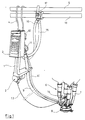
- figure 1 shows a milking equipment with a removal device according to the invention
- figure 2 shows a side view of an operating unit of the removal device according to figure 1
- figure 3 shows a view from above of the operating unit according to figure 1
- figure 4 shows a view of a longitudinal section through the operating unit according to figure 2
- figure 5 shows a view of a section along the line V-V in figure 4.
- the milking equipment shown in figure 1 comprises a frame 1, on which an operating unit 2 and a control means 3 are attached.
- the frame 1 is by means of a clamp 4 suspendable from existing pipe conduits, for instance a vacuum conduit 5.
- a milking means 6 comprising four teat cups 7 and a teat cup claw 8
- a milk hose 9 and a pulsation hose 10 extend to a milk flow meter 11 and a pulsator 12, respectively, carried by the frame 1.
- a cord 13 extends from the operating unit 2 to the teat cup claw 8 and is connected to the latter by means of a connection member 14.
- connection member 17 is adapted to connect the milk hose 15 and the air hose 16 to the milk conduit 18 and the vacuum conduit 5, respectively.
- the operating unit 2 comprises a pneumatically operated, rotating sliding vane motor 19, a cord drum 20, and a planetary gearing 21, which is connected between the motor 19 and the cord drum 20.
- the motor 19 has a rotor shaft 22 with a circular cylindrical mantle 23.
- the mantle 23 there are four radial pockets 24 arranged in two pairs of opposite pockets extending transversely to one another.
- Four vanes 25-28 are slidable in the pockets 24.
- Each pair of opposite vanes 25,27 and 26,28 abut against one another via spacing members in the form of two cylindrical pins 29,30 and 31,32.
- each pair of vanes 25,27 and 26,28 together with their respective associated pins 29,30 and 31,32 forms a unit which is radially slidable relative to the rotor shaft 22.
- the motor 19 has a housing 33, which forms a cylindrical rotor chamber 34 in which the rotor shaft 22 extends in parallel with the centre axis of the rotor chamber 34.
- the extension of the cylindrical rotor chamber 34 transverse to the rotor shaft 22 is substantially constant along the circumference of the rotor chamber 34, which gives the rotor chamber 34 a slightly elliptical cross-section.
- the rotor chamber 34 is divided by the vanes 25-28 into four separate chambers 35-38 disposed in series around the rotor shaft 22.
- the vanes 25-28 seal against the cylindrical wall of the rotor chamber 34 by means of resilient sealing strips 39 arranged on the radially outer ends of the vanes 25-28.
- Each pocket 24 is axially defined by two opposite walls 40,41 with radially outer ends, which constitute parts of two circular surface portions 42,43 of the mantle 23.
- the housing 33 is formed with two inner circular shoulders 44,45, which are situated concentrically with the rotor shaft 22 and axially in front of the respective circular surface portions 42,43 of the mantle 23.
- the shoulders 44,45 of the housing 33 extend close to the surface portions 42,43 of the mantle 23 to seal between the separate chambers 35-38.
- the housing 33 has an inlet member 46 for atmosphere.
- the inlet member 46 is connected to the rotor chamber 34 via an inlet passage 47.
- the housing 33 has an outlet member 48 for connection to a source of vacuum.
- the outlet member 48 is connected to the rotor chamber 34 via an outlet passage 49.
- One end of the rotor shaft 22 is formed with a gear ring 50, which constitutes a sun wheel in the planetary gearing 21.
- the planetary gearing 21 has a stationary gear ring 51 formed in the housing 33.
- Three planet wheels 52 are journalled on the cord drum 20 at the same radial distance from the rotational axis of the cord drum 20 and are in engagement with the gear rings 50 and 51.
- the gear ratio of the planetary gearing 21 is 1:5, which consequently means that the cord drum 20 is rotated one revolution for every five revolutions the rotor shaft 22 is rotated by the motor 19.
- the cord drum 20 is provided with a mounting hole 53, through which one end of the cord 13 can be inserted to enable the cord 13 to be winded on the cord drum 20.
- the housing 33 is provided with an opening 54, through which the cord 13 passes during unwinding and upwinding the cord 13.
- the new removal device is operated in the following way:
- the milker suspends the milking equipment from the vacuum conduit 5 by means of a clamp 4 close to the cow to be milked. Then the milker disengages the milking means 6 from the frame 1 and brings it to the teats of the cow, the cord 13 being unwound from the cord drum 20. Since the motor 19 at this stage is not activated it only exerts a minor braking resistance on the cord drum 20 during the unwinding of the cord 13.
- the milker has applied the teat cups 7 on the teats of the cow the milking starts, extracted milk being passed through the teat cup claw 8, the milk hose 9, the milk flow meter 11, the milk hose 15 and into the milk conduit 18 via the connection member 17.
- the milk flow meter 11 senses the ceasing milk flow and gives a signal to the control means 3, which activates the motor 19 by connecting the outlet member 48 to the vacuum conduit 5 via the air hose 16.
- the control means 3 which activates the motor 19 by connecting the outlet member 48 to the vacuum conduit 5 via the air hose 16.
- an underpressure arises in the outlet passage 49 and in the separate chambers 35-38 which at the time communicate with the outlet passage 49.
- an underpressure arises in the chambers 35 and 38, which results in that the rotor shaft 22 is rotated in counter-clockwise direction.
- the cord drum 20 is turned by the rotor shaft 22 via the planetary gearing 21, so that the cord 13 is wound on the cord drum 20 and pulls the teat cup means 6 off the teats of the cow.
- the motor 19 is nevertheless kept activated until the milker has suspended the milking means 6 from the frame 1.
- the cord 13 may be provided with a retaining member, which retains the cord 13 from unwinding, as the motor is inactivated. In this case the milker releases such a retaining member in connection with the next milking occasion). Then the milker can release the clamp 4 and the hoses 15 and 16 from the vacuum conduit 5 and the connection member 17 and carry the milking equipment to the next cow to be milked.
Landscapes
- Life Sciences & Earth Sciences (AREA)
- Animal Husbandry (AREA)
- Environmental Sciences (AREA)
- External Artificial Organs (AREA)
- Automatic Analysis And Handling Materials Therefor (AREA)
- Control Of Vending Devices And Auxiliary Devices For Vending Devices (AREA)
- Supplying Of Containers To The Packaging Station (AREA)
- Telephone Function (AREA)
Applications Claiming Priority (3)
| Application Number | Priority Date | Filing Date | Title |
|---|---|---|---|
| SE9101997A SE468738B (sv) | 1991-06-28 | 1991-06-28 | Anordning foer automatisk avtagning av mjoelkningsorgan |
| SE9101997 | 1991-06-28 | ||
| PCT/SE1992/000457 WO1993000002A1 (en) | 1991-06-28 | 1992-06-23 | A device for automatic removal of milking means |
Publications (2)
| Publication Number | Publication Date |
|---|---|
| EP0603193A1 EP0603193A1 (en) | 1994-06-29 |
| EP0603193B1 true EP0603193B1 (en) | 1997-08-13 |
Family
ID=20383179
Family Applications (1)
| Application Number | Title | Priority Date | Filing Date |
|---|---|---|---|
| EP92914295A Expired - Lifetime EP0603193B1 (en) | 1991-06-28 | 1992-06-23 | A device for automatic removal of milking means |
Country Status (16)
| Country | Link |
|---|---|
| US (1) | US5431128A (da) |
| EP (1) | EP0603193B1 (da) |
| JP (1) | JP3167134B2 (da) |
| AT (1) | ATE156657T1 (da) |
| CA (1) | CA2112406C (da) |
| CZ (1) | CZ281315B6 (da) |
| DE (1) | DE69221625T2 (da) |
| DK (1) | DK0603193T3 (da) |
| FI (1) | FI100685B (da) |
| HU (1) | HU216404B (da) |
| NO (2) | NO934821D0 (da) |
| NZ (1) | NZ243316A (da) |
| PL (1) | PL167670B1 (da) |
| RU (1) | RU2095973C1 (da) |
| SE (1) | SE468738B (da) |
| WO (1) | WO1993000002A1 (da) |
Families Citing this family (21)
| Publication number | Priority date | Publication date | Assignee | Title |
|---|---|---|---|---|
| US5697324A (en) * | 1993-06-25 | 1997-12-16 | Van Der Lely; Cornelis | Apparatus for automatically milking animals, such as cows |
| SE9302774L (sv) * | 1993-08-27 | 1995-02-28 | Tetra Laval Holdings & Finance | Mjölkningsorganavtagare |
| SE509504C2 (sv) * | 1993-09-16 | 1999-02-01 | Alfa Laval Agri Ab | Automatisk mjölkningsorgansavtagare |
| SE503273C2 (sv) * | 1993-09-16 | 1996-04-29 | Tetra Laval Holdings & Finance | Avtagningsanordning för mjölkningsorgan samt lamellmotor för drivning därav |
| SE501779C2 (sv) * | 1993-09-16 | 1995-05-15 | Tetra Laval Holdings & Finance | Automatisk mjölkningsorgansavtagare |
| SE501780C2 (sv) * | 1993-09-16 | 1995-05-15 | Tetra Laval Holdings & Finance | Lamellmotor med övervarvsskydd |
| NL1001448C1 (nl) * | 1995-06-21 | 1996-12-24 | Maasland Nv | Melkmonsterapparaat. |
| US5809931A (en) * | 1996-02-20 | 1998-09-22 | Alfa Laval Agri Ab | Method and apparatus for positioning milking cluster |
| SE9700119D0 (sv) * | 1997-01-17 | 1997-01-17 | Alfa Laval Agri Ab | Anordning för ett mjölkningsstall |
| SE509449C2 (sv) * | 1997-05-09 | 1999-01-25 | Alfa Laval Agri Ab | Mjölkningsutrustning och avlastningsanordning för mjölkningsutrustning |
| RU2127972C1 (ru) * | 1998-04-14 | 1999-03-27 | Научно-Исследовательский Институт Сельского Хозяйства Центральных Районов Нечерноземной Зоны | Манипулятор доения |
| SE517364C2 (sv) * | 2000-10-03 | 2002-05-28 | Delaval Holding Ab | Upphängningsanordning för fastsättning av ett objekt vid en stödstruktur i ett mjölkningsbås |
| RU2203535C2 (ru) * | 2001-04-16 | 2003-05-10 | Рязанская государственная сельскохозяйственная академия им. проф. П.А. Костычева | Устройство для автоматического снятия доильного аппарата |
| NL1021014C2 (nl) * | 2002-07-05 | 2004-01-06 | Lely Entpr Ag | Inrichting voor het melken van een dier. |
| US6814027B2 (en) * | 2002-09-12 | 2004-11-09 | Westfaliasurge, Inc. | Milker unit detacher for rotary milking parlor |
| RU2257707C1 (ru) * | 2004-02-09 | 2005-08-10 | Государственное научное учреждение "Всероссийский научно-исследовательский и проектно-технологический институт механизации и электрификации сельского хозяйства" (ВНИПТИМЭСХ) | Двухрежимный доильный аппарат |
| DE102004042088A1 (de) * | 2004-08-31 | 2006-03-02 | Westfaliasurge Gmbh | Vorrichtung zum Abziehen von Melkbechern |
| WO2009048412A1 (en) * | 2007-10-09 | 2009-04-16 | Delaval Holding Ab | A milking member and method of preparing it for attachment |
| US9215858B2 (en) * | 2010-09-07 | 2015-12-22 | Delaval Holding Ab | Cabinet in a milking parlour |
| RU2534511C1 (ru) * | 2013-04-02 | 2014-11-27 | Федеральное государственное бюджетное образовательное учреждение высшего профессионального образования "Рязанский государственный агротехнологический университет имени П.А. Костычева" | Устройство для автоматического снятия доильного аппарата |
| DE102014107124A1 (de) * | 2014-05-20 | 2015-11-26 | Gea Farm Technologies Gmbh | Armeinrichtung für eine Melkstandanordnung zum automatischen Melken von milchgebenden Tieren, Platzteiler einer Melkstandanordnung und Melkstandanordnung |
Family Cites Families (18)
| Publication number | Priority date | Publication date | Assignee | Title |
|---|---|---|---|---|
| GB417348A (en) * | 1933-07-05 | 1934-10-03 | Nichols Compressors Ltd | Improvements in rotary type exhausters, compressors, superchargers and the like |
| GB463417A (en) * | 1935-09-26 | 1937-03-30 | Archibald Frazer Nash | Improvements in and relating to hydraulic motors, rotary engines, pumps, blowers and the like |
| US3150842A (en) * | 1962-03-20 | 1964-09-29 | Robert M Weber | Vehicle mounted wire winder |
| US3471885A (en) * | 1966-06-15 | 1969-10-14 | John Mcloughlin | Hydro driven hose washer and winder |
| US3435732A (en) * | 1966-07-15 | 1969-04-01 | Gilreath Hydraulics Inc | Hydraulically powered drilling sub |
| SE361400B (da) * | 1972-05-03 | 1973-11-05 | Alfa Laval Ab | |
| US3789798A (en) * | 1972-08-10 | 1974-02-05 | Sta Rite Industries | Automatic milking unit |
| DE2400141A1 (de) * | 1974-01-03 | 1975-07-10 | Artur Foehl | Sicherheitsgurt-einziehvorrichtung |
| US3893422A (en) * | 1974-05-10 | 1975-07-08 | Dec Int | Milking unit support and detacher mechanism |
| US4034713A (en) * | 1975-11-04 | 1977-07-12 | Umbaugh Raymond E | Milking system and method |
| US4385873A (en) * | 1980-10-07 | 1983-05-31 | Richter Hans H | Rotary vane type pump or motor and the like with circular chamber portions |
| NL8202453A (nl) * | 1982-06-17 | 1984-01-16 | Kummer Electronics Bv | Afname-apparaat voor een melkstel van een melkmachine, in het bijzonder voor een grupstal. |
| US4473196A (en) * | 1982-08-31 | 1984-09-25 | Sammann Ernest F | Hydraulically actuated wire roller for a tractor |
| DD233480A1 (de) * | 1984-12-29 | 1986-03-05 | Fortschritt Veb K | Melkzeugabnahmevorrichtung |
| NL8502434A (nl) * | 1985-09-04 | 1987-04-01 | Multinorm Bv | Melkinrichting. |
| NL8502694A (nl) * | 1985-10-02 | 1987-05-04 | Kummer Electronics Bv | Afnameapparaat voor een melkstel, in het bijzonder voor een grupstal. |
| DE3774217D1 (de) * | 1986-08-27 | 1991-12-05 | Lely Nv C Van Der | Geraet zum melken von tieren. |
| US4838203A (en) * | 1987-07-21 | 1989-06-13 | Alfa-Laval, Inc. | Milking claw retraction and retention device for milking machine |
-
1991
- 1991-06-28 SE SE9101997A patent/SE468738B/sv not_active IP Right Cessation
-
1992
- 1992-06-23 WO PCT/SE1992/000457 patent/WO1993000002A1/en not_active Ceased
- 1992-06-23 HU HU9303725A patent/HU216404B/hu not_active IP Right Cessation
- 1992-06-23 EP EP92914295A patent/EP0603193B1/en not_active Expired - Lifetime
- 1992-06-23 DK DK92914295.8T patent/DK0603193T3/da active
- 1992-06-23 DE DE69221625T patent/DE69221625T2/de not_active Expired - Lifetime
- 1992-06-23 AT AT92914295T patent/ATE156657T1/de not_active IP Right Cessation
- 1992-06-23 JP JP50124193A patent/JP3167134B2/ja not_active Expired - Lifetime
- 1992-06-23 CZ CS932864A patent/CZ281315B6/cs not_active IP Right Cessation
- 1992-06-23 PL PL92301955A patent/PL167670B1/pl unknown
- 1992-06-23 RU RU9293058551A patent/RU2095973C1/ru active
- 1992-06-23 US US08/167,944 patent/US5431128A/en not_active Expired - Lifetime
- 1992-06-23 CA CA002112406A patent/CA2112406C/en not_active Expired - Lifetime
- 1992-06-25 NZ NZ243316A patent/NZ243316A/en not_active IP Right Cessation
-
1993
- 1993-12-27 NO NO934821D patent/NO934821D0/no unknown
- 1993-12-27 NO NO934821A patent/NO178952C/no not_active IP Right Cessation
- 1993-12-27 FI FI935875A patent/FI100685B/fi active
Also Published As
| Publication number | Publication date |
|---|---|
| EP0603193A1 (en) | 1994-06-29 |
| NO178952B (no) | 1996-04-01 |
| CA2112406C (en) | 2002-09-17 |
| CZ286493A3 (en) | 1995-03-15 |
| SE9101997D0 (sv) | 1991-06-28 |
| CZ281315B6 (cs) | 1996-08-14 |
| DK0603193T3 (da) | 1997-10-27 |
| DE69221625D1 (de) | 1997-09-18 |
| HU9303725D0 (en) | 1994-04-28 |
| NO178952C (no) | 1996-07-10 |
| JP3167134B2 (ja) | 2001-05-21 |
| HUT69849A (en) | 1995-09-28 |
| RU2095973C1 (ru) | 1997-11-20 |
| FI100685B (fi) | 1998-02-13 |
| CA2112406A1 (en) | 1993-01-07 |
| NZ243316A (en) | 1993-12-23 |
| FI935875A0 (fi) | 1993-12-27 |
| PL167670B1 (pl) | 1995-10-31 |
| ATE156657T1 (de) | 1997-08-15 |
| NO934821D0 (no) | 1993-12-27 |
| SE468738B (sv) | 1993-03-15 |
| HU216404B (hu) | 1999-06-28 |
| SE9101997L (sv) | 1992-12-29 |
| NO934821L (no) | 1993-12-27 |
| JPH06508521A (ja) | 1994-09-29 |
| US5431128A (en) | 1995-07-11 |
| DE69221625T2 (de) | 1997-12-18 |
| WO1993000002A1 (en) | 1993-01-07 |
| FI935875L (fi) | 1993-12-27 |
Similar Documents
| Publication | Publication Date | Title |
|---|---|---|
| EP0603193B1 (en) | A device for automatic removal of milking means | |
| US4596381A (en) | Apparatus and method for installing line in conduit | |
| US4202531A (en) | Pneumatic rodding of conduit using everted flexible tubing | |
| US5350514A (en) | Centrifuge | |
| RU93058551A (ru) | Устройство для автоматического снятия доильного аппарата | |
| US4315522A (en) | Fluid distribution apparatus | |
| US6802336B1 (en) | Hose reel apparatus | |
| US3039715A (en) | Rod reel device | |
| WO1995008048A1 (en) | Removal device for a milking means and a sliding vane motor for the operation thereof | |
| CN101511165A (zh) | 挤奶设备 | |
| US7984693B2 (en) | Device and method for removing teat cups | |
| JP3127420B2 (ja) | エアーホースリール | |
| RU2203535C2 (ru) | Устройство для автоматического снятия доильного аппарата | |
| JP2559269B2 (ja) | 線条の巻取ボビン | |
| US3100475A (en) | Adapters for milking systems | |
| KR19990084090A (ko) | 폐비닐 수거장치 | |
| SE509504C2 (sv) | Automatisk mjölkningsorgansavtagare | |
| JP3047549U (ja) | 管路内への通線装置 | |
| US2858085A (en) | Controlled power driven reel | |
| RU2036580C1 (ru) | Манипулятор доения | |
| JP4054924B2 (ja) | ベルト成型用金型への芯線巻回装置及びこれに使用されるベルト成型用金型 | |
| CA2171609C (en) | Automatic milking means removal device | |
| KR100378230B1 (ko) | 노후상하수관용 폴리에틸렌 라이너의 절첩 묶음 장치 | |
| KR810001867B1 (ko) | 타이어 성형기 | |
| JP2000264546A (ja) | ホースリール |
Legal Events
| Date | Code | Title | Description |
|---|---|---|---|
| PUAI | Public reference made under article 153(3) epc to a published international application that has entered the european phase |
Free format text: ORIGINAL CODE: 0009012 |
|
| 17P | Request for examination filed |
Effective date: 19931122 |
|
| AK | Designated contracting states |
Kind code of ref document: A1 Designated state(s): AT BE CH DE DK ES FR GB IT LI NL SE |
|
| 17Q | First examination report despatched |
Effective date: 19950817 |
|
| GRAG | Despatch of communication of intention to grant |
Free format text: ORIGINAL CODE: EPIDOS AGRA |
|
| GRAH | Despatch of communication of intention to grant a patent |
Free format text: ORIGINAL CODE: EPIDOS IGRA |
|
| GRAH | Despatch of communication of intention to grant a patent |
Free format text: ORIGINAL CODE: EPIDOS IGRA |
|
| GRAA | (expected) grant |
Free format text: ORIGINAL CODE: 0009210 |
|
| AK | Designated contracting states |
Kind code of ref document: B1 Designated state(s): AT BE CH DE DK ES FR GB IT LI NL SE |
|
| PG25 | Lapsed in a contracting state [announced via postgrant information from national office to epo] |
Ref country code: LI Free format text: LAPSE BECAUSE OF FAILURE TO SUBMIT A TRANSLATION OF THE DESCRIPTION OR TO PAY THE FEE WITHIN THE PRESCRIBED TIME-LIMIT Effective date: 19970813 Ref country code: IT Free format text: LAPSE BECAUSE OF FAILURE TO SUBMIT A TRANSLATION OF THE DESCRIPTION OR TO PAY THE FEE WITHIN THE PRESCRIBED TIME-LIMIT;WARNING: LAPSES OF ITALIAN PATENTS WITH EFFECTIVE DATE BEFORE 2007 MAY HAVE OCCURRED AT ANY TIME BEFORE 2007. THE CORRECT EFFECTIVE DATE MAY BE DIFFERENT FROM THE ONE RECORDED. Effective date: 19970813 Ref country code: ES Free format text: THE PATENT HAS BEEN ANNULLED BY A DECISION OF A NATIONAL AUTHORITY Effective date: 19970813 Ref country code: CH Free format text: LAPSE BECAUSE OF FAILURE TO SUBMIT A TRANSLATION OF THE DESCRIPTION OR TO PAY THE FEE WITHIN THE PRESCRIBED TIME-LIMIT Effective date: 19970813 Ref country code: BE Effective date: 19970813 Ref country code: AT Effective date: 19970813 |
|
| REF | Corresponds to: |
Ref document number: 156657 Country of ref document: AT Date of ref document: 19970815 Kind code of ref document: T |
|
| REG | Reference to a national code |
Ref country code: CH Ref legal event code: EP |
|
| REF | Corresponds to: |
Ref document number: 69221625 Country of ref document: DE Date of ref document: 19970918 |
|
| REG | Reference to a national code |
Ref country code: DK Ref legal event code: T3 |
|
| PG25 | Lapsed in a contracting state [announced via postgrant information from national office to epo] |
Ref country code: SE Effective date: 19971113 |
|
| ET | Fr: translation filed | ||
| REG | Reference to a national code |
Ref country code: CH Ref legal event code: PL |
|
| PLBE | No opposition filed within time limit |
Free format text: ORIGINAL CODE: 0009261 |
|
| STAA | Information on the status of an ep patent application or granted ep patent |
Free format text: STATUS: NO OPPOSITION FILED WITHIN TIME LIMIT |
|
| 26N | No opposition filed | ||
| REG | Reference to a national code |
Ref country code: GB Ref legal event code: IF02 |
|
| PGFP | Annual fee paid to national office [announced via postgrant information from national office to epo] |
Ref country code: DK Payment date: 20080626 Year of fee payment: 17 Ref country code: NL Payment date: 20080624 Year of fee payment: 17 |
|
| PGFP | Annual fee paid to national office [announced via postgrant information from national office to epo] |
Ref country code: FR Payment date: 20080617 Year of fee payment: 17 |
|
| PGFP | Annual fee paid to national office [announced via postgrant information from national office to epo] |
Ref country code: GB Payment date: 20090625 Year of fee payment: 18 |
|
| REG | Reference to a national code |
Ref country code: DK Ref legal event code: EBP |
|
| NLV4 | Nl: lapsed or anulled due to non-payment of the annual fee |
Effective date: 20100101 |
|
| REG | Reference to a national code |
Ref country code: FR Ref legal event code: ST Effective date: 20100226 |
|
| PG25 | Lapsed in a contracting state [announced via postgrant information from national office to epo] |
Ref country code: FR Free format text: LAPSE BECAUSE OF NON-PAYMENT OF DUE FEES Effective date: 20090630 |
|
| PG25 | Lapsed in a contracting state [announced via postgrant information from national office to epo] |
Ref country code: NL Free format text: LAPSE BECAUSE OF NON-PAYMENT OF DUE FEES Effective date: 20100101 Ref country code: DK Free format text: LAPSE BECAUSE OF NON-PAYMENT OF DUE FEES Effective date: 20090630 |
|
| GBPC | Gb: european patent ceased through non-payment of renewal fee |
Effective date: 20100623 |
|
| PG25 | Lapsed in a contracting state [announced via postgrant information from national office to epo] |
Ref country code: GB Free format text: LAPSE BECAUSE OF NON-PAYMENT OF DUE FEES Effective date: 20100623 |
|
| PGFP | Annual fee paid to national office [announced via postgrant information from national office to epo] |
Ref country code: DE Payment date: 20110622 Year of fee payment: 20 |
|
| REG | Reference to a national code |
Ref country code: DE Ref legal event code: R071 Ref document number: 69221625 Country of ref document: DE |
|
| REG | Reference to a national code |
Ref country code: DE Ref legal event code: R071 Ref document number: 69221625 Country of ref document: DE |
|
| PG25 | Lapsed in a contracting state [announced via postgrant information from national office to epo] |
Ref country code: DE Free format text: LAPSE BECAUSE OF EXPIRATION OF PROTECTION Effective date: 20120626 |