EP0603203B1 - Zahnärztliches handstück - Google Patents
Zahnärztliches handstück Download PDFInfo
- Publication number
- EP0603203B1 EP0603203B1 EP92916540A EP92916540A EP0603203B1 EP 0603203 B1 EP0603203 B1 EP 0603203B1 EP 92916540 A EP92916540 A EP 92916540A EP 92916540 A EP92916540 A EP 92916540A EP 0603203 B1 EP0603203 B1 EP 0603203B1
- Authority
- EP
- European Patent Office
- Prior art keywords
- neck
- handle part
- handpiece
- coolant
- coolant conduit
- Prior art date
- Legal status (The legal status is an assumption and is not a legal conclusion. Google has not performed a legal analysis and makes no representation as to the accuracy of the status listed.)
- Expired - Lifetime
Links
Images




Classifications
-
- A—HUMAN NECESSITIES
- A61—MEDICAL OR VETERINARY SCIENCE; HYGIENE
- A61C—DENTISTRY; APPARATUS OR METHODS FOR ORAL OR DENTAL HYGIENE
- A61C1/00—Dental machines for boring or cutting ; General features of dental machines or apparatus, e.g. hand-piece design
- A61C1/02—Dental machines for boring or cutting ; General features of dental machines or apparatus, e.g. hand-piece design characterised by the drive of the dental tools
- A61C1/05—Dental machines for boring or cutting ; General features of dental machines or apparatus, e.g. hand-piece design characterised by the drive of the dental tools with turbine drive
- A61C1/052—Ducts for supplying driving or cooling fluid, e.g. air, water
-
- A—HUMAN NECESSITIES
- A61—MEDICAL OR VETERINARY SCIENCE; HYGIENE
- A61C—DENTISTRY; APPARATUS OR METHODS FOR ORAL OR DENTAL HYGIENE
- A61C1/00—Dental machines for boring or cutting ; General features of dental machines or apparatus, e.g. hand-piece design
- A61C1/08—Machine parts specially adapted for dentistry
- A61C1/18—Flexible shafts; Clutches or the like; Bearings or lubricating arrangements; Drives or transmissions
Definitions
- the invention relates to a dental handpiece consisting of a handle part, with which various neck parts can optionally be connected, which carry head parts for holding tools, at least one coolant line being guided through the handle part.
- the object of the invention is to provide a dental handpiece, the handle part of which can be used as universally as possible.
- the neck part is provided with at least one attachment for closing or opening a coolant line passing through the handle part.
- the attachment provided on the neck part according to the invention closes a coolant line which normally runs open in the handle part. It is just as well possible to normally close this line by means of a valve, which is optionally opened by the attachment provided on the neck part.
- a dental handpiece is known in which, in contrast to the invention, the coolant lines are not closable in the neck part of the handpiece, but are arranged in the connecting part between the micromotor and supply hose or between the micromotor and handpiece.
- the proposal according to the invention makes it possible, above all, not only to have a coolant line led through the handle part end at a fixed point, but also to provide two or more exit points for this line, the coolant flow being passed on to the neck part depending on the type of neck part used or Not.
- a dental handpiece in which the grip part has an arm that grips under the neck part, which extends over the entire length of the neck part and has outlet openings for cooling water and cooling air at its end. Even with such an arrangement, the invention can be used to guide the cooling media either through the neck part or through the arms under it.
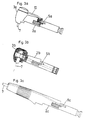
- FIGS. 1a and b show from the side and from above each in section the handle part of a dental handpiece
- 2a-c show a top view of the neck parts that can be connected to the handle part according to FIG. 1, each made in one piece with a head part
- FIGS. 3a-c show the corresponding side views
- FIGS. 4a-c show the connection point of the handle part and neck part corresponding to 2a-c 5a-c show a constructive variant of FIGS. 4a-c
- FIG. 5d the associated handle part in the starting position.
- the handle part 1 in Fig. 1a and 1b each comprises a drive shaft 11, which drives directly or via a gear 12 end edges 13 and 14, via which the rotary movement to a shaft in a neck part 2b and head part 3 existing tool carriers is conveyed.
- a coolant line 4 which branches into two arms, of which the arm 4 'ends in the parting plane of the handle part 1 and neck part 2, whereas the arm 4''is guided to the front end of the handle part 1, where from a spray is formed between the cooling water and the cooling air that is also supplied.
- both the branch 4 'and the branch 4' 'of the coolant line contribute to the coolant supply to the instrument.
- the branches 4 ' continue in the manner shown in FIGS. 4a and 5a in the handpiece 2a and serve to effect internal cooling of the tool 7 via a line 10.
- the branches 4 ′′ are guided in the manner shown in FIG. 1 to form a cooling spray at the tip of the handle part 1.
- the invention allows the coolant supply of the handle part 1 to be used only partially by closing off the branch 4 'of the coolant line by means of an extension 5b, so that only the tip of the handle part 1 is supplied with water for spray formation .
- FIGS. 4a-c The simplest constructive implementation of the inventive concept is shown in FIGS. 4a-c.
- O-rings 8 are provided for sealing at the point at which the coolant line 4 divides into the two branches 4 'and 4' '.
- the approaches 5 a - c are either rod-shaped or tubular. If it is desired to keep the coolant line 4 basically closed, the construction shown in FIG. 5d can achieve the same effect as that shown in FIG. 4. Only one valve 6 is provided, which coolant line 4 is in the idle state holds closed and which is opened by suitable approaches 5'a - 5'c of the handpieces 2a - 2c.
- FIG. 4a-c In the case of the exemplary embodiment according to FIG.
- the coolant is passed on through the attachment 5'a on the one hand, and on the other hand via the bores 9 in the attachment 5'a via the branch 4 '' of the coolant line.
- attachment 5'b closes branch 4 'and opens the inflow to branch 4' '.
- the branch 4 ′′ is closed and the branch 4 ′ is supplied with coolant.
Landscapes
- Health & Medical Sciences (AREA)
- Oral & Maxillofacial Surgery (AREA)
- Dentistry (AREA)
- Epidemiology (AREA)
- Life Sciences & Earth Sciences (AREA)
- Animal Behavior & Ethology (AREA)
- General Health & Medical Sciences (AREA)
- Public Health (AREA)
- Veterinary Medicine (AREA)
- Dental Tools And Instruments Or Auxiliary Dental Instruments (AREA)
Abstract
Description
- Die Erfindung bezieht sich auf ein zahnärztliches Handstück bestehend aus einem Griffteil, mit dem wahlweise verschiedene Halsteile verbindbar sind, welche Kopfteile zur Aufnahme von Werkzeugen tragen, wobei durch den Griffteil mindestens eine Kühlmittelleitung geführt ist.
- Es ist bekannt, derartige Handstücke so auszubilden, daß ein Griffteil mit verschiedenen Halsteilen verbunden werden kann. Dabei ist jedoch immer vorgesehen, daß die durch den Griffteil geführten Kühlmittelleitungen, die in der Trennfläche von Griffteil und Halsteil enden, im Halsteil fortgesetzt werden (vgl. AT-A-359 632, AT-A-370 979).
- Aufgabe der Erfindung ist es demgegenüber ein zahnärztliches Handstück zu schaffen, dessen Griffteil möglichst universell verwendbar ist. In diesem Sinne ist erfindungsgemäß vorgesehen, daß der Halsteil mit mindestens einem Ansatz zum Verschließen oder Öffnen einer den Griffteil durchsetzenden Kühlmittelleitung versehen ist.
- In einer Ausführungsform der Erfindung ist vorgesehen, daß der erfindungsgemäß am Halsteil vorgesehene Ansatz eine im Normalfall offen im Griffteil verlaufende Kühlmittelleitung verschließt. Genauso gut ist es möglich, diese Leitung im Normalfall durch ein Ventil abzuschließen, welches wahlweise durch den am Halsteil vorgesehenen Ansatz geöffnet wird.
- Aus der FR-A 2 325 353 ist ein zahnärztliches Handstück bekannt, in dem die Kühlmittelleitungen im Gegensatz zur Erfindung nicht verschließbar im Halsteil des Handstückes, sondern im Verbindungsteil zwischen Micromotor und Zuführungsschlauch oder zwischen Micromotor und Handstück angeordnet sind.
- Durch die erfindungsgemäße Maßnahme ist es nicht mehr notwendig, den Griffteil des zahnärztlichen Handstückes auszuwechseln, wenn ein Übergang zwischen Halsteilen mit verschiedenem Kühlmittelbedarf erfolgt.
- Der erfindungsgemäße Vorschlag erlaubt es vor allem, eine durch den Griffteil geführte Kühlmittelleitung nicht nur an einer fixen Stelle enden zu lassen, sondern für diese Leitung zwei oder mehrere Austrittsstellen vorzusehen, wobei je nach der Art des verwendeten Halsteiles der Kühlmittelstrom in den Halsteil weitergeleitet wird oder nicht.
- Aus dem DE-U 85 10 667 ist ein zahnärztliches Handstück bekannt, bei dem der Griffteil einen den Halsteil untergreifenden Arm aufweist, welcher sich über die ganze Länge des Halsteiles erstreckt und an seinem Ende Austrittsöffnungen für Kühlwasser und Kühlluft aufweist. Auch bei einer derartigen Anordnung kann die Erfindung eingesetzt werden, um die Kühlmedien wahlweise durch den Halsteil oder den diese untergreifenden Arme zu leiten.
- Einzelheiten der Erfindung werden anschließend anhand der Zeichnung erläutert.
- Fig. 1a und b zeigen von der Seite und von oben jeweils im Schnitt den Griffteil eines zahnärztlichen Handstückes,
Fig. 2a - c zeigen mit dem Griffteil nach Fig. 1 verbindbare, jeweils einstückig mit einem Kopfteil ausgeführte Halsteile in Draufsicht, Fig. 3a - c die entsprechenden Seitenansichten, Fig. 4a - c zeigen die Verbindungsstelle von Griffteil und Halsteil entsprechend 2a - c, Fig. 5a - c zeigen eine konstruktive Variante zu Fig. 4a - c, Fig. 5d den zugehörigen Griffteil in der Ausgangsstellung. - Der Griffteil 1 in Fig. 1a und 1b umfaßt jeweils eine Antriebswelle 11, welche direkt bzw. über ein Getriebe 12 Stirnränder 13 und 14 antreibt, über welche die Drehbewegung an eine Welle in einem aus Halsteil 2b und Kopfteil 3 bestehenden Werkzeugträger vermittelt wird. Durch den Griffteil 1 verläuft eine Kühlmittelleitung 4, welche sich in Zwei Arme verzweigt, von denen der Arm 4' in die Trennebene vom Griffteil 1 und Halsteil 2 endet, wogegen der Arm 4'' bis zum Vorderende des Griffteiles 1 geführt ist, wo aus dem Kühlwasser und ebenfalls zugeführter Kühlluft ein Spray gebildet wird.
- Wesentlich für den dargestellten Griffteil 1 ist die Möglichkeit, Werkzeugträger daran anzuschließen, welche in verschiedener Weise mit einem Kühlmedium, insbesondere mit Kühlwasser versorgt werden sollen.
- Im Falle des Ausführungsbeispieles nach Fig. 2a bzw. Fig. 3a liegt insofern noch eine konventionelle Lösung vor, als sowohl der Ast 4' als auch der Ast 4'' der Kühlmittelleitung zur Kühlmittelversorgung des Instrumentes beitragen. Die Äste 4' setzen sich in der aus Fig. 4a und 5a im Detail ersichtlichen Weise in das Handstück 2a fort und dienen dazu, über eine Leitung 10 eine Innenkühlung des Werkzeuges 7 zu bewirken. Die Äste 4'' werden in der aus Fig. 1 ersichtlichen Weise zur Bildung eines Kühlsprays an die Spitze des Griffteiles 1 geführt.
- Wie aus Fig. 2b und 3b ersichtlich, erlaubt es jedoch die Erfindung, das Kühlmittelangebot des Griffteiles 1 nur teilweise auszunützen, indem durch einen Ansatz 5b der Ast 4' der Kühlmittelleitung verschlossen wird, sodaß lediglich der Spitze des Griffteiles 1 Wasser zur Spraybildung zugeführt wird.
- Umgekehrt wie in Fig. 2c und 3c dargestellt, ist es andererseits möglich, das Kühlmittel durch einen gemäß Fig. 4c ausgebildeten Ansatz 5c lediglich in den hier gerade ausgebildeten Halsteil 2c weiterzuleiten, ohne von der Möglichkeit der Spraybildung am Ende des Griffteiles 1 Gebrauch zu machen.
- Die einfachste konstruktive Durchführung des Erfindungsgedankens zeigen an sich Fig. 4a - c. Hier sind lediglich an jener Stelle, an der sich die Kühlmittelleitung 4 in die beiden Äste 4' und 4'' teilt, O-Ringe 8 zur Dichtung vorgesehen. Die Ansätze 5 a - c sind entweder stab- oder rohrförmig ausgebildet. Wenn es gewünscht ist, die Kühlmittelleitung 4 grundsätzlich verschlossen zu halten, kann mit der in Fig. 5d dargestellten Konstruktion die gleiche Wirkung erzielt werden, wie mit jener gemäß Fig. 4. Es ist lediglich ein Ventil 6 vorzusehen, welches im Ruhezustand die Kühlmittelleitung 4 verschlossen hält und welches durch geeignete Ansätze 5'a - 5'c der Handstücke 2a - 2c geöffnet wird. Dabei erfolgt im Falle des Ausführungsbeispieles nach Fig. 5a eine Weiterleitung des Kühlmittels einerseits durch den Ansatz 5'a, andererseits über die Bohrungen 9 im Ansatz 5'a über den Ast 4'' der Kühlmittelleitung. Im Fall des Ausführungsbeispieles 5b verschließt der Ansatz 5'b den Ast 4' und öffnet den Zufluß zum Ast 4''. Beim Ausführungsbeispiel gemäß Fig. 5c wird der Ast 4'' geschlossen und der Ast 4' mit Kühlmittel versorgt.
Claims (6)
- Zahnärztliches Handstück bestehend aus einem Griffteil, mit dem wahlweise verschiedene Halsteile verbindbar sind, welche Kopfteile zur Aufnahme von Werkzeugen tragen, wobei durch den Griffteil mindestens eine Kühlmittelleitung geführt ist, dadurch gekennzeichnet, daß der Halsteil (2) mit mindestens einem Ansatz (5b, 5c, 5'a, 5'b, 5'c) zum Verschließen oder Öffnen einer den Griffteil (1) durchsetzenden Kühlmittelleitung (4, 4', 4'') versehen ist.
- Handstück nach Anspruch 1, dadurch gekennzeichnet, daß die Kühlmittelleitung (4) sich in zwei Äste (4', 4'') verzweigt, welche durch Halsteile (2) mit verschieden gestalteten Ansätzen (5b, 5c, 5'a,5'b,5'c) wahlweise verschließbar bzw. öffenbar sind.
- Handstück nach Anspruch 2, dadurch gekennzeichnet, daß an jener Stelle, an der sich die Kühlmittelleitung (4,4', 4'') in die beiden Äste (4',4'') teilt, O-ringe (8) zur Dichtung vorgesehen sind.
- Handstück nach Anspruch 1 oder 2, dadurch gekennzeichnet, daß ein die Kühlmittelleitung (4,4',4'') im Ruhezustand verschließendes Ventil (6) vorgesehen ist, welches vom Ansatz (5'a,5'b,5'c) öffenbar ist.
- Handstück nach einem der Ansprüche 1 bis 4, dadurch gekennzeichnet, daß ein Halsteil (2) einen stabförmig (5b) ausgebildeten Ansatz aufweist.
- Handstück nach einem der Ansprüche 1 bis 4, dadurch gekennzeichnet, daß ein Halsteil (2) einen rohrförmig ausgebildeten Ansatz (5a,5c) aufweist.
Applications Claiming Priority (3)
| Application Number | Priority Date | Filing Date | Title |
|---|---|---|---|
| AT1838/91 | 1991-09-13 | ||
| AT0183891A AT396742B (de) | 1991-09-13 | 1991-09-13 | Zahnärztliches handstück |
| PCT/AT1992/000108 WO1993005722A1 (de) | 1991-09-13 | 1992-08-06 | Zahnärztliches handstück |
Publications (2)
| Publication Number | Publication Date |
|---|---|
| EP0603203A1 EP0603203A1 (de) | 1994-06-29 |
| EP0603203B1 true EP0603203B1 (de) | 1995-11-02 |
Family
ID=3522114
Family Applications (1)
| Application Number | Title | Priority Date | Filing Date |
|---|---|---|---|
| EP92916540A Expired - Lifetime EP0603203B1 (de) | 1991-09-13 | 1992-08-06 | Zahnärztliches handstück |
Country Status (6)
| Country | Link |
|---|---|
| US (1) | US5482462A (de) |
| EP (1) | EP0603203B1 (de) |
| JP (1) | JPH06510679A (de) |
| AT (1) | AT396742B (de) |
| DE (1) | DE59204210D1 (de) |
| WO (1) | WO1993005722A1 (de) |
Families Citing this family (7)
| Publication number | Priority date | Publication date | Assignee | Title |
|---|---|---|---|---|
| FR2708193B1 (fr) * | 1993-06-29 | 1996-07-05 | Satelec Sa | Instrument chirurgical, destiné notamment à la chirurgie dentaire. |
| US6012922A (en) * | 1997-09-08 | 2000-01-11 | Tulsa Dental Products Inc. | Axial displacement bearing connecting a multi-section shaft for quick removal of dental tools from a handpiece |
| USD578726S1 (en) | 2004-11-12 | 2008-10-21 | Edwards Philip L | Dog bone |
| US20060102099A1 (en) * | 2004-11-12 | 2006-05-18 | Edwards Philip L | Polymeric dog bone |
| US7629315B2 (en) | 2005-03-09 | 2009-12-08 | University Of Pittsburgh Of The Commonwealth System Of Higher Education | Compositions for blocking the inhibitory effect of human CRP on human leptin |
| US20070190484A1 (en) * | 2006-02-10 | 2007-08-16 | Dentsply International Inc. | Closed loop speed control for a pneumatic dental handpiece |
| US8303304B2 (en) | 2006-12-18 | 2012-11-06 | Dentsply International, Inc. | Closed loop speed control for a pneumatic dental handpiece |
Family Cites Families (15)
| Publication number | Priority date | Publication date | Assignee | Title |
|---|---|---|---|---|
| GB1441617A (en) * | 1973-05-02 | 1976-07-07 | Cmw Lab Ltd | Coupling |
| DE2542826C3 (de) * | 1975-09-25 | 1978-07-27 | Siemens Ag, 1000 Berlin Und 8000 Muenchen | Vorrichtung zur Versorgung eines mit einem Antrieb für ein zahnärztliches Werkzeug versehenen Handstückes mit Kühlmittel |
| DE2549177C3 (de) * | 1975-11-03 | 1985-10-03 | Siemens AG, 1000 Berlin und 8000 München | Kupplungsvorrichtung für zahnärztliche Handstücke |
| DE2558064C3 (de) * | 1975-12-22 | 1987-01-22 | Siemens AG, 1000 Berlin und 8000 München | Zahnärztliche Handstückanordnung |
| DE2741148C2 (de) * | 1977-09-13 | 1986-12-04 | Kaltenbach & Voigt Gmbh & Co, 7950 Biberach | Zahnärztliches Handstück |
| DE2855682A1 (de) * | 1978-12-22 | 1980-07-03 | Siemens Ag | Vorrichtung zum loesbaren verbinden von zwei axial miteinander kuppelbaren zahnaerztlichen handstueck- o.dgl. -teilen |
| AT359632B (de) * | 1979-02-12 | 1980-11-25 | Buermoos Dentalwerk | Zahnaerztliches handstueck |
| US4260382A (en) * | 1980-01-23 | 1981-04-07 | Thomson Loronzo H | Air turbine dental handpieces and swivel connections therefor |
| FR2478994A1 (fr) * | 1980-03-27 | 1981-10-02 | Micro Mega Sa | Dispositif pour l'accouplement rigide d'un tube d'alimentation en fluide de refroidissement a une piece a main de dentisterie |
| DE3243294A1 (de) * | 1982-11-23 | 1984-05-24 | Siemens AG, 1000 Berlin und 8000 München | Steuereinrichtung fuer in einem zahnaerztlichen geraet in ablagen gehalterte instrumente |
| DE8510667U1 (de) * | 1985-04-11 | 1986-08-07 | Hüttenmoser, Hans, Kronbühl | Zahnärztliche Handstückanordnung |
| US5156546A (en) * | 1988-06-13 | 1992-10-20 | Robert Constantine, Inc. | Dental equipment cleaning apparatus and method |
| US4957483A (en) * | 1988-10-21 | 1990-09-18 | Den-Tal-Ez, Inc. | Sterilizable syringe |
| DE3930114A1 (de) * | 1989-05-23 | 1990-11-29 | Alfred Leiter | Arbeitsgeraet fuer medizinische zwecke |
| US5039304A (en) * | 1990-11-05 | 1991-08-13 | Midwest Dental Products Corporation | Quick connect/disconnect coupling for dental handpieces |
-
1991
- 1991-09-13 AT AT0183891A patent/AT396742B/de not_active IP Right Cessation
-
1992
- 1992-08-06 JP JP5505610A patent/JPH06510679A/ja active Pending
- 1992-08-06 DE DE59204210T patent/DE59204210D1/de not_active Expired - Fee Related
- 1992-08-06 WO PCT/AT1992/000108 patent/WO1993005722A1/de not_active Ceased
- 1992-08-06 EP EP92916540A patent/EP0603203B1/de not_active Expired - Lifetime
-
1994
- 1994-03-14 US US08/204,334 patent/US5482462A/en not_active Expired - Fee Related
Also Published As
| Publication number | Publication date |
|---|---|
| WO1993005722A1 (de) | 1993-04-01 |
| DE59204210D1 (de) | 1995-12-07 |
| ATA183891A (de) | 1993-04-15 |
| JPH06510679A (ja) | 1994-12-01 |
| AT396742B (de) | 1993-11-25 |
| US5482462A (en) | 1996-01-09 |
| EP0603203A1 (de) | 1994-06-29 |
Similar Documents
| Publication | Publication Date | Title |
|---|---|---|
| DE2811398C2 (de) | Schere | |
| EP0611632B1 (de) | Beidhändig geführtes Elektrohandwerkzeug mit Griffbügel | |
| DE3346651C2 (de) | ||
| CH695659A5 (de) | Zubehörträger für eine elektrische Zahnbürste. | |
| DE3526684C1 (de) | Spannvorrichtung zum Einspannen von insbesondere Zahnwerkzeugen | |
| DE19817704C2 (de) | Zahnbürste mit schwenkbeweglichen Borstenbüscheln | |
| DE10200245B4 (de) | Reifenpumpe mit einem mit nur einer Hand zwischen einer verriegelnden Position und einer nicht-verriegelnden Position betätigbaren Griff | |
| DE102005046227A1 (de) | Arbeitsgerät | |
| DE2032154A1 (de) | Fadenabschneider oder Clip | |
| CH658589A5 (de) | Zahnaerztliches handstueck. | |
| EP0603203B1 (de) | Zahnärztliches handstück | |
| WO1984001099A1 (fr) | Piece coudee pour dentiste | |
| EP0023009A1 (de) | Zahnärztliche Handstückanordnung | |
| EP1231142A1 (de) | Werkzeug zum Binden eines Gegenstandes, insbesondere eines Kabelbaums | |
| EP1243227A2 (de) | Düsenstück für ein dentales Abrasivstrahlgerät | |
| DE3702167A1 (de) | Haarfaerbegeraet | |
| DE2641225A1 (de) | Halter fuer einen dentalbohrer mit turbinenantrieb | |
| EP1257387A1 (de) | Winkel- bzw. schrägbohr-einrichtung | |
| DE555481C (de) | Zahnbuerste | |
| EP0135165A2 (de) | Wasserdurchflossene Reinigungsbürste für Gefässe | |
| EP1235496B1 (de) | Zahnbürste | |
| DE69709612T2 (de) | Pneumatischer Schrauber | |
| DE3304092C2 (de) | Handstück für Mundspülgerät | |
| DE3346652C2 (de) | ||
| DE7713579U1 (de) | Spruehduese mit einrichtung zur erzeugung eines pulsierenden spruehstrahls |
Legal Events
| Date | Code | Title | Description |
|---|---|---|---|
| PUAI | Public reference made under article 153(3) epc to a published international application that has entered the european phase |
Free format text: ORIGINAL CODE: 0009012 |
|
| 17P | Request for examination filed |
Effective date: 19940308 |
|
| AK | Designated contracting states |
Kind code of ref document: A1 Designated state(s): CH DE FR GB IT LI |
|
| 17Q | First examination report despatched |
Effective date: 19941130 |
|
| GRAA | (expected) grant |
Free format text: ORIGINAL CODE: 0009210 |
|
| AK | Designated contracting states |
Kind code of ref document: B1 Designated state(s): CH DE FR GB IT LI |
|
| PG25 | Lapsed in a contracting state [announced via postgrant information from national office to epo] |
Ref country code: IT Free format text: LAPSE BECAUSE OF FAILURE TO SUBMIT A TRANSLATION OF THE DESCRIPTION OR TO PAY THE FEE WITHIN THE PRE;WARNING: LAPSES OF ITALIAN PATENTS WITH EFFECTIVE DATE BEFORE 2007 MAY HAVE OCCURRED AT ANY TIME BEFORE 2007. THE CORRECT EFFECTIVE DATE MAY BE DIFFERENT FROM THE ONE RECORDED.SCRIBED TIME-LIMIT Effective date: 19951102 Ref country code: GB Effective date: 19951102 Ref country code: FR Effective date: 19951102 |
|
| REF | Corresponds to: |
Ref document number: 59204210 Country of ref document: DE Date of ref document: 19951207 |
|
| EN | Fr: translation not filed | ||
| GBV | Gb: ep patent (uk) treated as always having been void in accordance with gb section 77(7)/1977 [no translation filed] |
Effective date: 19951102 |
|
| PG25 | Lapsed in a contracting state [announced via postgrant information from national office to epo] |
Ref country code: LI Effective date: 19960831 Ref country code: CH Effective date: 19960831 |
|
| PLBE | No opposition filed within time limit |
Free format text: ORIGINAL CODE: 0009261 |
|
| 26N | No opposition filed | ||
| REG | Reference to a national code |
Ref country code: CH Ref legal event code: PL |
|
| PG25 | Lapsed in a contracting state [announced via postgrant information from national office to epo] |
Ref country code: DE Effective date: 19970501 |