EP0603327B1 - Air flow control system in pfbc plants - Google Patents
Air flow control system in pfbc plants Download PDFInfo
- Publication number
- EP0603327B1 EP0603327B1 EP92920604A EP92920604A EP0603327B1 EP 0603327 B1 EP0603327 B1 EP 0603327B1 EP 92920604 A EP92920604 A EP 92920604A EP 92920604 A EP92920604 A EP 92920604A EP 0603327 B1 EP0603327 B1 EP 0603327B1
- Authority
- EP
- European Patent Office
- Prior art keywords
- air flow
- control
- pressure
- flow control
- signals
- Prior art date
- Legal status (The legal status is an assumption and is not a legal conclusion. Google has not performed a legal analysis and makes no representation as to the accuracy of the status listed.)
- Expired - Lifetime
Links
- 238000000034 method Methods 0.000 claims abstract description 21
- 208000016791 bilateral striopallidodentate calcinosis Diseases 0.000 claims abstract description 18
- 239000000446 fuel Substances 0.000 claims description 14
- 238000002347 injection Methods 0.000 claims description 5
- 239000007924 injection Substances 0.000 claims description 5
- 239000000463 material Substances 0.000 claims description 4
- 238000013459 approach Methods 0.000 claims description 3
- 230000000903 blocking effect Effects 0.000 claims 4
- 238000011156 evaluation Methods 0.000 claims 1
- 230000008569 process Effects 0.000 abstract description 3
- 239000007789 gas Substances 0.000 description 10
- 230000006870 function Effects 0.000 description 5
- 238000002485 combustion reaction Methods 0.000 description 4
- 230000004913 activation Effects 0.000 description 3
- 230000008859 change Effects 0.000 description 3
- 238000003860 storage Methods 0.000 description 3
- 239000002912 waste gas Substances 0.000 description 3
- 230000001427 coherent effect Effects 0.000 description 2
- 238000004519 manufacturing process Methods 0.000 description 2
- 238000005259 measurement Methods 0.000 description 2
- JTJMJGYZQZDUJJ-UHFFFAOYSA-N phencyclidine Chemical class C1CCCCN1C1(C=2C=CC=CC=2)CCCCC1 JTJMJGYZQZDUJJ-UHFFFAOYSA-N 0.000 description 2
- 238000004364 calculation method Methods 0.000 description 1
- 238000004140 cleaning Methods 0.000 description 1
- 230000036461 convulsion Effects 0.000 description 1
- 238000001816 cooling Methods 0.000 description 1
- 230000001419 dependent effect Effects 0.000 description 1
- 238000013461 design Methods 0.000 description 1
- 238000010327 methods by industry Methods 0.000 description 1
- 238000012545 processing Methods 0.000 description 1
- 230000001105 regulatory effect Effects 0.000 description 1
- 230000007704 transition Effects 0.000 description 1
- 230000001960 triggered effect Effects 0.000 description 1
- 238000011144 upstream manufacturing Methods 0.000 description 1
Images


Classifications
-
- F—MECHANICAL ENGINEERING; LIGHTING; HEATING; WEAPONS; BLASTING
- F02—COMBUSTION ENGINES; HOT-GAS OR COMBUSTION-PRODUCT ENGINE PLANTS
- F02C—GAS-TURBINE PLANTS; AIR INTAKES FOR JET-PROPULSION PLANTS; CONTROLLING FUEL SUPPLY IN AIR-BREATHING JET-PROPULSION PLANTS
- F02C9/00—Controlling gas-turbine plants; Controlling fuel supply in air- breathing jet-propulsion plants
- F02C9/16—Control of working fluid flow
-
- F—MECHANICAL ENGINEERING; LIGHTING; HEATING; WEAPONS; BLASTING
- F01—MACHINES OR ENGINES IN GENERAL; ENGINE PLANTS IN GENERAL; STEAM ENGINES
- F01K—STEAM ENGINE PLANTS; STEAM ACCUMULATORS; ENGINE PLANTS NOT OTHERWISE PROVIDED FOR; ENGINES USING SPECIAL WORKING FLUIDS OR CYCLES
- F01K23/00—Plants characterised by more than one engine delivering power external to the plant, the engines being driven by different fluids
- F01K23/02—Plants characterised by more than one engine delivering power external to the plant, the engines being driven by different fluids the engine cycles being thermally coupled
- F01K23/06—Plants characterised by more than one engine delivering power external to the plant, the engines being driven by different fluids the engine cycles being thermally coupled combustion heat from one cycle heating the fluid in another cycle
- F01K23/061—Plants characterised by more than one engine delivering power external to the plant, the engines being driven by different fluids the engine cycles being thermally coupled combustion heat from one cycle heating the fluid in another cycle with combustion in a fluidised bed
- F01K23/062—Plants characterised by more than one engine delivering power external to the plant, the engines being driven by different fluids the engine cycles being thermally coupled combustion heat from one cycle heating the fluid in another cycle with combustion in a fluidised bed the combustion bed being pressurised
Definitions
- the present invention relates to methods and devices to ensure that the pressure vessel and the combustor of a PFBC plant are, at all times, pressurized with the aid of air flow control and that the proper quantity of air is supplied in each load case.
- PFBC plants have been described in a great number of publications and patent specifications.
- One example of such a description is given in EP 0124842 entitled "Power plant with a fluidized bed combustion chamber".
- a so-called PFBC plant includes a compressor unit and a turbine unit which are adapted such that a low-pressure compressor and a low-pressure turbine are interconnected via a first shaft and a high-pressure compressor and a high-pressure turbine are interconnected via a second shaft.
- the present invention comprises a control system whose duty it is to satisfy these requirements.
- the bed level Upon a change of load, in addition to both the fuel supply and the air flow being changed, also the bed level must be adapted to the new load.
- the bed level may be adjusted in several ways, among other things by feeding bed material from the bed either out into a storage vessel located outside the bed, or from the storage vessel into the bed. This method is described, inter alia, in the above-mentioned EP specification.
- the system which supplies the combustor with compressed air comprises a two-shaft gas turbine in which, as mentioned above, the low-pressure compressor (LC) and the low-pressure turbine (LT) are interconnected by a fixed shaft and the high-pressure compressor (HC) and the high-pressure turbine (HT) are interconnected by a fixed shaft.
- the high-pressure unit drives a generator via star gear.
- PFBC plants comprise control of bed temperature, feedwater etc., which are all in different ways connected in dependence on the prevailing load and load changes.
- Most of these systems have limitations from the point of view of process engineering.
- air flow control these comprise the difference pressure between the pressure vessel and the bed vessel as well as the pressure ratio between the inlets and outlets of compressors, the minimum and maximum speed of the low-pressure shaft, the rate of change of several of the controlled quantities etc. which become active and influence each other.
- Air is admitted into the low-pressure compressor and is passed on via an intermediate cooler to the high-pressure compressor. From there the air is passed into the pressure vessel which thereby becomes pressurized with a certain overpressure in relation to the combustor.
- the waste gases which are generated during the combustion are now passed from the combustor via cyclones to the high-pressure turbine and from there on to the low-pressure turbine from where the gases are released, possibly after cleaning and cooling, into the free environment.
- SE 8602003-9 entitled "A method for operation of a turbine unit” describes how such a turbine unit may be used together with other types of combustors for, for example, operation of an electric generator connected to the common shaft for the high-pressure compressor and the high-pressure turbine. From the design of this plant it can be deduced that the executive member for control of the power of the generator consists of a guide vane ring, connected to the inlet of the low-pressure turbine, with adjustable guide vanes through which the gas flow from the high-pressure turbine and to the low-pressure turbine has to pass.
- Figure 1 shows the parts of a PFBC plant to which the invention is directed, with the measuring points required for the different controls.
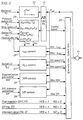
- Figure 2 shows a summary of the controls and limiting signals which are included in the air flow control system.
- Figure 3 shows the configuration of the selection system which determines what control is to be switched on.
- Figure 1 shows the parts of a PFBC plant which constitute the most important components of an air flow system, as largely described also in the above-mentioned patent documents.
- Numeral 1 designates a combustor inside a pressure vessel 2. Air is sucked into the low-pressure compressor 3 and passes through an intermediate cooler 4 on its way to a high-pressure compressor 5. From there the air is passed into the pressure vessel 2. The gas outlet from the combustor is passed via cyclones (not shown) to a high-pressure turbine 6 and on its way out into the free environment the gas passes through a low-pressure turbine 7.
- the figure also shows a storage vessel 8 with bed material for adjustment of the bed level "h" in connection with load changes. Fuel is intended to be injected at the inlets 9.
- an electric machine 10 which upon start-up may operate as a motor and which in normal operation may operate as a generator. Output of power from tubes present in the bed is not shown in the figure.
- An air flow control according to the invention comprises a new concept for such a control since as executive member in the air flow control there is used a guide vane ring 11 which adjustable guide vanes on the input side of the low-pressure turbine. This means that the air flow is regulated by influencing the gas flow by means of the guide vane ring.
- the guide vane ring is the same as that which according to SE 8602003-9 (US-A-4893466) is used as executive member for power control of the electric generator included therein.
- the operating member of the guide vane ring is shown at 12 and this member is influenced by the PID-connected air flow regulator 13.
- the air flow control has a set value, G set , and an actual value, G actual .
- the air flow is normally measured in kg/s.
- N n N H 416/T3
- N H the physical speed, that is, the speed measured directly on the high-pressure shaft
- T 3 the temperature of the air in kelvin before the high-pressure compressor.
- the normalized compressor air flow G N as a function of the pressure ratio P 4 /P 3 across the high-pressure compressor can be determined.
- This function is called ⁇ -value within the current technical field and will come into the picture in a most obvious way in some of the limiting controls which will be described below. Measuring means for these pressures are shown at 18 and 19 in Figure 1.
- the speed N LC of the low-pressure unit must not be below a given minimum value or above a certain maximum value.
- the measured value for this speed is included in the limiting control which continuously ensures that the speed lies within permissible limits.
- the measured value is obtained by a measured value transducer shown at 20 in Figure 2.
- the limiting controls also comprise the difference pressure between the pressure vessel and the combustor. A measured value of this difference pressure DP may be obtained with the difference pressure gauge 21.
- Figure 1 also shows a so-called intercept valve 22 through which the air flow to the pressure vessel and the gas flow from the combustor can be influenced.
- intercept valve 22 through which the air flow to the pressure vessel and the gas flow from the combustor can be influenced. The task of the value will be explained in greater detail below under the description of the embodiments.
- the different control limitations such as the ⁇ -control, the speed control of the low-pressure compressor, the difference pressure control etc. are included together with the main control with the PID-connected air flow regulator in a selection system according to the invention and the output signal of which corresponds to the most predominant of the controls and which is the signal which is finally supplied to the operating device 11 according to Figure 1 for control of the adjustable guide vanes of the guide vane ring.
- the selection system works with analog signals when it comes to deciding what control is to be switched on.
- the selection system comprises logic signals which are related to the switching on and off of the air flow control, start-up and run-down of the plant as well as various faults which may occur. The configuration of the selection system will be described in greater detail under the description of the embodiment.
- the output signal from the selection system that is, the control signal to the executive member, independently of what control is switched on, is fed back to all the control systems as a follow-up set value which ensures that the outputs of all the regulators have an output signal which only by a given small margin differs from the output of that regulator which is switched on.
- Figure 2 shows a summary of the measurement and control signals which are included in the air flow control and the limiting controls which are associated therewith.
- a description is given of how both the set value and the actual value for the air flow control are produced. The production of these quantities are therefore shown only symbolically in Figure 2 in the form of the set value calculator 23 and the actual value calculator 24.
- Input signal to the set value transducer is, in the example shown, the bed level "h" which is assumed to have been produced in some known way, for example via the pressure difference measurement between P ⁇ and P B as previously described.
- the determination of the actual value for the air flow is performed, as mentioned above, with the aid of measured values for pressure upstream and downstream of the high-pressure compressor, the temperature downstream of the high-pressure compressor and the speed of the high-pressure unit, which values are supplied to the actual value calculator which, with access to stored characteristics for normalized air flow of the high-pressure compressor for different ⁇ -values for normalized speeds thereof, may supply an actual value for air flow.
- FIG 2 also shows the PID-connected air flow regulator 13 according to Figure 1.
- the output of the regulator that is, the control signal to the operating member of the guide vane if this control is switched on, is supplied to the selection system 25 which will be described in detail below.
- the selection system determines which control system is to be switched on and the output signal from the selection system is supplied to the operating device 11 of the guide vane according to Figure 1.
- each control will be supplied with a follow-up set value Fset, as described above and shown in Figure 2, which continuously ensures that each control system receives a control output signal which differs, by a small deviation only, from the control signal which is activated.
- this control is based on a ⁇ -surging limit curve which lies below the actual limit curve for surging and a ⁇ -choking limit curve which lies above the actual limit curve for choking.
- this control has as input signal the ⁇ HC -value and the normalized speed N N of the high-pressure compressor, which both values are obtained in connection with the production of the actual value for the air flow control as well as the pressure after the high-pressure compressor.
- the ⁇ HC -control comprises two regulators, one of which supplies a control signal "Min ⁇ " and the other a control signal "Max ⁇ " which, when the operating state starts to approach the respective limit regions, exert an influence on the air flow control in such a way that these signals, via the selection system, are determining for the position of the guide vane ring.
- the ⁇ HC -regulators are supplied with the follow-up set value F set to avoid disturbing jerks in the control when any of these controls is switched on.
- the Max- ⁇ regulator then sees to it that a set value for the Max- ⁇ control is generated which has such a value that the working point of the compressor by a certain margin does not come too close to the ⁇ -surging limit curve, that is, lies below the ⁇ -surging limit curve.
- a maximum curve is assumed which is determined by a curve equal to 0.9 times the ⁇ -surging limit curve.
- the Min- ⁇ regulator provides a set value for Min- ⁇ control when an operating position approaching the region for choking is about to be obtained.
- a margin in relation to the ⁇ -choking limit curve has been selected which is dependent on the pressure after the high-pressure compressor, that is, P 4 , and for that reason also a measured value for this pressure is supplied to the ⁇ -regulator.
- a certain pressure for example 3.5 bar
- a Min- ⁇ value is used which is determined by the ⁇ -choking limit curve and when the pressure is lower, a curve which is a few per cent lower than the ⁇ -choking limit curve is used.
- this value also permits a satisfactory margin in relation to the actual choking limit curve.
- the low-pressure unit is not allowed to operate at speeds below a certain minimum speed or above a certain maximum speed. If there are tendencies in that direction, the limitation is to take over the control of the guide vane ring via the selection system.
- the measured value for the speed of the low-pressure unit is therefore supplied to the N LC control 27 in Figure 2. From there a signal "Minspeed LC” is obtained if the actual speed drops to the lowest permissible speed and a signal “Maxspeed LC” is obtained if the speed is increased to the highest permissible.
- One of these signals will determine the mode of running of the air flow system via the selection system if this signal is the predominant one of all control signals. As is clear from the figure, also this control is supplied with the follow-up set value F set .
- an electric machine 10 is connected to the shaft of the high-pressure unit.
- this machine operates as a generator and delivers electrical power to the power network.
- the same machine may also advantageously be used as a motor for start-up of the high-pressure unit and then draws power from the network.
- the power from the network to the machine operating as a motor must be limited. A measured value of this power is therefore supplied to a maximum power control 28 according to Figure 2. This control operates in exactly the same way as the DP control.
- the air flow which is supplied to the pressure vessel tends to give this vessel an overpressure in relation to the combustor.
- the difference pressure must be limited to a maximum value and the measured value DP of the difference pressure DP, obtained with the aid of the transducer 21 according to Figure 1, is therefore supplied to the difference pressure control 29 according to Figure 2.
- This control operates in the same way as the other control systems in that the output signal, for as long as the difference pressure is below a permissible maximum value set in advance with a certain margin, because of the follow-up set value delivers a signal which follows the signal which is currently switched on.
- the DP control delivers a "Max DP" signal which, if the other conditions are fulfilled, is allowed to determine the movement of the guide vanes via the selection system.
- the maximum permissible difference pressure in a plant designed according to the invention has been set at 0.55 bar.
- the status of the fuel injection concerns the operating state of the whole PFBC plant and information about the condition (FO) must therefore be supplied to the selection system.
- GT trip a function called GT trip. Upon a GT trip, special measures must be taken and it is therefore important that the selection system is informed of this (GT).
- the high-pressure unit is driven by the electric machine, connected to the common shaft and fed from the network. Only when the speed of the unit has reached the speed which corresponds to the necessary speed to be able to phase the machine into the network, is it opened for air supply to the pressure chamber and also for gas outlet from the combustor. This opening is performed with the intercept valve 22 according to Figure 1. It is therefore important for the selection system to know whether the intercept valve has opened or not (IO).
- the selection system 25 can be designed in a plurality of different ways depending on the desired control and protection strategy and whether input and output signals are analog and/or digital signals.
- the selection system may also be built up in a more or less integrated form within the scope of the invention.
- a preferred embodiment is shown in Figure 3. Since the input signals in the described embodiment consist of both analog and digital signals, the selection system must comprise both analog and digital selectors for the logic decisions that are to be made. All the digital selectors in Figure 3 are drawn in a position in which the activation signal from the logic inputs are 0.
- Selector V1 is a first minimum selector whose output signal U1 is the smaller of the control signal and the signal Minspeed LC.
- the output signal is passed to a maximum selector V2 whose output signal U2 consists of that of the input signals thereto which is the greater.
- D1 is not activated
- the first digital selector is activated, as is clear from Figure 3, by the signal Fuel injection when this changes from 0 to 1.
- U3 will then be equal to a Max MW signal filtered in the filter F and U4 will be equal to the Max DP signal.
- the output sicnal from V3, that is U5 according to Figure 3 consists of the control signal which is passed to the operating device of the guide wave unless the logical signals from Intercept or GT trip are activated and request otherwise.
- the output signal U6 from D3, because the reference a4 of D2 corresponds to the maximum control signal to the operating device of the guide vane, will thus be guided towards an open guide vane ring. In such a state the control signal U5 to the operating device will be disconnected. If D3 is activated, that is, if a GT trip is obtained, the output signal U6 from D3, because of the feedback according to the figure, will retain the value of the signal prevailing prior to the activation independently of the state of D2. As is clear, the signal U5 also forms the follow-up set value F set .
- the activation state of the digital selector D2 is determined by the logical signals from Intercept and GT trip. As is clear from the figure, these signals are passed to a memory M with a subsequent time lag element T. The relationship between the input signals to the S- and R-inputs on the memory and its output is clear from the following summary: Intercept signal S 0 1 0 1 GT trip R 0 0 1 1 M signal M1 0 1 0 0 0
Landscapes
- Engineering & Computer Science (AREA)
- Chemical & Material Sciences (AREA)
- Combustion & Propulsion (AREA)
- Mechanical Engineering (AREA)
- General Engineering & Computer Science (AREA)
- Physics & Mathematics (AREA)
- Fluid Mechanics (AREA)
- Control Of Positive-Displacement Air Blowers (AREA)
- Engine Equipment That Uses Special Cycles (AREA)
- Fluidized-Bed Combustion And Resonant Combustion (AREA)
Applications Claiming Priority (3)
| Application Number | Priority Date | Filing Date | Title |
|---|---|---|---|
| SE9102651 | 1991-09-13 | ||
| SE9102651A SE469039B (sv) | 1991-09-13 | 1991-09-13 | Foerfarande vid luftfloedesreglering i en pfbc-anlaeggning samt anordning foer genomfoerande av foerfarandet. |
| PCT/SE1992/000595 WO1993006351A1 (en) | 1991-09-13 | 1992-08-31 | Air flow control system in pfbc plants |
Publications (2)
| Publication Number | Publication Date |
|---|---|
| EP0603327A1 EP0603327A1 (en) | 1994-06-29 |
| EP0603327B1 true EP0603327B1 (en) | 1997-04-16 |
Family
ID=20383715
Family Applications (1)
| Application Number | Title | Priority Date | Filing Date |
|---|---|---|---|
| EP92920604A Expired - Lifetime EP0603327B1 (en) | 1991-09-13 | 1992-08-31 | Air flow control system in pfbc plants |
Country Status (9)
| Country | Link |
|---|---|
| US (1) | US5457952A (da) |
| EP (1) | EP0603327B1 (da) |
| JP (1) | JP3243252B2 (da) |
| DE (1) | DE69219140T2 (da) |
| DK (1) | DK0603327T3 (da) |
| ES (1) | ES2103381T3 (da) |
| FI (1) | FI941176A7 (da) |
| SE (1) | SE469039B (da) |
| WO (1) | WO1993006351A1 (da) |
Families Citing this family (6)
| Publication number | Priority date | Publication date | Assignee | Title |
|---|---|---|---|---|
| SE505570C2 (sv) * | 1995-12-11 | 1997-09-15 | Abb Carbon Ab | Kraftanläggning |
| SE509987C2 (sv) * | 1995-12-11 | 1999-03-29 | Abb Carbon Ab | PFBC-kraftanläggning |
| SE508085C2 (sv) * | 1996-12-12 | 1998-08-24 | Abb Carbon Ab | Förfarande för luftflödesstyrning av förbränningsluft samt spärrluftanordning |
| JP2012515296A (ja) * | 2009-01-15 | 2012-07-05 | サルガス アーエス | 流動床燃焼の改良 |
| US10811884B2 (en) * | 2018-03-16 | 2020-10-20 | Uop Llc | Consolidation and use of power recovered from a turbine in a process unit |
| US20200340409A1 (en) * | 2019-04-24 | 2020-10-29 | Viettel Group | System and method for gas turbine engine control |
Family Cites Families (7)
| Publication number | Priority date | Publication date | Assignee | Title |
|---|---|---|---|---|
| SE404948B (sv) * | 1977-03-25 | 1978-11-06 | Stal Laval Turbin Ab | Tvaaxlig gasturbinanleggning |
| GB2126382B (en) * | 1982-08-10 | 1986-01-08 | Nissan Motor | Gas turbine engine control system |
| US4530207A (en) * | 1983-05-05 | 1985-07-23 | Asea-Stal Ab | Power plant with a fluidized bed combustion chamber |
| SE452179B (sv) * | 1986-02-20 | 1987-11-16 | Asea Stal Ab | Forfarande samt anordning for styrning av en pfbc-anleggning |
| SE453114B (sv) * | 1986-04-29 | 1988-01-11 | Asea Stal Ab | Sett for drift av ett turbinaggregat |
| US5193337A (en) * | 1988-07-25 | 1993-03-16 | Abb Stal Ab | Method for operating gas turbine unit for combined production of electricity and heat |
| SE9000603D0 (sv) | 1990-02-20 | 1990-02-20 | Abb Stal Ab | Saett och anordning foer att reglera effektuttag fraan foerbraenning i virvelbaedd |
-
1991
- 1991-09-13 SE SE9102651A patent/SE469039B/sv not_active IP Right Cessation
-
1992
- 1992-08-31 DE DE69219140T patent/DE69219140T2/de not_active Expired - Lifetime
- 1992-08-31 EP EP92920604A patent/EP0603327B1/en not_active Expired - Lifetime
- 1992-08-31 WO PCT/SE1992/000595 patent/WO1993006351A1/en not_active Ceased
- 1992-08-31 US US08/204,406 patent/US5457952A/en not_active Expired - Lifetime
- 1992-08-31 DK DK92920604.3T patent/DK0603327T3/da active
- 1992-08-31 JP JP50598493A patent/JP3243252B2/ja not_active Expired - Lifetime
- 1992-08-31 ES ES92920604T patent/ES2103381T3/es not_active Expired - Lifetime
-
1994
- 1994-03-11 FI FI941176A patent/FI941176A7/fi unknown
Also Published As
| Publication number | Publication date |
|---|---|
| SE469039B (sv) | 1993-05-03 |
| US5457952A (en) | 1995-10-17 |
| DK0603327T3 (da) | 1997-10-27 |
| SE9102651L (sv) | 1993-03-14 |
| DE69219140D1 (de) | 1997-05-22 |
| FI941176A0 (fi) | 1994-03-11 |
| DE69219140T2 (de) | 1997-11-13 |
| FI941176A7 (fi) | 1994-03-11 |
| JP3243252B2 (ja) | 2002-01-07 |
| EP0603327A1 (en) | 1994-06-29 |
| SE9102651D0 (sv) | 1991-09-13 |
| ES2103381T3 (es) | 1997-09-16 |
| JPH06510833A (ja) | 1994-12-01 |
| WO1993006351A1 (en) | 1993-04-01 |
Similar Documents
| Publication | Publication Date | Title |
|---|---|---|
| EP0661426B1 (en) | Gas turbine apparatus and method of operating same | |
| US4716719A (en) | Method of and apparatus for controlling fuel of gas turbine | |
| EP0377292B1 (en) | Integrated boost compressor/gas turbine control system | |
| US5083277A (en) | Fuel control system | |
| EP0761948B1 (en) | Fuel control system for gas turbine engine | |
| CN114051555B (zh) | 确定用于在飞行器发动机的燃料供给回路中计量燃料的燃料密度的方法 | |
| US7556473B2 (en) | Control unit for compressor | |
| US7269953B2 (en) | Method of controlling a power generation system | |
| US6619027B1 (en) | Gas turbine having rotor overspeed and overboost protection | |
| US4344141A (en) | Gas-turbine engine control | |
| KR20050056939A (ko) | 개선된 연료 운반 시스템 | |
| EP0005135A1 (en) | Exhaust nozzle control and core engine fuel control for turbofan engine | |
| KR840000920B1 (ko) | 유동 또는 일정 압력보일러용 터빈 제어시스템 | |
| EP0603327B1 (en) | Air flow control system in pfbc plants | |
| EP0081377B1 (en) | Control systems for power plant feedwater systems | |
| US4603394A (en) | Microprocessor-based extraction turbine control | |
| US6915639B1 (en) | Method and apparatus for gas turbine over-speed protection | |
| US4878348A (en) | Turbine governor valve monitor | |
| US4773213A (en) | Engine control with smooth transition to synthesized parameter | |
| US20240026825A1 (en) | Two stage fuel delivery system for an aircraft | |
| JPS63150435A (ja) | ガスタービンエンジンの制御装置及び方法 | |
| US3695038A (en) | Installation or plant control device, in particular for gas-turbine power plants | |
| US4976108A (en) | Turbine efficient valve position computer | |
| US11725593B2 (en) | Gas turbine and method for adjusting flow rate of fuel supplied thereto | |
| GB2315100A (en) | Fuel regulator for turbojet engines |
Legal Events
| Date | Code | Title | Description |
|---|---|---|---|
| PUAI | Public reference made under article 153(3) epc to a published international application that has entered the european phase |
Free format text: ORIGINAL CODE: 0009012 |
|
| 17P | Request for examination filed |
Effective date: 19940322 |
|
| AK | Designated contracting states |
Kind code of ref document: A1 Designated state(s): DE DK ES FR GB IT |
|
| 17Q | First examination report despatched |
Effective date: 19950523 |
|
| GRAG | Despatch of communication of intention to grant |
Free format text: ORIGINAL CODE: EPIDOS AGRA |
|
| GRAH | Despatch of communication of intention to grant a patent |
Free format text: ORIGINAL CODE: EPIDOS IGRA |
|
| GRAH | Despatch of communication of intention to grant a patent |
Free format text: ORIGINAL CODE: EPIDOS IGRA |
|
| GRAA | (expected) grant |
Free format text: ORIGINAL CODE: 0009210 |
|
| AK | Designated contracting states |
Kind code of ref document: B1 Designated state(s): DE DK ES FR GB IT |
|
| REF | Corresponds to: |
Ref document number: 69219140 Country of ref document: DE Date of ref document: 19970522 |
|
| ET | Fr: translation filed | ||
| PGFP | Annual fee paid to national office [announced via postgrant information from national office to epo] |
Ref country code: DK Payment date: 19970815 Year of fee payment: 6 |
|
| REG | Reference to a national code |
Ref country code: ES Ref legal event code: FG2A Ref document number: 2103381 Country of ref document: ES Kind code of ref document: T3 |
|
| REG | Reference to a national code |
Ref country code: DK Ref legal event code: T3 |
|
| PLBE | No opposition filed within time limit |
Free format text: ORIGINAL CODE: 0009261 |
|
| STAA | Information on the status of an ep patent application or granted ep patent |
Free format text: STATUS: NO OPPOSITION FILED WITHIN TIME LIMIT |
|
| 26N | No opposition filed | ||
| PG25 | Lapsed in a contracting state [announced via postgrant information from national office to epo] |
Ref country code: DK Free format text: LAPSE BECAUSE OF NON-PAYMENT OF DUE FEES Effective date: 19980831 |
|
| REG | Reference to a national code |
Ref country code: GB Ref legal event code: IF02 |
|
| REG | Reference to a national code |
Ref country code: DK Ref legal event code: EBP |
|
| PGFP | Annual fee paid to national office [announced via postgrant information from national office to epo] |
Ref country code: DE Payment date: 20110831 Year of fee payment: 20 Ref country code: GB Payment date: 20110722 Year of fee payment: 20 Ref country code: FR Payment date: 20110811 Year of fee payment: 20 Ref country code: ES Payment date: 20110804 Year of fee payment: 20 |
|
| PGFP | Annual fee paid to national office [announced via postgrant information from national office to epo] |
Ref country code: IT Payment date: 20110816 Year of fee payment: 20 |
|
| REG | Reference to a national code |
Ref country code: DE Ref legal event code: R071 Ref document number: 69219140 Country of ref document: DE |
|
| REG | Reference to a national code |
Ref country code: DE Ref legal event code: R071 Ref document number: 69219140 Country of ref document: DE |
|
| REG | Reference to a national code |
Ref country code: GB Ref legal event code: PE20 Expiry date: 20120830 |
|
| PG25 | Lapsed in a contracting state [announced via postgrant information from national office to epo] |
Ref country code: GB Free format text: LAPSE BECAUSE OF EXPIRATION OF PROTECTION Effective date: 20120830 Ref country code: DE Free format text: LAPSE BECAUSE OF EXPIRATION OF PROTECTION Effective date: 20120901 |
|
| REG | Reference to a national code |
Ref country code: ES Ref legal event code: FD2A Effective date: 20130711 |
|
| PG25 | Lapsed in a contracting state [announced via postgrant information from national office to epo] |
Ref country code: ES Free format text: LAPSE BECAUSE OF EXPIRATION OF PROTECTION Effective date: 20120901 |