EP0603350B1 - Flüssigkeitsfühler für verkaufsautomat - Google Patents
Flüssigkeitsfühler für verkaufsautomat Download PDFInfo
- Publication number
- EP0603350B1 EP0603350B1 EP93911021A EP93911021A EP0603350B1 EP 0603350 B1 EP0603350 B1 EP 0603350B1 EP 93911021 A EP93911021 A EP 93911021A EP 93911021 A EP93911021 A EP 93911021A EP 0603350 B1 EP0603350 B1 EP 0603350B1
- Authority
- EP
- European Patent Office
- Prior art keywords
- moisture
- vending machine
- power
- tray
- circuit
- Prior art date
- Legal status (The legal status is an assumption and is not a legal conclusion. Google has not performed a legal analysis and makes no representation as to the accuracy of the status listed.)
- Expired - Lifetime
Links
- 239000007788 liquid Substances 0.000 title claims abstract description 41
- 238000001514 detection method Methods 0.000 claims abstract description 30
- 239000012530 fluid Substances 0.000 claims abstract description 25
- 238000000034 method Methods 0.000 claims abstract description 21
- 230000006378 damage Effects 0.000 claims abstract description 18
- 230000000994 depressogenic effect Effects 0.000 claims abstract description 9
- 230000007246 mechanism Effects 0.000 claims description 21
- 230000035945 sensitivity Effects 0.000 claims description 6
- 230000003044 adaptive effect Effects 0.000 claims description 3
- 239000002184 metal Substances 0.000 claims description 3
- 230000007613 environmental effect Effects 0.000 claims 1
- 239000002991 molded plastic Substances 0.000 claims 1
- 238000012544 monitoring process Methods 0.000 claims 1
- 238000009938 salting Methods 0.000 abstract description 40
- 239000003990 capacitor Substances 0.000 description 17
- 230000008859 change Effects 0.000 description 11
- 239000004033 plastic Substances 0.000 description 9
- 238000004140 cleaning Methods 0.000 description 4
- 238000010586 diagram Methods 0.000 description 4
- 230000009471 action Effects 0.000 description 3
- 230000001965 increasing effect Effects 0.000 description 3
- 239000000463 material Substances 0.000 description 3
- 230000036961 partial effect Effects 0.000 description 3
- 230000008439 repair process Effects 0.000 description 3
- 230000003247 decreasing effect Effects 0.000 description 2
- 230000000881 depressing effect Effects 0.000 description 2
- 238000013461 design Methods 0.000 description 2
- 239000011888 foil Substances 0.000 description 2
- 230000005484 gravity Effects 0.000 description 2
- 238000009434 installation Methods 0.000 description 2
- 230000001052 transient effect Effects 0.000 description 2
- XLYOFNOQVPJJNP-UHFFFAOYSA-N water Substances O XLYOFNOQVPJJNP-UHFFFAOYSA-N 0.000 description 2
- 235000014676 Phragmites communis Nutrition 0.000 description 1
- CDBYLPFSWZWCQE-UHFFFAOYSA-L Sodium Carbonate Chemical compound [Na+].[Na+].[O-]C([O-])=O CDBYLPFSWZWCQE-UHFFFAOYSA-L 0.000 description 1
- 230000002159 abnormal effect Effects 0.000 description 1
- 230000000712 assembly Effects 0.000 description 1
- 238000000429 assembly Methods 0.000 description 1
- 230000015556 catabolic process Effects 0.000 description 1
- 230000005465 channeling Effects 0.000 description 1
- 230000009194 climbing Effects 0.000 description 1
- 230000007797 corrosion Effects 0.000 description 1
- 238000005260 corrosion Methods 0.000 description 1
- 230000001066 destructive effect Effects 0.000 description 1
- 230000000694 effects Effects 0.000 description 1
- 238000001914 filtration Methods 0.000 description 1
- 230000001939 inductive effect Effects 0.000 description 1
- 230000002401 inhibitory effect Effects 0.000 description 1
- 238000003780 insertion Methods 0.000 description 1
- 230000037431 insertion Effects 0.000 description 1
- 238000009413 insulation Methods 0.000 description 1
- 239000012212 insulator Substances 0.000 description 1
- 230000000670 limiting effect Effects 0.000 description 1
- 238000005259 measurement Methods 0.000 description 1
- 230000004048 modification Effects 0.000 description 1
- 238000012986 modification Methods 0.000 description 1
- 230000002829 reductive effect Effects 0.000 description 1
- 230000000246 remedial effect Effects 0.000 description 1
- 230000000717 retained effect Effects 0.000 description 1
- 230000002441 reversible effect Effects 0.000 description 1
- 239000013535 sea water Substances 0.000 description 1
- 238000000926 separation method Methods 0.000 description 1
- 230000007480 spreading Effects 0.000 description 1
- 239000000758 substrate Substances 0.000 description 1
- 238000010200 validation analysis Methods 0.000 description 1
Images




Classifications
-
- G—PHYSICS
- G07—CHECKING-DEVICES
- G07F—COIN-FREED OR LIKE APPARATUS
- G07F7/00—Mechanisms actuated by objects other than coins to free or to actuate vending, hiring, coin or paper currency dispensing or refunding apparatus
- G07F7/005—Details or accessories
-
- G—PHYSICS
- G07—CHECKING-DEVICES
- G07F—COIN-FREED OR LIKE APPARATUS
- G07F1/00—Coin inlet arrangements; Coins specially adapted to operate coin-freed mechanisms
- G07F1/04—Coin chutes
- G07F1/041—Coin chutes with means, other than for testing currency, for dealing with inserted foreign matter, e.g. "stuffing", "stringing" or "salting"
- G07F1/045—Coin chutes with means, other than for testing currency, for dealing with inserted foreign matter, e.g. "stuffing", "stringing" or "salting" the foreign matter being in the form of liquids
Definitions
- the present invention relates generally to an apparatus and method for reducing vandalism and minimizing damage to a vending machine from injected fluids.
- This invention is concerned with means for increasing the ability of vending machine components, specifically bill validators, to handle an increased volume of injected fluids.
- the liquids injected into a vending machine opening can cause extensive damage to the component associated with that opening.
- the liquids may drip into other machine components and cause direct or indirect damage, increasing the cost of repair.
- the moisture sensor circuitry operates to remove power to the validator and to provide an alarm function when liquids are sensed.
- the bill validator must be disassembled for installation of the unit, and when moisture is sensed the vend line is not disconnected. Further, the unit does little to reduce the collateral damage produced by a salting attack.
- the moisture sensor of this unit is potentially exposed to tampering. Yet further, cleanup requires access to the moisture sensor.
- Vender Defender which is a shield-type device for limiting the amount of fluid injected into the entrance of a bill validator. This unit does nothing to remove power or provide other protection in the case of a salting attack.
- US-A-4346798 discloses a coin hopper for use on vending machines in which a downwardly slanting support surface is provided to divert liquid away from the coin hopper entrance and into a reservoir. Thus, liquid is prevented from entering the coin changer, thus avoiding dangerous electrical conditions.
- JP-A-1-250189 appears to show a vending machine with a moisture sensor comprising a pair of electrodes located in a downwardly slanting inclined coin ramp surface.
- the invention provides an apparatus for connection to an international component of a vending machine according to claim 1.
- the invention provides a method for preventing fraud and for minimizing damage from a liquid injected into a vending machine according to claim 22.
- the anti-salting module of the present invention provides protection to bill validators and other vending machine components from insertion of conductive fluids into vending machine apertures.
- the anti-salting module consists of two parts, the first is the module itself which includes a T-cable for electronic connection, and the second is a rubber fillet which fits in the rear of the bill validator beneath a bill stacker.
- the fillet is designed to reduce the amount of liquids retained by the bill validator, and acts to direct injected fluids toward a moisture sensor in the anti-salting module to make detection easier.
- the anti-salting module is mounted external to the bill validator without the need to use additional hardware or to modify the bill validator.
- the module contains tabs or fingers and clips which connect to existing openings located beneath the bill validator.
- the anti-salting module can be attached to the bill validator without using any tools, and remains in place under the influence of gravity.
- a T-cable electronically connects the module to the ends of the cables from the bill validator and the coin mechanism.
- the anti-salting module has an integral tray to collect injected fluids and to direct them towards a drain.
- the drain accepts 1 inch diameter tubing which can be used to direct the injected liquid away from the vending machine components.
- An integral moisture sensor is located in the tray, and detection and control electronics are connected to the sensor. Other moisture sensors may be located in other parts of the vending machine and connect to the detection and control electronics of the module. Further, a continuity sensor and associated detection circuitry may be used to monitor status of other vending machine components.
- a set of alarm contacts are available to the vending machine owner which can be used to sound an alarm or siren, disable the machine dispensers, or turn off the vending machine entirely.
- the tray of the anti-salting module After a salting attack, the tray of the anti-salting module must be cleaned before the bill validator can be repowered. An LED in the module, which lights when moisture is detected by the moisture sensor, aids in this cleaning operation. Once this LED is no longer on, then the unit can be returned to service by depressing the SET switch.
- Fig. 1 depicts an embodiment of the anti-salting module 1 and fillet 5 of the present invention. This embodiment is designed for use with a Mars Electronics International model VFM1 and VFM3 bill validator. It should be understood that other embodiments would be required for other models and for attachment to bill validators manufactured by other companies.
- the anti-salting module 1 has a receptical, cup or tray 2 for collecting fluids.
- the tray 2 is an integral portion of the module 1 and is formed into this shape when the plastic body which constitutes the module 1 is molded.
- the tray 2 contains a drain 3 and an integral moisture sensor 4, and is shaped so that fluids that would normally drip onto various vending machine components mounted beneath the bill validator, such as the coin mechanism, cash box, and vend switches, are directed over the moisture sensor 4 and to the drain 3.
- the moisture sensor 4 is comprised of two conductive strips or electrodes mounted into depressions in the tray 2. Detector circuitry (not shown) senses a change in resistance across the narrow portion of plastic between the electrodes when a conductive fluid is introduced. Thus, when a conductive fluid or moisture is detected in the tray 2, the detector circuitry acts to disconnect power and control signals as described below.
- the anti-salting module 1 has extensions or fingers 6 which are designed to slip into vertical openings between the mounting bezel and the body of a bill validator (shown in Figs. 2, 3 and 4). Shaped wire clips 8, mounted to the rear of the module 1, are designed to slip into existing openings in the rear of the bill validator. When connected, the anti-salting module 1 is secured to the bottom of a bill validator under the influence of gravity.
- the fillet 5 is a molded piece of rubber designed to fit into the rear of the bill validator beneath a bill stacker.
- the fillet 5 directs injected fluids into the tray 2, and is discussed below with reference to Fig. 4.
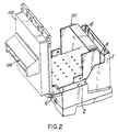
- Fig. 2 depicts the anti-salting module 1 attached to a partial bill validator assembly 101.
- a face plate or bezel 102 has a bill opening 104 through which conductive fluids are injected by vandals. (Like components are numbered the same in the figures.)
- Various bill validator mechanisms such as the bill transport and validation system, have been removed to show the various openings through which fluids would flow into the tray 2, and to illustrate how the anti-salting module 1 is connected. As shown, fingers 6 and wire clips 8 attach to existing openings of the assembly 101.
- Fig. 3 depicts the assembly of Fig. 2 rotated 90 degrees to show the underside of the anti-salting module 1.
- An electronics compartment 10 having a cover 11 is shown.
- the electronics compartment 10 holds the moisture detection and control circuitry in an enclosed area located below the tray 2.
- a moisture present LED 82 and a SET switch 84 are also shown, and are discussed in detail below.
- the drain 3 can accept one inch diameter flexible tubing to allow collected liquids to be piped into an area where they will do no harm.
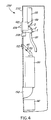
- Fig. 4 is a partial cutaway side view, not drawn to scale, of a vending machine 200 showing a typical component layout along the vending machine front panel 210.
- Fig. 4 also shows the anti-salting module 1 and fillet 5 connected to the bill validator 100.
- the anti-salting module 1 and fillet 5 can be fitted to existing bill validators without the use of additional hardware, and without modifying or removing the existing validator from the front panel 210.
- the front panel 210 contains bill validator bezel 102, a bill opening 104, exact change light 108, coin slot 152 and coin return chute 154, which are accessible to customers of the vending machine.
- the module 1 mounts directly beneath the bill validator 100 inside the vending machine 200, and is accessible only to service personnel, not to customers using the vending machine.
- Plastic tubing 20 is connected to the module 1, and is used to drain fluids collected in the tray 2 away from the vending machine components to a bucket or some other drainage means (not shown).
- the tubing 20 could be made of rubber, plastic or other materials and comprise tubing, pipe or any other type of conduit for channeling the liquid.
- a coin mechanism 150 is also shown having a coin slot 152, coin track 153 and a coin return chute 154, and is mounted above the cash box 160.
- An external moisture sensor 45 can be placed in the coin track 153, and is electronically connected to the detection circuitry of the module 1, as explained below.
- the fillet 5 of the present invention is inserted into the rear of the bill validator 100 under the bill stacker 110, as shown, to block fluid from flowing into the validator.
- the fillet 5 also directs fluids into the tray 2 to trigger the moisture sensor 4, and for draining liquid away from other sensitive circuitry.
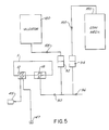
- Fig. 5 is a simplified block diagram showing the electrical connections of the anti-salting module 1 depicted in Fig. 4.
- the module 1 is connected via a T-cable 30 and two 9-pin connectors 32, 34 to the bill validator 100 and the coin mechanism 150.
- the coin mechanism 150 is normally connected directly to the bill validator 100, via cables 105 and 155, to provide power to the validator and to permit the exchange of signals.
- the bill validator 100 and coin mechanism 150 plug directly into the anti-salting module 1.
- a power supply is integral to the anti-salting module 1 and is powered from AC power obtained from the coin mechanism cable 155.
- the electronic control circuitry for the anti-salting module 1 is mounted in an electronics compartment 10 (shown in Fig. 3) located beneath the tray 2. Both strips of metal which comprise the moisture sensor 4 are connected to a PC board (shown in Fig. 3) by a screw or stud (not shown) which passes vertically through the floor of the tray 2 and into the electronics compartment 10. The bottom of the tray 2 remains sealed. Thus, the PC board and electronic circuitry in the electronics compartment 10 of the anti-salting module 1 are protected from liquids (See Figs. 1 and 3).
- a 14-pin connector 18 allows for connections of the T-cable 30 to both the coin mechanism 150 and the bill validator 100 of Figs. 4 and 5.
- a 4-pin connector 12 allows other functions to be added to the vending machine 200 for added protection.
- another moisture sensor 45 could be added elsewhere in the machine, or a continuity sensor 47 could be added to detect if any components, panels, or assemblies in the vending machine 200 were moved or damaged in any way.
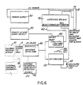
- Fig. 6 is a block diagram of an embodiment of the circuitry of the anti-salting module 1.
- a power supply 50 supplies 12 volts of power through a transformer (shown in Fig. 7A), and isolates the electronics from AC power so that power leakage will not occur in the presence of liquids.
- a moisture detector 40 is connected to the electrodes of the moisture sensor 4 mounted in the bottom of the tray 2. The output of the moisture detector 40 goes high if moisture or a conductive liquid is sensed.
- An external moisture sensor 45 can also be connected to the moisture detector 40 to monitor for moisture in another part of the vending machine.
- a continuity alarm 43 can also activate the moisture detector 40 if an external continuity device 47 in the vending machine 200 senses a change in state of another part of the vending machine, such as damage to a front door assembly. This can be used to ensure integrity of other vending machine functions that may suffer from tampering.
- Reset circuitry 60 accepts the output of the moisture detector 40 and generates a single 20ms or greater pulse when this level goes from a low, approximately one volt or lower, to high, typically 10 volts or higher.
- This pulse is delivered via line 62 to the reset coils of three latching relays (shown in Fig. 7A) in latching relays block 70, whose set and reset coils are connected in parallel.
- Each relay will latch in one position and remain there even in the absence of power, remembering the state into which they were last driven.
- the reset coils of the latching relays are powered momentarily, latching them in the reset position. Five of six sets of latching relay contacts are used to remove AC power and control lines from the validator.
- the sixth set of contacts can be used to inhibit machine operation, to disable the coin mechanism from paying out coins, to operate an alarm or timed siren, to remove power from the entire vending machine, or a combination of these.
- the latched unpowered state can render the entire machine inoperable. This allows the operator to become aware of the contaminated state of the machine and initiate remedial action so as to reduce the corrosion to the bill validator, coin mechanism and the vending machine.
- the alarm contacts of the relays are set in the active position. This is called the reset or unpowered state. This is particularly important since having AC power connected to the bill validator in the presence of a conducting liquid is very destructive. Shorts and conduction paths are created both across the AC line and to low voltage circuitry which may cause extensive damage and makes repair very difficult. Removal of power prevents the bill acceptor motor from running and spreading the conductive liquid up into the electronics and bill stacker assembly. Further, the vend relay line is broken (opened by a latching relay), so that no spurious vend pulses can be generated by the bill validator. Thus, the causes of multiple phantom vends are removed which normally result in coins and product being paid out by the vending machine during a salting attack.
- AC line related signals associated with enabling and inhibiting are required to support some bill validator interfaces. These lines are also opened by use of a latching relay. All of these lines, five in number, are broken and then latched in the open state (no AC power, no vend, no control lines) so that removal of AC line power from the vending machine at the wall outlet, and then reapplication of AC line power, cannot cause these contacts to be closed and return the validator to operation. This prevents later damage to the bill validator, perhaps during service and cleanup, as well as prevents the vandal from attempts to re-power the vending machine to obtain product or money.
- the output of the moisture detector 40 also drives the Set block 80.
- the Set block 80 turns on a moisture present LED 82 when moisture is detected.
- it provides the output pulse to drive the set coils of latching relays into the Set or Operate condition when a SET switch 84 is depressed.
- This pushbutton is integral to the module.
- the SET switch 84 When the SET switch 84 is depressed, the contacts of the relays in the unit move to their set position and return normal functionality to the validator only if the moisture detector determines that moisture is no longer present. This ensures that the affected unit is serviced and not just repowered. This can result in a timely repair which will reduce damage to the unit.
- the moisture present LED 82 aids the service technician in the cleaning of the unit.
- Power Up/Down detect circuitry 90 inhibits the Reset circuitry 60 so that the status of the latching relays does not change when AC power is applied or removed from the bill validator, or from the vending machine. This prevents false triggering of the reset coils of the latching relays when AC power is changing.
- Moisture is detected when fluids connect the two electrodes of the moisture sensor 4 which changes the resistance across the electrodes. This occurs because the resistivity value of water and other fluids is much smaller than that of the plastic insulation and air that separates the two electrodes.
- An embodiment of the moisture sensor 4 of the present invention comprises two metal electrodes, each 54mm long, separated by about 2mm of the plastic tray material.
- the plastic has a bulk resistivity of approximately 1.4 to 1.5 x 10 14 ohm/cm.
- the resistance across the electrodes without any liquid present is about 4 x 10 11 ohms.
- Figs. 7A and 7B depict an embodiment of the moisture detection and control circuitry of the present invention.
- the power supply circuitry 50 receives 117VAC power from the coin mechanism 150 via the T-cable 30 which is plugged into the 14-pin connector 18 or P1 on the PC board.
- AC power enters on pins 6 and 7 of P1 and is used to drive the input side of transformer T1.
- AC power leaves P1 via pins 13 and 14 to the bill validator 100 if the relay K2 is in its normal set position.
- Transformer T1 steps down the AC line voltage and isolates the circuitry from the AC line.
- the AC voltage at the secondary of T1 is rectified by the diode bridge D1.
- Capacitor C3 filters the pulsating DC appearing at the input of the voltage regulator U1.
- Capacitors C1 and C2, located on the primary and secondary sides of T1, are used to lower line noise.
- Capacitors C4 and C5 provide filtering of the output of the 12V linear voltage regulator U1.
- the range sensitivity jumper shown in Fig. 7B, is in the normal (JP1) position and jumper JP3 is in place.
- the moisture detection and control circuitry is set to function with normal sensitivity and without a continuity sensor.
- the function of jumpers JP1, JP2 and JP3 is discussed in detail below.
- the moisture detector circuitry 40 uses two sections of a quad LM224 operational amplifier integrated circuit, U2B and U2A.
- U2B is used as a high impedance voltage follower while U2A is used as comparator.
- One of the terminals of the moisture sensor electrodes 4, which is integral to the tray 2 is connected at the junction of resistors R9 and R10.
- the second terminal of the integral moisture sensor 4 is connected to ground.
- the moisture detector forms a voltage divider as a third resistor to ground which is in series with R8 and R9. This is the point that is presented to the noninverting input of U2B via resistor R10. If there is no moisture present across the terminals of the electrodes in the tray 2, the resistance across these terminals will be many megohms in value.
- the input impedance of the voltage follower U2B will be 40 megohms or greater.
- the voltage at the junction of R9 and R10 will be an appreciable fraction of the 12 volt supply, since the impedance at the top of capacitor C8 looking up towards the 12 volt supply is only 1.32 megohms while that looking down towards ground will be many megohms.
- the resistance of the sensor in parallel with the input impedance of U2B is 11 times that of the sum of R8 and R9, then the resistance is approximately 14.5 megohms. This means that the voltage at C8 will be about 11 volts. Since very little current flows into the noninverting input of U2B, then the voltage at the noninverting input (pin 5) will be nearly 11 volts as well.
- the divider R13 and R14 will divide this in half so that the voltage at the noninverting input of the comparator U2A will be approximately 5.9 volts. Since the voltage at the inverting input of U2A is 11 volts, and the inverting input voltage is much greater than the noninverting input, the output of U2A will remain low.
- the impedance across C8 will drop to less than 10K ohms.
- the exact amount the impedance drops depends upon various factors including how much liquid is present, how conductive it is, the area of the sensor involved, and the type and temperature of the liquid. Assuming that the resistance drops to 10K ohms, since resistors R8 and R9 form a voltage divider with the sensor, the voltage across C8 will now be under 100mv. Thus, the input of U2B will drop to under 100mv, and the output of U2B will go to under 100mv. Diode D8 prevents the charge on capacitor C9 from changing rapidly since now its only discharge path is through R13 and R14.
- the noninverting input of U2A will remain at the same value as earlier, about 5.9 volts. Since the voltage at the inverting terminal is about 90mv, the output of U2A will swing high, driving current into the base of transistor Q5 of set block 80 and causing collector current to flow to turn on the moisture present LED 82.
- the positive going edge from U2A will also be coupled through capacitor C11 and resistor R17 of reset block 60 to ground.
- This differentiated signal from the output swing of U2A approximately 10V, will produce a spike of about the same size, but decreasing in time by the RC action of C11 and R17.
- a portion of this spike presented via resistor R18 of reset block 60 to the noninverting input of U2C will be greater than the voltage present at the inverting input, so the output of U2C will go high.
- capacitor C11 charges, the voltage at pin 10 of U2C will drop below that at pin 9, and the output of U2C will go low again.
- transistor Q4 will receive base drive and pull low the reset line of the three latching relays K1, K2 and K3 of Fig. 7A. Current flows through the reset coils of these device, latching them in the reset position to remove power to the validator and to assert the alarm contacts that go to 14-pin connector 18 pins 1 and 2.
- capacitor C12 provides a filter for the reference voltage at the junction of resistor R19 and R20, and resistor R18 at the noninverting input of U2C is used to suppress operation of the Reset circuitry during power up and down, which is described in detail below.
- diode D9 in the latching relay block 70 limits the inductive kick from the coils when transistor Q4 in the reset block 60 turns off. It should be noted that no further signal is needed to keep the relays in the reset position to hold the validator unpowered, and that the relays retain this state even if 12V power is removed.
- the arrangement of diode D8, capacitor C9, resistors R13 and R14, and the comparator U2A in the moisture detection block 40 form an adaptive comparator that looks only for the signal to change to some fraction of a quiescent, prior value.
- the threshold is such that the value of the signal must change to approximately 50% (ignoring the effect of R15 and R16) of its quiescent value.
- the 8 volts signal at the output of U2A must change to below about 4.4 volts.
- the amount of change required can be controlled by changing the ratio of resistor R13 to R14.
- the addition of the bias network supplied by resistors R15 and R16 adds a low limit threshold that causes operation of the comparator U2A if the output of U2B drops below about 1.3 volts, independent of its prior state.
- the sensitivity of the moisture sensor may be decreased to handle humid locations or situations.
- resistor R9 is shorted out and thus larger leakages can be handled across the moisture sensor elements without triggering the reset condition of the relays.
- Sensor resistance of 100K ohms or less can be accommodated without loss of functionality.
- the jumper plug is stored on the two pins associated with JP1 when it is not used at position JP2, and there is no ohmic connections to the pins of JP1.
- An external moisture sensor (outside the tray) could be mounted at some other place in the vending machine, such as on or in or under the coin track that leads from the coin slot on the front of the machine to the coin cup at the entrance of the coin mechanism.
- the sensor could consist of two electrodes on an insulator, a piece of flexible PC board material, or contacts to two screw heads mounted on a plastic or insulating substrate. Fluid injected into the coin slot could thus be detected by the external sensor along this path which would trigger the moisture detector circuitry 40 and force the latching relays into their reset position.
- Resistor R26 and capacitor C8 are connected to pin 4 of the 4-pin connector 12, and are used as a filter to reduce noise that might result from use of an external moisture sensor. Resistor R10 and diodes D5 and D6 protect the input of the voltage follower U2B, and capacitor C10 filters the voltage reference provided by resistors R15 and R16.
- relays K1, K2 and K3 of latching relay block 70 remain latched in the reset position when tripped, removing power and signals from the validator until the set coils of the relays are activated.
- the relays can be set to return power and functionality to the bill validator only by depressing the SET pushbutton 84 in set circuitry 80 (see Fig. 7B) with no moisture present at the sensor. If moisture is present at the sensor, such that the output of U2B is less than the voltage at the junction of R15 and R16, then the output of U2A will remain high. This keeps transistor Q5 active and keeps the LED 82 illuminated to indicate that moisture is present.
- Resistor R24 is used to lower the input impedance of the base of transistor Q6 when SET switch 84 is open so that noise cannot trigger transistor Q6 into conduction.
- the LED 82 will illuminate for as long as the switch is depressed, indicating that setting of the latching relays is taking place.
- the Reset circuitry 60 is inhibited during these times.
- power up detection circuitry 90 (see Fig. 7A) comprising U2D and its associated circuitry is used.
- capacitor C7 When AC power is applied, capacitor C7 is discharged. When the voltage begins climbing from zero to 12 volts, capacitor C7 begins charging through R4 slowly. The voltage at the noninverting input of U2D is produced by resistors R19 and R20 along with capacitor C12 of Reset block 60, which climbs quickly because of the short time constant associate with these components.
- the power up detection circuitry 90 suppresses any operations during this time.
- Capacitor C6 is charged to about 10 volts at this time, and this charge cannot be changed instantaneously.
- Transistor Q1 is thus held on by current flowing through resistors R1 and R2.
- the collector of Q1 goes high and acts as a source of current via R3 for resistor R6 to turn transistor Q2 on and thus to hold the reset circuitry 60 inoperative.
- Diode D2 and resistor R1 provide a discharge path for C6, as do resistor R2 and diode D3.
- the primary function of diode D3, however, is to protect the base of transistor Q1 from reverse voltage breakdown by the action of C6.
- the continuity detection circuitry 43 of Fig. 7B is used.
- a conductive foil strip might be attached to the rear of the Exact Change light to monitor its status. If the Exact Change light is disturbed, the conductive foil would be ruptured and cause an open circuit to occur.
- jumper JP3 is removed then a continuity sensor is being used. If an external short is present in the machine from pins 2 to 1 of 4-pin connector 12, the External Sensors connector, then current will flow from resistor R11 through the external short and back to ground. Hence, the voltage at the junction of R11 and R12 will be very low. This will rob transistor Q3 of its base drive and keep it turned off.
- Diode D7 is a clamp to prevent the base of Q3 from going more than a diode drop below ground.
- Continuity sensors can be provided by other means such as switches, reed switches and magnets, or actual wires.
- An alarm can be added to the anti-salting module 1 to provide an acoustical indication of the reset state. Further, either an internal or external delay can be added to provide drive for an alarm, horn or siren. In addition, the techniques described above can be used to remove power from the coin mechanism, the bill validator, the vending machine dispensers, or other portions of the vending machine.
- the present invention provides a method and apparatus for preventing fraud and minimizing damage to a vending machine from injected liquids.
- the anti-salting module 1 attaches to existing bill validators without requiring their disassembly, and without the need for special hardware. Further, the cables from the coin mechanism and bill validator connect directly to the module without requiring any modification.
- the design of the module 1 prevents tampering with the moisture sensor 4, and provides for easy clean-up and resetting of the vending machine after a salting attack occurs. Fraud is prevented by using latching relays to disconnect power, which relays continue to interrupt the power and control signals until service personnel clean the tray of moisture and depress a SET switch which is integral to the module. Damage to vending machine components is minimized by collecting fluid in the tray, and draining it away from the components.
Landscapes
- Physics & Mathematics (AREA)
- General Physics & Mathematics (AREA)
- Control Of Vending Devices And Auxiliary Devices For Vending Devices (AREA)
- Beverage Vending Machines With Cups, And Gas Or Electricity Vending Machines (AREA)
Claims (34)
- Vorrichtung zum Anschluß an eine interne Komponente eines Verkaufsautomaten zum Verhindern von Betrug und zum Minimieren von Schaden an der internen Komponente und an anderen Verkaufsautomat-Komponenten durch eingeleitete Flüssigkeiten miteinem bezüglich der internen Komponente anbringbarem Gehäuse (1);einem Feuchtigkeitsensor (4); undeinem mit dem Feuchtigkeitssensor (4) verbundenen Aufnahme- und Steuerschaltkreis (40, 45, 50, 60, 90) zum Unterbrechen von Leistungs- und Steuersignalen an die Verkaufsautomat-Komponenten, wenn Flüssigkeit festgestellt wird;gekennzeichnet durch eine integriert mit dem Gehäuse (1) ausgebildete Schale (2) zum Aufnehmen der eingeleiteten Flüssigkeiten;wobei der Feuchtigkeitssensor (4) sich in der Schale (2) befindet; unddas Gehäuse (1) auf der Unterseite der internen Komponente befestigbar ist.
- Vorrichtung gemäß Anspruch 1, wobei das Gehäuse unterhalb eines Geldprüfers (100) verbindet und ein Unterbrechen von Leistungs- und Steuersignalen an den Geldprüfer (100) bewirkt, wenn Flüssigkeit festgestellt wird.
- Vorrichtung gemäß Anspruch 2, weiter aufweisend eine mit der Rückseite des Geldprüfers verbundene Kehle (5) zum Lenken der eingeleiteten Flüssigkeiten zur Schale (2).
- Vorrichtung gemäß Anspruch 1 oder 2, weiter aufweisend am Gehäuse (1) angebrachte Befestigungselemente, bestehend aus Fingern (6) und Haltern (8), wobei das Gehäuse (1) ohne zusätzliche Hilfsmittel angebracht werden kann.
- Vorrichtung gemäß einem der vorstehenden Ansprüche, weiter aufweisend einem sich in der Schale (2) befindenden Abflußkanal (3) .
- Vorrichtung gemäß Anspruch 5, weiter aufweisend eine mit dem Abflußkanal (3) verbundene Rohrleitung (20) zum Wegführen von Flüssigkeit von der internen Komponente des Verkaufsautomaten.
- Vorrichtung gemäß einem der vorstehenden Ansprüche, weiter aufweisend einen mit dem Aufnahme- und Steuerschaltkreis verbundenen Stellschalter (84), der gedrückt werden muß, um Leistungs- und Steuersignale wieder zu verbinden.
- Vorrichtung gemäß Anspruch 7, wobei das Niederdrücken des Stellschalters (84) die Leistungs- und Steuersignale nicht mit dem Verkaufsautomat wieder verbindet, wenn die Schale (2) feucht ist.
- Vorrichtung gemäß einem der vorstehenden Ansprüche, wobei der Aufnahme- und Steuerschaltkreis integral mit dem Gehäuse (1) ausgebildet ist und sich in einem geschlossenen Behältnis (10) unterhalb der Schale (2) befindet.
- Vorrichtung gemäß Anspruch 1, weiter aufweisend eine LED (82), die beleuchtet wird, wenn Feuchtigkeit vorhanden ist.
- Vorrichtung nach einem der vorstehenden Ansprüche, weiter aufweisend
wenigstens einen mit dem Aufnahme- und Steuerschaltkreis verbundenen externen Feuchtigkeitssensor (45), der ein Unterbrechen der Leistungs- und Steuersignale bewirkt, wenn Flüssigkeit festgestellt wird. - Vorrichtung gemäß Anspruch 11, wobei der externe Feuchtigkeitsensor (45) sich in einer Münzenführung eines Münzenmechanismus befindet.
- Vorrichtung gemäß einem der vorstehenden Ansprüche, weiter aufweisend wenigstens einen Durchgangssensor (47) und eine zugehörige Aufnahmeeinrichtung zum Überwachen der Verkaufsautomat-Komponenten, wobei der Durchgangssensor (47) verbunden ist mit dem Feuchtigkeits-Aufnahme- und Steuerschaltkreis, und diesen aktivieren kann, um die Leistungs- und Steuersignale zu unterbrechen, wenn ein Leerlaufzustand festgestellt wird.
- Vorrichtung gemäß einem der vorstehenden Ansprüche, wobei der Steuerschaltkreis ein Stromstoßrelais (70) zum Unterbrechen der Leistungs- und Steuersignale aufweist.
- Vorrichtung gemäß einem der vorstehenden Ansprüche, wobei das Gehäuse (1) aus Formpreßstoff hergestellt ist.
- Vorrichtung gemäß einem der vorstehenden Ansprüche, wobei der Feuchtigkeitssensor (4) aus zwei Metallstücken besteht.
- Vorrichtung gemäß einem der vorstehenden Ansprüche, wobei der Aufnahme- und Steuerschaltkreiseinen Anschluß (18) zum Verbinden eines T-Kabels, das zum Abfangen von Leistungs- und Steuersignalen von und aus der internen Komponente des Verkaufsautomaten verwendet wird;eine mit dem Anschluß verbundene Leistungsversorgung (50);ein mit dem Anschluß und der Leistungsversorgung verbundene Stromstoßrelais-Schaltung (70);eine Stellschaltung (80) und eine Rückstellschaltung (60), die mit der Stromstoßrelais-Schaltung (70) verbunden sind;eine mit der Rückstellschaltung (60) verbundene Einschalt- und Ausschalt-Aufnahmeschaltung (90); undeine Feuchtigkeitsaufnahme-Schaltung (40), die mit dem Stell- und Rückstellschaltkreis (60, 80) und einen oder mehreren Sensoren (45, 47) verbunden ist, aufweist.
- Vorrichtung gemäß Anspruch 17, wobei die Feuchtigkeitsaufnahme-Schaltung (40) eine adaptive Vergleichsschaltung aufweist, die ein Signal zum Triggern der Rückstellschaltung dann erzeugt, wenn eine vorbestimmte Schwellenspannung, die auf einer früheren Ruhespannung basiert, erreicht wird.
- Vorrichtung gemäß Anspruch 18, wobei die Feuchtigkeitsaufnahmeschaltung (40) ein mit der adaptiven Vergleichsschaltung verbundenes Vorspannungsnetzwerk aufweist, das eine voreingestellte minimale Schwellenspannung erzeugt, so daß ein Signal zum Triggern der Rückstellschaltung erzeugt wird, wenn die vorbestimmte minimale Schwellenspannung erreicht wird.
- Vorrichtung gemäß Anspruch 17, wobei die Feuchtigkeitsaufnahme-Schaltung weiter wenigstens einen Jumper JP1, JP2 zum Einstellen der Betriebsempfindlichkeit des Feuchtigkeitssensors aufweist.
- Vorrichtung gemäß einem der Ansprüche 1 bis 16, wobei der Aufnahme- und Steuerschaltkreis Stromstoßrelais (70) zur Unterbrechung der Leistungsversorgung aufweist.
- Verfahren zum Verhindern von Betrug und zum Minimieren von Schaden durch Einleiten einer Flüssigkeit in einem Verkaufsautomaten mitBefestigen eines Gehäuses (1) mit Befestigungselementen (6, 8), einer Schale (2), wenigstens eines Feuchtigkeitssensors (4) und eines Feuchtigkeitsaufnahme-Schaltkreises (40, 45, 50, 60, 90) unterhalb einer Interne Komponente eines Verkaufsautomaten, wobei die Befestigungselemente (6, 8) mit der internen Komponente verbunden sind;Sammeln der eingeleiteten Flüssigkeit in der Schale (2);Feststellen der Flüssigkeit mit dem Feuchtigkeitssensor (4);Erzeugen eines Signals mit Feuchtigkeitsaufnahme-Schaltkreis (40, 45, 50, 60, 90); undUnterbrechen der Verkaufsautomat-Leistungs- und Steuersignale an und von der internen Komponente in Reaktion auf ein erzeugtes Signal, um den Betrieb des Verkaufsautomats zu unterbinden.
- Verfahren gemäß Anspruch 22, weiter enthaltend Ableiten der Flüssigkeit von den Verkaufsautomat-Komponenten.
- Verfahren gemäß Anspruch 23, wobei Flüssigkeit mittels Rohrleitung (20), die mit einem in der Schale befindlichen Kanal verbunden ist, abgeleitet wird.
- Verfahren gemäß Anspruch 22, weiter enthaltend Abschalten der Leistungsversorgung des gesamten Veraufsautomaten in Reaktion auf ein erzeugtes Signal.
- Verfahren gemäß Anspruch 22, weiter enthaltend Abschalten der Leistungsversorgung für einen Geldprüfer in Reaktion auf erzeugte Signale.
- Verfahren gemäß Anspruch 22, weiter enthaltend Freisetzen eines Alarms in Reaktion auf das erzeugte Signal.
- Verfahren gemäß Anspruch 22, weiter aufweisend Beleuchten einer LED (82) zum Anzeigen des Vorhandenseins von Flüssigkeit.
- Verfahren gemäß Anspruch 22, weiter aufweisend Wiederaufnehmen der Leistungsversorgung und des Betriebs des Verkaufsautomaten, nur wenn keine Feuchtigkeit mehr vorhanden ist und ein Stellschalter (84) gedrückt wird.
- Verfahren gemäß Anspruch 22, weiter enthaltend Einstellen der Empfindlichkeit der Feuchtigkeitsaufnahme-Schaltung.
- Verfahren gemäß Anspruch 22, weiter enthaltend automatisches Einstellen der Feuchtigkeitsaufnahme-Schaltung, um Umgebungsbedingungen, die die Leistung des Feuchtigkeitssensors beeinflussen, zu kompensieren.
- Verfahren gemäß Anspruch 22, wobei die Verkaufsautomat-Leistungs- und Steuersignale durch Öffnen wenigstens eines Satzes von Stromstoßrelais (70)-Kontakten unterbrochen wird.
- Verfahren gemäß Anspruch 22, wobei der Satz an Stromstoßrelais (70) nur geschlossen werden kann, nachdem keine Feuchtigkeit mehr vorhanden ist und ein Stellschalter (84) gedrückt wird.
- Verfahren gemäß Anspruch 22, weiter enthaltendVerbinden eines Durchgangssensors (47) und einer Durchgangsaufnahmeschaltung (43) mit einer Feuchtigkeitsaufnahme-Schaltung;Feststellen eines Leerlaufzustandes mit dem Durchgangssensor;Erzeugen eines Durchgangssignals; undUnterbrechen der Verkaufsautomat-Leistungs- und Steuersignale in Reaktion auf das Durchgangssignal.
Applications Claiming Priority (3)
| Application Number | Priority Date | Filing Date | Title |
|---|---|---|---|
| US07/883,788 US5318164A (en) | 1992-05-15 | 1992-05-15 | Vending machine apparatus and method to prevent fraud and minimize damage from injected fluids |
| PCT/US1993/004178 WO1993023829A1 (en) | 1992-05-15 | 1993-05-03 | Liquid sensing device for a vending machine |
| US883788 | 1997-06-27 |
Publications (3)
| Publication Number | Publication Date |
|---|---|
| EP0603350A1 EP0603350A1 (de) | 1994-06-29 |
| EP0603350A4 EP0603350A4 (de) | 1994-10-26 |
| EP0603350B1 true EP0603350B1 (de) | 1997-07-23 |
Family
ID=25383344
Family Applications (1)
| Application Number | Title | Priority Date | Filing Date |
|---|---|---|---|
| EP93911021A Expired - Lifetime EP0603350B1 (de) | 1992-05-15 | 1993-05-03 | Flüssigkeitsfühler für verkaufsautomat |
Country Status (6)
| Country | Link |
|---|---|
| US (1) | US5318164A (de) |
| EP (1) | EP0603350B1 (de) |
| JP (1) | JPH07500205A (de) |
| DE (1) | DE69312442T2 (de) |
| ES (1) | ES2104149T3 (de) |
| WO (1) | WO1993023829A1 (de) |
Families Citing this family (37)
| Publication number | Priority date | Publication date | Assignee | Title |
|---|---|---|---|---|
| US5566809A (en) * | 1992-06-02 | 1996-10-22 | Coin Acceptors, Inc. | Vending machine protective device |
| KR970005397B1 (ko) * | 1992-07-29 | 1997-04-16 | 가부시끼가이샤 닛뽄곤락스 | 지폐처리장치 |
| KR970007741B1 (ko) * | 1993-03-31 | 1997-05-16 | 가부시끼가이샤 니뽄곤락스 | 지폐처리장치 |
| US5632367A (en) * | 1995-01-23 | 1997-05-27 | Mars, Incorporated | Validation housing for a bill validator made by a two shot molding process |
| FR2733339A1 (fr) * | 1995-04-18 | 1996-10-25 | M R Technologies | Distributeur automatique equipe d'un detecteur d'humidite |
| GB2304958B (en) * | 1995-09-07 | 1999-10-27 | Mars Inc | Method and apparatus for protecting a money-handling unit vunerable to liquid |
| CA2191502C (en) * | 1995-12-08 | 2002-02-05 | Masayuki Ohki | Holding apparatus of electronic money |
| US5791449A (en) * | 1996-05-30 | 1998-08-11 | Mars Incorporated | Bezel for a vending machine |
| US5794755A (en) * | 1996-08-26 | 1998-08-18 | Crane Co. | Coin chute for vending machine |
| GB9713626D0 (en) * | 1997-06-28 | 1997-09-03 | Ncr Int Inc | Position flag for manually usable means |
| JPH11143994A (ja) * | 1997-11-07 | 1999-05-28 | Sankyo Seiki Mfg Co Ltd | カードリーダ |
| US20030024790A1 (en) * | 2001-07-31 | 2003-02-06 | Quattrini Victor A. | Apparatus for monitoring coins discharged from a coi dispenser |
| USD476037S1 (en) | 2001-09-05 | 2003-06-17 | Usa Technologies, Inc. | User interface bracket for a point of sale terminal |
| USD475414S1 (en) | 2001-09-05 | 2003-06-03 | Usa Technologies, Inc. | Printer bracket for point of sale terminal |
| USD476036S1 (en) | 2001-09-05 | 2003-06-17 | Usa Technologies, Inc. | Printer bracket for point of sale terminal |
| USD475750S1 (en) | 2001-09-05 | 2003-06-10 | Usa Technologies, Inc. | Paper guide for a point of sale terminal |
| USD475751S1 (en) | 2001-09-05 | 2003-06-10 | Usa Technologies, Inc. | User interface bracket for a point of sale terminal |
| JP2004147880A (ja) * | 2002-10-30 | 2004-05-27 | Aruze Corp | 遊技機 |
| US8410402B2 (en) * | 2006-08-28 | 2013-04-02 | Dialight Corporation | Method and apparatus for using light emitting diodes for removing moisture |
| US7633380B1 (en) | 2007-04-10 | 2009-12-15 | Gerald Lee Hall | Anti-fraud system for a car wash station |
| US11713924B2 (en) | 2012-02-01 | 2023-08-01 | Revive Electronics, LLC | Methods and apparatuses for drying electronic devices |
| CA2863649C (en) | 2012-02-01 | 2019-09-03 | Revive Electronics, LLC | Methods and apparatuses for drying electronic devices |
| US9644891B2 (en) | 2012-02-01 | 2017-05-09 | Revive Electronics, LLC | Methods and apparatuses for drying electronic devices |
| US12276454B2 (en) | 2020-04-21 | 2025-04-15 | Revive Electronics, LLC | Methods and apparatuses for drying electronic devices |
| US12281847B2 (en) | 2020-04-21 | 2025-04-22 | Revive Electronics, LLC | Methods and apparatuses for drying electronic devices |
| US10876792B2 (en) | 2012-02-01 | 2020-12-29 | Revive Electronics, LLC | Methods and apparatuses for drying electronic devices |
| US9970708B2 (en) | 2012-02-01 | 2018-05-15 | Revive Electronics, LLC | Methods and apparatuses for drying electronic devices |
| US10690413B2 (en) | 2012-02-01 | 2020-06-23 | Revive Electronics, LLC | Methods and apparatuses for drying electronic devices |
| US12215925B2 (en) | 2020-04-21 | 2025-02-04 | Revive Electronics, LLC | Methods and apparatuses for drying electronic devices |
| US10240867B2 (en) | 2012-02-01 | 2019-03-26 | Revive Electronics, LLC | Methods and apparatuses for drying electronic devices |
| US9488565B2 (en) | 2012-11-14 | 2016-11-08 | Revive Electronics, LLC | Method and apparatus for detecting moisture in portable electronic devices |
| WO2014153007A1 (en) | 2013-03-14 | 2014-09-25 | Revive Electronics, LLC | Methods and apparatuses for drying electronic devices |
| EP3238309A4 (de) | 2014-12-23 | 2019-01-02 | Revive Electronics LLC | Vorrichtungen und verfahren zur steuerung der leistung an elektronische vorrichtungen |
| US11004637B2 (en) * | 2018-03-22 | 2021-05-11 | Rosemount Inc. | Field device latching relay reset |
| US12510296B2 (en) | 2020-04-21 | 2025-12-30 | Revive Electronics, LLC | Methods and apparatuses for drying electronic devices |
| US12584689B2 (en) | 2020-04-21 | 2026-03-24 | Revive Electronics, LLC | Methods and apparatuses for drying electronic devices |
| US12517483B2 (en) * | 2023-06-22 | 2026-01-06 | Rosemount Inc. | Field device with latching relay |
Citations (3)
| Publication number | Priority date | Publication date | Assignee | Title |
|---|---|---|---|---|
| US4346798A (en) * | 1980-03-12 | 1982-08-31 | Agey Iii Davis M | Liquid diverting coin hopper |
| JPH01250189A (ja) * | 1988-03-30 | 1989-10-05 | Mini Pairo Denki:Kk | 液体感知装置並びに該装置を用いた自動販売機の盗犯防止装置 |
| US5156250A (en) * | 1991-09-26 | 1992-10-20 | Mid-South Enterprises | Liquid diverter for currency receiver |
Family Cites Families (18)
| Publication number | Priority date | Publication date | Assignee | Title |
|---|---|---|---|---|
| US2865561A (en) * | 1958-12-23 | Fare collection box with water separator | ||
| US2006433A (en) * | 1934-05-26 | 1935-07-02 | American Telephone & Telegraph | Coin collecting apparatus |
| US2893531A (en) * | 1957-11-07 | 1959-07-07 | Fred Hebel Corp | Impact disconnect assembly |
| GB1227521A (de) * | 1967-02-28 | 1971-04-07 | ||
| US3917260A (en) * | 1973-12-06 | 1975-11-04 | Rowe International Inc | Bill stacking mechanism |
| US4062435A (en) * | 1976-03-03 | 1977-12-13 | K-Jack Engineering Company, Inc. | Water proof coin mechanism |
| US4080598A (en) * | 1976-08-17 | 1978-03-21 | Wico Corporation | Safety circuit for electric device |
| US4230213A (en) * | 1978-12-26 | 1980-10-28 | La Crosse Cooler Company, Inc. | Liquid rejecting coin chute |
| US4264000A (en) * | 1979-04-03 | 1981-04-28 | Dixie-Narco, Inc. | Protective circuit for coin operated vending machines |
| US4503963A (en) * | 1979-09-13 | 1985-03-12 | Rowe International, Inc. | Control circuit for bill and coin changer |
| US4470496A (en) * | 1979-09-13 | 1984-09-11 | Rowe International Inc. | Control circuit for bill and coin changer |
| US4306644A (en) * | 1980-06-25 | 1981-12-22 | Rock-Ola Manufacturing Corporation | Coin chute for vending machine |
| JPH01219587A (ja) * | 1988-02-26 | 1989-09-01 | Meiwa Screen:Kk | コイン投入口への洗剤液注入検出装置 |
| JP2630980B2 (ja) * | 1988-04-28 | 1997-07-16 | 株式会社芝浦製作所 | 自動販売機 |
| JP2781389B2 (ja) * | 1988-06-03 | 1998-07-30 | 松下冷機株式会社 | 自動販売機のコインシュート |
| JPH02118795A (ja) * | 1988-10-27 | 1990-05-07 | Meiwa Screen:Kk | 自動販売機コイン通路用洗剤液検出装置 |
| US5027937A (en) * | 1990-03-16 | 1991-07-02 | Mid-South Enterprises | Liquid diverting coin chute |
| US5236339A (en) * | 1990-08-14 | 1993-08-17 | Kabushiki Kaisha Nippon Conlux | Coin selector |
-
1992
- 1992-05-15 US US07/883,788 patent/US5318164A/en not_active Expired - Fee Related
-
1993
- 1993-05-03 ES ES93911021T patent/ES2104149T3/es not_active Expired - Lifetime
- 1993-05-03 WO PCT/US1993/004178 patent/WO1993023829A1/en not_active Ceased
- 1993-05-03 JP JP5520280A patent/JPH07500205A/ja active Pending
- 1993-05-03 EP EP93911021A patent/EP0603350B1/de not_active Expired - Lifetime
- 1993-05-03 DE DE69312442T patent/DE69312442T2/de not_active Expired - Fee Related
Patent Citations (3)
| Publication number | Priority date | Publication date | Assignee | Title |
|---|---|---|---|---|
| US4346798A (en) * | 1980-03-12 | 1982-08-31 | Agey Iii Davis M | Liquid diverting coin hopper |
| JPH01250189A (ja) * | 1988-03-30 | 1989-10-05 | Mini Pairo Denki:Kk | 液体感知装置並びに該装置を用いた自動販売機の盗犯防止装置 |
| US5156250A (en) * | 1991-09-26 | 1992-10-20 | Mid-South Enterprises | Liquid diverter for currency receiver |
Also Published As
| Publication number | Publication date |
|---|---|
| EP0603350A4 (de) | 1994-10-26 |
| US5318164A (en) | 1994-06-07 |
| EP0603350A1 (de) | 1994-06-29 |
| WO1993023829A1 (en) | 1993-11-25 |
| DE69312442T2 (de) | 1998-01-29 |
| JPH07500205A (ja) | 1995-01-05 |
| ES2104149T3 (es) | 1997-10-01 |
| DE69312442D1 (de) | 1997-09-04 |
Similar Documents
| Publication | Publication Date | Title |
|---|---|---|
| US5318164A (en) | Vending machine apparatus and method to prevent fraud and minimize damage from injected fluids | |
| US4928299A (en) | Coin operated telephone operation monitoring switch mounting arrangement | |
| US20060097868A1 (en) | Vending machine with remote control alarm | |
| US4268823A (en) | Protective electrical system for providing indications of removal of objects from plural monitored locations by use of parallel-connected object-sensors | |
| JP2000070500A (ja) | 遊技機 | |
| US5787158A (en) | Smart bucket | |
| US5660304A (en) | Vending apparatus and method having improved reliability | |
| JPH0852264A (ja) | 弾球遊技機 | |
| EP0867019B1 (de) | Verfahren und vorrichtung zum schutz einer durch flüssigkeiten verletzbaren geldverarbeitungsvorrichtung | |
| US5566809A (en) | Vending machine protective device | |
| US4264000A (en) | Protective circuit for coin operated vending machines | |
| US20030196292A1 (en) | Cleaning machine | |
| DE8707406U1 (de) | Diebstahlsicherung für Autoradio | |
| CN109035553A (zh) | 一种基于LoRa的城市自动售卖机故障监控系统 | |
| JP3605817B2 (ja) | 自動販売機の保護装置 | |
| JP3732383B2 (ja) | 遊技機の電源装置 | |
| JP2002177459A (ja) | メダル遊技設備の不正検出方法 | |
| JP2598863Y2 (ja) | 自動販売機の硬貨処理装置 | |
| AU661841B2 (en) | Surge protector | |
| JPH01250189A (ja) | 液体感知装置並びに該装置を用いた自動販売機の盗犯防止装置 | |
| JP3027954U (ja) | カ−ドリ−ダ | |
| CA2213546C (en) | Coin chute for vending machine | |
| JP3140840B2 (ja) | パチンコ機における機構板 | |
| JPH062706Y2 (ja) | パチンコ機の入賞検出装置 | |
| US4922525A (en) | Paystation theft inhibiting circuit |
Legal Events
| Date | Code | Title | Description |
|---|---|---|---|
| PUAI | Public reference made under article 153(3) epc to a published international application that has entered the european phase |
Free format text: ORIGINAL CODE: 0009012 |
|
| AK | Designated contracting states |
Kind code of ref document: A1 Designated state(s): CH DE ES FR GB IT LI |
|
| 17P | Request for examination filed |
Effective date: 19940519 |
|
| A4 | Supplementary search report drawn up and despatched |
Effective date: 19940908 |
|
| AK | Designated contracting states |
Kind code of ref document: A4 Designated state(s): CH DE ES FR GB IT LI |
|
| 17Q | First examination report despatched |
Effective date: 19951222 |
|
| GRAG | Despatch of communication of intention to grant |
Free format text: ORIGINAL CODE: EPIDOS AGRA |
|
| GRAH | Despatch of communication of intention to grant a patent |
Free format text: ORIGINAL CODE: EPIDOS IGRA |
|
| GRAH | Despatch of communication of intention to grant a patent |
Free format text: ORIGINAL CODE: EPIDOS IGRA |
|
| GRAA | (expected) grant |
Free format text: ORIGINAL CODE: 0009210 |
|
| AK | Designated contracting states |
Kind code of ref document: B1 Designated state(s): CH DE ES FR GB IT LI |
|
| PG25 | Lapsed in a contracting state [announced via postgrant information from national office to epo] |
Ref country code: LI Free format text: LAPSE BECAUSE OF FAILURE TO SUBMIT A TRANSLATION OF THE DESCRIPTION OR TO PAY THE FEE WITHIN THE PRESCRIBED TIME-LIMIT Effective date: 19970723 Ref country code: IT Free format text: LAPSE BECAUSE OF FAILURE TO SUBMIT A TRANSLATION OF THE DESCRIPTION OR TO PAY THE FEE WITHIN THE PRESCRIBED TIME-LIMIT;WARNING: LAPSES OF ITALIAN PATENTS WITH EFFECTIVE DATE BEFORE 2007 MAY HAVE OCCURRED AT ANY TIME BEFORE 2007. THE CORRECT EFFECTIVE DATE MAY BE DIFFERENT FROM THE ONE RECORDED. Effective date: 19970723 Ref country code: CH Free format text: LAPSE BECAUSE OF FAILURE TO SUBMIT A TRANSLATION OF THE DESCRIPTION OR TO PAY THE FEE WITHIN THE PRESCRIBED TIME-LIMIT Effective date: 19970723 |
|
| REG | Reference to a national code |
Ref country code: CH Ref legal event code: EP |
|
| REF | Corresponds to: |
Ref document number: 69312442 Country of ref document: DE Date of ref document: 19970904 |
|
| ET | Fr: translation filed | ||
| REG | Reference to a national code |
Ref country code: ES Ref legal event code: FG2A Ref document number: 2104149 Country of ref document: ES Kind code of ref document: T3 |
|
| REG | Reference to a national code |
Ref country code: CH Ref legal event code: PL |
|
| PLBE | No opposition filed within time limit |
Free format text: ORIGINAL CODE: 0009261 |
|
| STAA | Information on the status of an ep patent application or granted ep patent |
Free format text: STATUS: NO OPPOSITION FILED WITHIN TIME LIMIT |
|
| 26N | No opposition filed | ||
| PGFP | Annual fee paid to national office [announced via postgrant information from national office to epo] |
Ref country code: DE Payment date: 20010423 Year of fee payment: 9 |
|
| PGFP | Annual fee paid to national office [announced via postgrant information from national office to epo] |
Ref country code: GB Payment date: 20010502 Year of fee payment: 9 |
|
| PGFP | Annual fee paid to national office [announced via postgrant information from national office to epo] |
Ref country code: FR Payment date: 20010518 Year of fee payment: 9 |
|
| PGFP | Annual fee paid to national office [announced via postgrant information from national office to epo] |
Ref country code: ES Payment date: 20010530 Year of fee payment: 9 |
|
| REG | Reference to a national code |
Ref country code: GB Ref legal event code: IF02 |
|
| PG25 | Lapsed in a contracting state [announced via postgrant information from national office to epo] |
Ref country code: GB Free format text: LAPSE BECAUSE OF NON-PAYMENT OF DUE FEES Effective date: 20020503 |
|
| PG25 | Lapsed in a contracting state [announced via postgrant information from national office to epo] |
Ref country code: ES Free format text: LAPSE BECAUSE OF NON-PAYMENT OF DUE FEES Effective date: 20020504 |
|
| PG25 | Lapsed in a contracting state [announced via postgrant information from national office to epo] |
Ref country code: DE Free format text: LAPSE BECAUSE OF NON-PAYMENT OF DUE FEES Effective date: 20021203 |
|
| GBPC | Gb: european patent ceased through non-payment of renewal fee |
Effective date: 20020503 |
|
| PG25 | Lapsed in a contracting state [announced via postgrant information from national office to epo] |
Ref country code: FR Free format text: LAPSE BECAUSE OF NON-PAYMENT OF DUE FEES Effective date: 20030131 |
|
| REG | Reference to a national code |
Ref country code: FR Ref legal event code: ST |
|
| REG | Reference to a national code |
Ref country code: ES Ref legal event code: FD2A Effective date: 20030611 |