EP0603379B1 - Racleur immerge pour bassins ronds de decantation - Google Patents
Racleur immerge pour bassins ronds de decantation Download PDFInfo
- Publication number
- EP0603379B1 EP0603379B1 EP93915859A EP93915859A EP0603379B1 EP 0603379 B1 EP0603379 B1 EP 0603379B1 EP 93915859 A EP93915859 A EP 93915859A EP 93915859 A EP93915859 A EP 93915859A EP 0603379 B1 EP0603379 B1 EP 0603379B1
- Authority
- EP
- European Patent Office
- Prior art keywords
- frame
- underwater
- radially
- clearing
- clearing device
- Prior art date
- Legal status (The legal status is an assumption and is not a legal conclusion. Google has not performed a legal analysis and makes no representation as to the accuracy of the status listed.)
- Expired - Lifetime
Links
- XLYOFNOQVPJJNP-UHFFFAOYSA-N water Substances O XLYOFNOQVPJJNP-UHFFFAOYSA-N 0.000 claims abstract description 20
- 239000010865 sewage Substances 0.000 claims abstract description 8
- 238000010408 sweeping Methods 0.000 claims 1
- 210000003903 pelvic floor Anatomy 0.000 description 12
- 239000010802 sludge Substances 0.000 description 11
- 238000005352 clarification Methods 0.000 description 9
- 230000000694 effects Effects 0.000 description 5
- 238000004062 sedimentation Methods 0.000 description 5
- 230000015572 biosynthetic process Effects 0.000 description 4
- 210000004197 pelvis Anatomy 0.000 description 4
- 239000002351 wastewater Substances 0.000 description 4
- 238000003756 stirring Methods 0.000 description 3
- 230000005540 biological transmission Effects 0.000 description 2
- 238000010276 construction Methods 0.000 description 2
- 241000252254 Catostomidae Species 0.000 description 1
- 230000004308 accommodation Effects 0.000 description 1
- 230000002411 adverse Effects 0.000 description 1
- 238000010516 chain-walking reaction Methods 0.000 description 1
- 210000001520 comb Anatomy 0.000 description 1
- 230000001419 dependent effect Effects 0.000 description 1
- 238000009795 derivation Methods 0.000 description 1
- 230000008030 elimination Effects 0.000 description 1
- 238000003379 elimination reaction Methods 0.000 description 1
- 238000005516 engineering process Methods 0.000 description 1
- 230000005484 gravity Effects 0.000 description 1
- 239000003673 groundwater Substances 0.000 description 1
- 238000007689 inspection Methods 0.000 description 1
- 238000009434 installation Methods 0.000 description 1
- 238000004519 manufacturing process Methods 0.000 description 1
- 239000013049 sediment Substances 0.000 description 1
Images




Classifications
-
- B—PERFORMING OPERATIONS; TRANSPORTING
- B01—PHYSICAL OR CHEMICAL PROCESSES OR APPARATUS IN GENERAL
- B01D—SEPARATION
- B01D21/00—Separation of suspended solid particles from liquids by sedimentation
- B01D21/24—Feed or discharge mechanisms for settling tanks
- B01D21/245—Discharge mechanisms for the sediments
- B01D21/2461—Positive-displacement pumps; Screw feeders; Trough conveyors
-
- B—PERFORMING OPERATIONS; TRANSPORTING
- B01—PHYSICAL OR CHEMICAL PROCESSES OR APPARATUS IN GENERAL
- B01D—SEPARATION
- B01D21/00—Separation of suspended solid particles from liquids by sedimentation
- B01D21/02—Settling tanks with single outlets for the separated liquid
- B01D21/04—Settling tanks with single outlets for the separated liquid with moving scrapers
- B01D21/06—Settling tanks with single outlets for the separated liquid with moving scrapers with rotating scrapers
-
- B—PERFORMING OPERATIONS; TRANSPORTING
- B01—PHYSICAL OR CHEMICAL PROCESSES OR APPARATUS IN GENERAL
- B01D—SEPARATION
- B01D21/00—Separation of suspended solid particles from liquids by sedimentation
- B01D21/18—Construction of the scrapers or the driving mechanisms for settling tanks
- B01D21/20—Driving mechanisms
-
- B—PERFORMING OPERATIONS; TRANSPORTING
- B01—PHYSICAL OR CHEMICAL PROCESSES OR APPARATUS IN GENERAL
- B01D—SEPARATION
- B01D21/00—Separation of suspended solid particles from liquids by sedimentation
- B01D21/24—Feed or discharge mechanisms for settling tanks
- B01D21/2427—The feed or discharge opening located at a distant position from the side walls
Definitions
- the invention relates to an underwater clearer for Round clarifier.
- Such settling tanks are used in particular in the Clarification technology used to cause sedimentation of the sludge and the wastewater clarified as far as one in the area of the water level arranged drain channel.
- Clarification technology used to cause sedimentation of the sludge and the wastewater clarified as far as one in the area of the water level arranged drain channel.
- Of the sedimented sludge is transferred from an underwater clearer into a centrally arranged, funnel-shaped sludge discharge promoted, to which a drain line is connected via a pump or the like .
- An underwater clearer is known from DE-B-25 51 907.
- the circular clarification basin is spanned by a stationary bridge, which is supported on the pelvic crown.
- the bridge is built over a central support and guide bearing suspended, which consist of two concentric hollow cylinders. Radially extending ones protrude from the outer hollow cylinder Cantilever arms on which dozer blades are hung, which in the Brush along the bottom of the pelvis and over it Support wheels are supported.
- Geared motor with drive gear mounted the drive gear with a drive sprocket on the outer cylinder works together. So the cylindrical internals centrally the drive also causes the clearing blades.
- the clearing blades can be designed so that they are also partially in protrude the funnel-shaped sludge.
- Middle structure which as a separate structure within the Circular clarification tank must be built. Within the central structure the waste water inlet is provided. The middle building influences the flow in the Round clarifier. Also the struts for hanging the Clearing shields on the bridge necessarily over the entire area Level of the water passed and influence the Current in the round settling tank negative. A certain occurs Stirring effect, which is an adverse whirl pulls. Due to the protruding struts, only a small one Part of the circular clarifier for the arrangement of plate packs usable.
- the round settling tank is arranged in a fixed position and spanned on a central vertical column supported bridge, which is also the supply line for the sludge-laden and absorbs wastewater to be treated.
- a truss-like stiffened frame is provided below the water level a space sign in the form of the side facing the pelvic floor a ledge that runs around the frame at the bottom of the pelvis sweeps along.
- the frame and dozer blade form an under Water arranged unit, which is also under the water surface arranged motor is driven.
- the frame is hinged for inspection purposes, which makes it possible to part of the frame with the engine like this to fold up so that the engine is above the water surface located.
- the underwater clearer for non-round clarifiers has a frame and one attached to the frame and to the bottom of the pelvis non-circular clarifier, roughly radial extending dozer blade.
- the dozer blade extends in the essentially in an inclined plane parallel to the pelvic floor and forms with the frame one arranged under water Unit that is driven in rotation.
- a drive motor is stationary above the water surface in the area of the pool wall intended.
- the drive motor is with a drive pinion connected in a chain running around the frame intervenes.
- the invention has for its object an underwater clearer to provide the type described above, which neither a bridge still needs an intermediate building and thus the one associated disadvantages avoided. With the new underwater clearer should one particularly uniform clearing of the sludge without swirling can be achieved.
- the ring gear can be radially outside or attack or be arranged radially on the inside of the dozer blade, whereby there is a possibility that the ring gear either part of the frame, that is to say it is arranged on the frame and thus also circulates, or is part of the circular clarification tank, so is provided and arranged stationary on this.
- the underwater clearer In the formation of the underwater clearer according to the invention comes a bridge and an intermediate building in abolition. Also the The pelvic wall in the area of the pelvic crown is thus free of held a burden. With the exception of maybe the drive motor all parts sit under water, so that for example the wind pressure can no longer have a negative impact. The The design of the frame is much smaller as a rotating bridge. Also the one to be used The drive can be dimensioned correspondingly weaker. Of the Underwater clearers according to the invention have the further advantage on that he the flow conditions in the Circular settling tanks are only minimally disruptive and thus the settling effect not affected.
- the z. B. used for the arrangement of slats and other internals can be.
- the new underwater clearer is suitable in terms of its constructive training for both small, medium and large also very large diameters of round settling tanks.
- the frame carrying the dozer blade is sector-like in plan view designed and extends essentially in a horizontal or inclined plane parallel to the pelvic floor. If the Driven radially from the outside, the sector-like frame is in the usual direction according to the area distribution of the circular clarification basin. If, however, the drive is radial inside is the sector-like formation and arrangement of the Framework provided in reverse to the sectors of the round sewage basin.
- the new underwater clearer can also be advantageous be used when the round settling tank with horizontal Pelvic floor is created. This is the building-side production of such a circular clarifier is considerably simplified. A groundwater lowering, which is otherwise often required, can be circumvented.
- the sector-like frame can be guided and supported radially on the outside be d.
- the drive takes place radially in an outer area, so that the sprocket used has a diameter that corresponds approximately to the diameter of the round settling tank.
- Such Arrangement with a radial external drive is such.
- the sector-like frame can also be guided radially on the inside and be supported. This has the advantage that the ring gear one gets a relatively small diameter. This applies to both stationary arrangement of the ring gear as well as for a circumferential Arrangement.
- the ring gear on the frame of the dozer blade and thus be arranged circumferentially and it can have a drive motor Pinion stationary in the area of the pool wall or in the middle area be provided at the round settling tank.
- the reverse order too is possible.
- the ring gear is then stationary at the round settling tank provided and there is a drive motor with pinion on the Frame and thus arranged all around.
- the power supply In this case, the slip ring is removed.
- With stationary Arrangement of the drive motor there is also the possibility to arrange this under water in a fixed position, so that in the power supply no problems and then all Parts of the underwater clearing below the water surface are arranged.
- the clearing blade can be divided into several partial clearing blades, which overlap each other at an angle to the direction of rotation Frames are arranged.
- the formation of the frame under water is advantageously used to move the dozer blade in to divide several sub-blades so that there is the possibility the skew that results is not given in the case of a radially continuous clearing blade.
- a spiral conveying effect is thus achieved, as it were.
- H. of the Sludge becomes the center of the blade when the blades are rotated Circular clarification tank promoted. Combined with such embodiments can be based on the conical design of the The pelvic sole can be dispensed with by the sloping Arrangement of the parting blades the inward force component provided.
- the dozer blade or the partial dozer blades can be replaced by suction bags be supplemented or replaced through which the removal of the sludge takes place centrally via an exhaust pipe arranged there.
- suction bags are understood to be bell-like suckers whose help the sedimented mud during the movement of the Underwater clearer is added and removed.
- one is a mixed construction from partial clearing plates and suction bags possible.
- the arrangement of a conical is then omitted Funnels in the central area of the round sewage tank and the bottom of the tank can advantageously be continuous horizontally.
- the frame and the dozer blade or the partial dozer blades can be in double arrangement symmetrical to a plane through the Central axis of the circular clarification basin should be provided. Collar with it symmetrically, as it were, two arms. The device is balanced in weight; their storage is simplified. Of the Underwater clearers can be driven at half speed become.
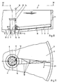
- Figure 1 is a round settling tank 1 with 2 and Pool wall 3 shown in section.
- the training is rotationally symmetrical to a vertical central axis 4.
- Die Pelvic sole 2 is slightly inclined and goes inside Area into a funnel 5, which is only partially here is indicated and ultimately the sedimented Sludge is withdrawn from the clarifier.
- Coaxial to the Central axis 4 is one that ends below the water surface Inlet pipe 6 arranged through which the sedimentation contaminated waste water according to arrow 7 in the interior of the Circular clarifier 1 is introduced.
- the new underwater clearer is at least essential Parts arranged below the water surface. It is a Clearing blade 8, which can be equipped with a rubber lip 9 can, provided.
- the clearing blade 8 extends radially Direction from an inner area approximately following the Funnel 5 radially outwards into the area of the pool wall 3.
- the clearing blade 8 with its rubber lip 9 extends parallel to the pelvic floor 2, is also easy here provided inclined.
- the clearing blade 8 is a frame 10 assigned, which, as shown in Figure 2, expediently is composed of several struts.
- the frame 10 has approximately sector-like shape and in this case, i.e. H. with an external drive, according to the sector-like Distribution of the base of the pelvic floor 2 arranged. With the Frame 10, a ring gear 11 is firmly connected.
- both the clearing blade 8 and the frame 10 and the Gear ring 11 in a compact design with a low height are provided below the water surface to pass through their Orbital movement the flow conditions and especially that Sedimentation in the circular clarifier 1 not to be disturbed.
- a drive pinion 12 which on sits lower end of a shaft 13 which is supported in bearings 14 is.
- the bearings 14 are attached to the inside of the pool wall 3.
- a motor 15 which is only here is indicated schematically and in particular as a geared motor can be trained.
- additional bearings 16 are provided at intervals, the guide rollers 17 for the ring gear 11 or one connected to it Have profile 18.
- a wheel flange 19 mounted on the stationary expediently support at least two flanged wheels 20 which are mounted on the outside of the frame 10.
- the dozer blade 8 is very slow is continuously driven to minimize the stirring effect hold and on the other hand a transport of the sedimented Sludge radially from the outside in, ultimately in the Funnel 5 into it.
- a transport of the sedimented Sludge radially from the outside in, ultimately in the Funnel 5 into it is possible, as in Figure 2 in dashed lines Lines indicated, the clearing blade 8 in several partial clearing blades 8 ', 8' 'etc. to divide these partial clearing blades 8', Arrange 8 '' etc. at an angle to the direction of rotation according to arrow 21 can.
- the arrangement is expediently such that the neighboring parting blades 8 ', 8' 'etc. in a radial direction Overlap direction.
- the frame 10 is also here sector-like design and arranged accordingly (Figure 5).
- ring gear 11 is not part of the frame 10 here.
- the ring gear 11 is here stationary on the stationary profile 18 provided and screwed to the pelvic floor 2, for example.
- the frame 10 has a vertical support 22 which is thin Struts 23 can be braced and held. On the vertical beam 22 and thus on the frame 10 are now the bearings 14 for Shaft 13, at the upper end of which the motor 15 is also indicated is.
- FIG. 7 schematically illustrates an embodiment, in which the frame 10 at least partially with suction bags 26 is occupied, which faces the surface of the pelvic sole 2 on Frame 10 are arranged.
- the arrangement is appropriate hit that the entire surface of the pelvic floor 2 is coated.
- Via a pump 27 and a pressure line 28 the extracted sediment is fixed via a central axis 4 arranged discharge pipe 29 discharged.
- the derivation through Vacuum according to the lifting principle can be used here.
- the rotating drive of the frame 10 can alternatively on the two Types are brought about using the exemplary embodiments of Figures 1 to 3 on the one hand and 4 to 6 on the other hand already have been described.
- the particular advantage of this embodiment 7 is that the funnel 5 in Elimination can occur and the pelvic sole 2 continuously can just be trained.
- FIG. 8 to 10 shows the underwater clearer with internal drive, i.e. close to the central axis 4.
- the embodiment shows similarities to that Embodiment according to Figures 1 to 3, but in which Drive is arranged radially outside.
- the inlet pipe 6 extends the fixed wheel flange 19.
- the profile 18 is connected, which on the inside Sprocket 11 carries and otherwise on flange wheels 20 on the Wheel flange 19 is supported.
- Bearings 16 hold guide rollers 17, which are arranged inside or outside the profile 18 can.
- the shaft 13 is rotatable in bearings 14 but stationary held, which in turn may be attached to the inlet pipe 6.
- the motor 15 At the upper end of the shaft 13 is the motor 15, while the lower end is provided with the drive pinion 12, which in FIG.
- the frame 10 extends radially from the inside out and it has one compared to the circular clarifier 1, arranged in reverse, sector-like Shape, d. H. it is wide on the inside and runs radially sharp outside.
- FIG. 11 The embodiment of Figures 11 to 13 also shows one internal drive, but with the motor 15 rotating is provided.
- This embodiment shows similarities with the embodiment according to Figures 4 to 6.
- the bearing 14 for the Wave 13 carries.
- the motor 15 At the upper end of the shaft 13 is the motor 15 and at the lower end of the drive pinion 12 indicated.
- Profile 18 is fixed here, either on the inlet pipe 6 with the help of several consoles 30 (FIG. 13) or directly on the pelvic sole 2, if this is horizontal, for example is continuous, as shown in Figure 7.
- the ring gear 11 Inside on Profile 18, the ring gear 11 is fixed, with which the Drive pinion 12 combs.
- the flange 19 which is attached to the frame 10 Flanged wheels 20 are assigned.
- the frame 10 is as stiffened, flat frame and vice versa arranged sector-like relative to the round settling tank 1, like this also shows the embodiment of Figures 8 to 10. Also a diameter-like, symmetrical double arrangement with two clearing arms is possible.
Landscapes
- Chemical & Material Sciences (AREA)
- Chemical Kinetics & Catalysis (AREA)
- Treatment Of Sludge (AREA)
- Catching Or Destruction (AREA)
- Crushing And Pulverization Processes (AREA)
- Cleaning In General (AREA)
- Underground Or Underwater Handling Of Building Materials (AREA)
Claims (3)
- Racleur immergé pour bassins circulaires de décantation (1) comportant une lame de raclage (8) s'étendant à peu près radialement, passant le long de la sole (2) du bassin circulaire de décantation (1), et qui est entraínée en rotation, dont le dispositif d'entraínement agit radialement vers l'extérieur ou radialement vers l'intérieur sur la lame de raclage (8), par l'intermédiaire d'une couronne dentée (11) prévue sous l'eau et qui n'est destinée qu'au mouvement de rotation de la lame de raclage (8), la lame de raclage (8) et un cadre (10) associé à celle-ci, qui vu de dessus forme un secteur, et qui s'étend sensiblement dans un plan horizontal ou incliné parallèlement à la sole (2) du bassin, formant une unité de construction disposée sous l'eau, un boudin (19) fixe étant prévu radialement à l'extérieur ou à l'intérieur dans la région de la sole (2) du bassin, contre lequel et sur lequel prend appui le cadre (10) avec la lame de raclage (8).
- Racleur immergé selon la revendication 1, caractérisé en ce que la couronne dentée (11) est montée sur le cadre (10) de la lame de raclage (8) de manière à tourner avec celui-ci, et un ce qu'un moteur d'entraínement (15) avec pignon d'entraínement (12) est prévu stationnaire dans la région de la paroi (3) du bassin ou dans la région centrale du bassin circulaire de décantation (1).
- Racleur immergé selon la revendication 1, caractérisé en ce que la couronne dentée (11) est prévue stationnaire sur le bassin circulaire de décantation (1), et en ce qu'un moteur d'entraínement (15) avec pignon d'entraínement est monté sur le cadre (10) de manière à tourner avec celui-ci.
Applications Claiming Priority (3)
| Application Number | Priority Date | Filing Date | Title |
|---|---|---|---|
| DE4222559 | 1992-07-09 | ||
| DE4222559A DE4222559C2 (de) | 1992-07-09 | 1992-07-09 | Unterwasserräumer für Rundklärbecken |
| PCT/EP1993/001795 WO1994001191A1 (fr) | 1992-07-09 | 1993-07-09 | Racleur immerge pour bassins ronds de decantation |
Publications (2)
| Publication Number | Publication Date |
|---|---|
| EP0603379A1 EP0603379A1 (fr) | 1994-06-29 |
| EP0603379B1 true EP0603379B1 (fr) | 1999-04-28 |
Family
ID=6462841
Family Applications (1)
| Application Number | Title | Priority Date | Filing Date |
|---|---|---|---|
| EP93915859A Expired - Lifetime EP0603379B1 (fr) | 1992-07-09 | 1993-07-09 | Racleur immerge pour bassins ronds de decantation |
Country Status (7)
| Country | Link |
|---|---|
| US (1) | US5422006A (fr) |
| EP (1) | EP0603379B1 (fr) |
| JP (1) | JP3296559B2 (fr) |
| AT (1) | ATE179343T1 (fr) |
| DE (2) | DE4222559C2 (fr) |
| PL (1) | PL302574A1 (fr) |
| WO (1) | WO1994001191A1 (fr) |
Cited By (1)
| Publication number | Priority date | Publication date | Assignee | Title |
|---|---|---|---|---|
| CN102179072A (zh) * | 2011-05-06 | 2011-09-14 | 上海市松江自来水公司 | 一种用于沉淀池排泥的刮泥装置 |
Families Citing this family (16)
| Publication number | Priority date | Publication date | Assignee | Title |
|---|---|---|---|---|
| DE4412647C2 (de) * | 1994-04-13 | 1996-11-28 | Hans Georg Huber | Räumer für Rundklärbecken |
| US5966154A (en) * | 1997-10-17 | 1999-10-12 | Eastman Kodak Company | Graphic arts printing plate production by a continuous jet drop printing with asymmetric heating drop deflection |
| RU2164437C2 (ru) * | 2000-01-18 | 2001-03-27 | Чернявская Галина Викторовна | Радиальный отстойник |
| US6536606B2 (en) | 2001-07-24 | 2003-03-25 | United States Filter Corporation | Sludge collector with entrapment plate |
| NZ513379A (en) * | 2001-08-07 | 2004-03-26 | Power Glides Screens Ltd | Suspension screen raking system (NO.2) |
| US7637379B2 (en) * | 2006-12-07 | 2009-12-29 | Council Of Scientific & Industrial Research | Circular secondary clarifier for wastewater treatment and an improved solids-liquid separation process thereof |
| DE102008056295A1 (de) * | 2008-11-07 | 2010-05-12 | Hamburger Stadtentwässerung Anstalt des öffentlichen Rechts | Räumer für Rundabsetzbecken |
| ES2391018B1 (es) * | 2010-03-01 | 2013-10-17 | Serveis Barmatec, S.L | Dispositivo para mover un bastidor de recogida de solidos o espumas de un tanque de sedimentacion y tanque de sedimentacion que incluye dicho dispositivo |
| US20120012540A1 (en) * | 2010-07-16 | 2012-01-19 | Highmark Renewables Research , L.P. | Grit removal system |
| SE537514C2 (sv) * | 2011-08-23 | 2015-05-26 | Nordic Water Prod Ab | System och sätt för avlägsnande av slam i en cirkulär sedimenteringstank |
| CN102974135B (zh) * | 2012-12-24 | 2015-09-02 | 净化控股集团有限公司 | 一种沉淀池刮泥机的牵引装置 |
| RU2569097C2 (ru) * | 2014-03-28 | 2015-11-20 | Государственное Унитарное Предприятие "Водоканал Санкт-Петербурга" | Способ контроля над движением активного водила илоскреба радиального отстойника |
| CN105920885A (zh) * | 2016-06-06 | 2016-09-07 | 江苏腾丰环保科技有限公司 | 一种周边传动刮泥机 |
| ES2649049B1 (es) * | 2016-07-07 | 2018-09-27 | Parcitank, S.A. | Dispositivo barredor de depósitos |
| US20240279093A1 (en) * | 2021-08-04 | 2024-08-22 | Evoqua Water Technologies Llc | Radial Inflow Diffuser for Clarifier |
| CN114809252A (zh) * | 2022-03-26 | 2022-07-29 | 北京金河水务建设集团有限公司 | 一种具有自动清污功能的硅砂蓄水净水池及其施工工艺 |
Family Cites Families (16)
| Publication number | Priority date | Publication date | Assignee | Title |
|---|---|---|---|---|
| AT43241B (de) * | 1908-03-03 | 1910-07-25 | Maschb Ges Martini & Hueneke M | Verfahren und Einrichtung zur Reinigung von Behältern für feuergefährliche Flüssigkeiten und dergl. |
| US1972584A (en) * | 1932-09-06 | 1934-09-04 | Elton E Easterday | Settling apparatus |
| GB502469A (en) * | 1938-10-10 | 1939-03-17 | Hellmut Geiger | Driving mechanism for rotary sludge removers in circular settling tanks |
| US2506927A (en) * | 1946-02-16 | 1950-05-09 | Process Engineers Inc | Clarification |
| BE525460A (fr) * | 1953-11-16 | |||
| FR1187240A (fr) * | 1957-11-21 | 1959-09-08 | Procédé et dispositif d'évacuation des boues d'un décanteur | |
| US3465886A (en) * | 1967-06-14 | 1969-09-09 | Laval Turbine | Collection and input apparatus for a bath undergoing gravitational classification |
| DE2160194A1 (de) * | 1971-12-04 | 1973-06-14 | Voith Gmbh J M | Rundklaerbecken zum klaeren von abwasser |
| US4005019A (en) | 1974-09-27 | 1977-01-25 | L.S. Love & Associates Limited | Gravitational separator |
| DE2551907B2 (de) * | 1975-11-19 | 1979-06-07 | Fried. Krupp Gmbh, 4300 Essen | Flockungsreaktor |
| JPS5737368A (en) * | 1980-08-19 | 1982-03-01 | Konishiroku Photo Ind Co Ltd | Copying device |
| DE8109945U1 (de) * | 1981-04-02 | 1981-10-22 | Gebr. Bellmer Kg Maschinenfabrik, 7532 Niefern | Schlammeindicker oder rundraeumer fuer klaeranlagen |
| DE3135215A1 (de) * | 1981-09-05 | 1983-11-10 | Menzel Gmbh & Co, 7000 Stuttgart | Raeumer |
| US4594156A (en) * | 1985-07-05 | 1986-06-10 | Lakeside Equipment Corporation | Motorized surface scum skimmer for waste water treatment apparatus |
| DE3540606A1 (de) * | 1985-11-15 | 1987-05-21 | Krupp Koppers Gmbh | Mit lamellenpaketen versehenes rundes klaerbecken |
| US4859346A (en) * | 1988-06-17 | 1989-08-22 | Bakers Hughes Inc. | Ground mounted traction drive and method for sedimentation device |
-
1992
- 1992-07-09 DE DE4222559A patent/DE4222559C2/de not_active Expired - Fee Related
-
1993
- 1993-07-09 WO PCT/EP1993/001795 patent/WO1994001191A1/fr not_active Ceased
- 1993-07-09 PL PL93302574A patent/PL302574A1/xx unknown
- 1993-07-09 AT AT93915859T patent/ATE179343T1/de not_active IP Right Cessation
- 1993-07-09 US US08/190,141 patent/US5422006A/en not_active Expired - Fee Related
- 1993-07-09 DE DE59309545T patent/DE59309545D1/de not_active Expired - Fee Related
- 1993-07-09 JP JP50297494A patent/JP3296559B2/ja not_active Expired - Fee Related
- 1993-07-09 EP EP93915859A patent/EP0603379B1/fr not_active Expired - Lifetime
Cited By (2)
| Publication number | Priority date | Publication date | Assignee | Title |
|---|---|---|---|---|
| CN102179072A (zh) * | 2011-05-06 | 2011-09-14 | 上海市松江自来水公司 | 一种用于沉淀池排泥的刮泥装置 |
| CN102179072B (zh) * | 2011-05-06 | 2012-11-21 | 上海市松江自来水公司 | 一种用于沉淀池排泥的刮泥装置 |
Also Published As
| Publication number | Publication date |
|---|---|
| WO1994001191A1 (fr) | 1994-01-20 |
| PL302574A1 (en) | 1994-07-25 |
| JP3296559B2 (ja) | 2002-07-02 |
| DE4222559C2 (de) | 1994-07-28 |
| DE4222559A1 (de) | 1994-01-13 |
| DE59309545D1 (de) | 1999-06-02 |
| JPH06510482A (ja) | 1994-11-24 |
| US5422006A (en) | 1995-06-06 |
| EP0603379A1 (fr) | 1994-06-29 |
| ATE179343T1 (de) | 1999-05-15 |
Similar Documents
| Publication | Publication Date | Title |
|---|---|---|
| EP0603379B1 (fr) | Racleur immerge pour bassins ronds de decantation | |
| DE2501547B2 (de) | Zylindersieb zur Trennung von flüssigen Bestandteilen von festen Bestandteilen | |
| DE1811507A1 (de) | Verfahren und Vorrichtung zum Abscheiden suspendierter fester Stoffe aus Fluessigkeiten | |
| EP0556431B1 (fr) | Bassin de clarification | |
| DE19621914C1 (de) | Fermenter | |
| DE19627161B4 (de) | Verfahren zum Abräumen von Schwimmstoffen und Räumvorrichtung | |
| DE4412647C2 (de) | Räumer für Rundklärbecken | |
| EP0714686B1 (fr) | Bassin de décantation pour stations d'épuration | |
| DE2551907A1 (de) | Flockungsreaktor | |
| DE4322930C1 (de) | Unterwasserräumer für Rundklärbecken | |
| DE10056918A1 (de) | Rundbeckenräumer | |
| DE2740645A1 (de) | Rundraeumer zur abwasserklaerung | |
| DE2160194A1 (de) | Rundklaerbecken zum klaeren von abwasser | |
| DE961249C (de) | Kontinuierlich arbeitendes Klaerbecken fuer griessige und nichtgriessige Stoffe enthaltende Abwaesserfluessigkeiten | |
| DE711914C (de) | Vorrichtung zum Ausraeumen runder Absetzbehaelter | |
| DE2065056A1 (en) | Activated sludge effluent pruficn plant - for use with varying effluent flow | |
| DE395767C (de) | Klaervorrichtung | |
| AT262326B (de) | Verfahren und Vorrichtung für das Entfernen der Feststoffe bei der mechanischen Klärung von Suspensionen in einem Absetzbehälter | |
| JP2542013Y2 (ja) | 抽水設備用撹拌処理装置 | |
| DE19529364A1 (de) | Behälter mit fahrbar gelagerten Behandlungsvorrichtungen | |
| DE2310470A1 (de) | Raeumvorrichtung fuer flotationsbecken | |
| DE1584934A1 (de) | Vorrichtung zur Klaerung von Abwaessern nach dem Belebtschlammverfahren | |
| DE10049713A1 (de) | Rundbeckenräumer | |
| DE7308020U (de) | Raeumvorrichtung fuer flotationsbecken | |
| DE9306746U1 (de) | Vorrichtung für den periodischen Betrieb eienr biologischen Abwasserreinigung nach dem SBR-Prinzip |
Legal Events
| Date | Code | Title | Description |
|---|---|---|---|
| PUAI | Public reference made under article 153(3) epc to a published international application that has entered the european phase |
Free format text: ORIGINAL CODE: 0009012 |
|
| AK | Designated contracting states |
Kind code of ref document: A1 Designated state(s): AT BE CH DE DK ES FR GB GR IE IT LI LU MC NL PT SE |
|
| 17P | Request for examination filed |
Effective date: 19940621 |
|
| 17Q | First examination report despatched |
Effective date: 19951205 |
|
| GRAG | Despatch of communication of intention to grant |
Free format text: ORIGINAL CODE: EPIDOS AGRA |
|
| GRAG | Despatch of communication of intention to grant |
Free format text: ORIGINAL CODE: EPIDOS AGRA |
|
| GRAH | Despatch of communication of intention to grant a patent |
Free format text: ORIGINAL CODE: EPIDOS IGRA |
|
| GRAH | Despatch of communication of intention to grant a patent |
Free format text: ORIGINAL CODE: EPIDOS IGRA |
|
| GRAA | (expected) grant |
Free format text: ORIGINAL CODE: 0009210 |
|
| AK | Designated contracting states |
Kind code of ref document: B1 Designated state(s): AT BE CH DE DK ES FR GB GR IE IT LI LU MC NL PT SE |
|
| PG25 | Lapsed in a contracting state [announced via postgrant information from national office to epo] |
Ref country code: SE Free format text: THE PATENT HAS BEEN ANNULLED BY A DECISION OF A NATIONAL AUTHORITY Effective date: 19990428 Ref country code: NL Free format text: LAPSE BECAUSE OF FAILURE TO SUBMIT A TRANSLATION OF THE DESCRIPTION OR TO PAY THE FEE WITHIN THE PRESCRIBED TIME-LIMIT Effective date: 19990428 Ref country code: GR Free format text: LAPSE BECAUSE OF NON-PAYMENT OF DUE FEES Effective date: 19990428 Ref country code: GB Free format text: LAPSE BECAUSE OF FAILURE TO SUBMIT A TRANSLATION OF THE DESCRIPTION OR TO PAY THE FEE WITHIN THE PRESCRIBED TIME-LIMIT Effective date: 19990428 Ref country code: ES Free format text: THE PATENT HAS BEEN ANNULLED BY A DECISION OF A NATIONAL AUTHORITY Effective date: 19990428 |
|
| REF | Corresponds to: |
Ref document number: 179343 Country of ref document: AT Date of ref document: 19990515 Kind code of ref document: T |
|
| REG | Reference to a national code |
Ref country code: CH Ref legal event code: EP |
|
| ITF | It: translation for a ep patent filed | ||
| REG | Reference to a national code |
Ref country code: IE Ref legal event code: FG4D Free format text: GERMAN |
|
| REF | Corresponds to: |
Ref document number: 59309545 Country of ref document: DE Date of ref document: 19990602 |
|
| ET | Fr: translation filed | ||
| PG25 | Lapsed in a contracting state [announced via postgrant information from national office to epo] |
Ref country code: LU Free format text: LAPSE BECAUSE OF NON-PAYMENT OF DUE FEES Effective date: 19990709 Ref country code: IE Free format text: LAPSE BECAUSE OF NON-PAYMENT OF DUE FEES Effective date: 19990709 |
|
| PG25 | Lapsed in a contracting state [announced via postgrant information from national office to epo] |
Ref country code: DK Free format text: LAPSE BECAUSE OF FAILURE TO SUBMIT A TRANSLATION OF THE DESCRIPTION OR TO PAY THE FEE WITHIN THE PRESCRIBED TIME-LIMIT Effective date: 19990728 |
|
| PG25 | Lapsed in a contracting state [announced via postgrant information from national office to epo] |
Ref country code: PT Free format text: LAPSE BECAUSE OF FAILURE TO SUBMIT A TRANSLATION OF THE DESCRIPTION OR TO PAY THE FEE WITHIN THE PRESCRIBED TIME-LIMIT Effective date: 19990729 |
|
| PG25 | Lapsed in a contracting state [announced via postgrant information from national office to epo] |
Ref country code: LI Free format text: LAPSE BECAUSE OF NON-PAYMENT OF DUE FEES Effective date: 19990731 Ref country code: CH Free format text: LAPSE BECAUSE OF NON-PAYMENT OF DUE FEES Effective date: 19990731 Ref country code: BE Free format text: LAPSE BECAUSE OF NON-PAYMENT OF DUE FEES Effective date: 19990731 |
|
| GBV | Gb: ep patent (uk) treated as always having been void in accordance with gb section 77(7)/1977 [no translation filed] |
Effective date: 19990428 |
|
| BERE | Be: lapsed |
Owner name: HUBER HANS-GEORG Effective date: 19990731 |
|
| PG25 | Lapsed in a contracting state [announced via postgrant information from national office to epo] |
Ref country code: MC Free format text: LAPSE BECAUSE OF NON-PAYMENT OF DUE FEES Effective date: 20000131 |
|
| PLBE | No opposition filed within time limit |
Free format text: ORIGINAL CODE: 0009261 |
|
| STAA | Information on the status of an ep patent application or granted ep patent |
Free format text: STATUS: NO OPPOSITION FILED WITHIN TIME LIMIT |
|
| REG | Reference to a national code |
Ref country code: CH Ref legal event code: PL |
|
| 26N | No opposition filed | ||
| REG | Reference to a national code |
Ref country code: IE Ref legal event code: MM4A |
|
| PGFP | Annual fee paid to national office [announced via postgrant information from national office to epo] |
Ref country code: FR Payment date: 20000718 Year of fee payment: 8 |
|
| PGFP | Annual fee paid to national office [announced via postgrant information from national office to epo] |
Ref country code: AT Payment date: 20000721 Year of fee payment: 8 |
|
| PG25 | Lapsed in a contracting state [announced via postgrant information from national office to epo] |
Ref country code: AT Free format text: LAPSE BECAUSE OF NON-PAYMENT OF DUE FEES Effective date: 20010709 |
|
| PG25 | Lapsed in a contracting state [announced via postgrant information from national office to epo] |
Ref country code: FR Free format text: LAPSE BECAUSE OF NON-PAYMENT OF DUE FEES Effective date: 20020329 |
|
| REG | Reference to a national code |
Ref country code: FR Ref legal event code: ST |
|
| PGFP | Annual fee paid to national office [announced via postgrant information from national office to epo] |
Ref country code: DE Payment date: 20030710 Year of fee payment: 11 |
|
| PG25 | Lapsed in a contracting state [announced via postgrant information from national office to epo] |
Ref country code: DE Free format text: LAPSE BECAUSE OF NON-PAYMENT OF DUE FEES Effective date: 20050201 |
|
| PG25 | Lapsed in a contracting state [announced via postgrant information from national office to epo] |
Ref country code: IT Free format text: LAPSE BECAUSE OF NON-PAYMENT OF DUE FEES;WARNING: LAPSES OF ITALIAN PATENTS WITH EFFECTIVE DATE BEFORE 2007 MAY HAVE OCCURRED AT ANY TIME BEFORE 2007. THE CORRECT EFFECTIVE DATE MAY BE DIFFERENT FROM THE ONE RECORDED. Effective date: 20050709 |