EP0603423B1 - Dispositif pour l'implantation d'une endoprothese - Google Patents
Dispositif pour l'implantation d'une endoprothese Download PDFInfo
- Publication number
- EP0603423B1 EP0603423B1 EP92121677A EP92121677A EP0603423B1 EP 0603423 B1 EP0603423 B1 EP 0603423B1 EP 92121677 A EP92121677 A EP 92121677A EP 92121677 A EP92121677 A EP 92121677A EP 0603423 B1 EP0603423 B1 EP 0603423B1
- Authority
- EP
- European Patent Office
- Prior art keywords
- core member
- handle
- sleeve member
- endoprosthesis
- endoprothesis
- Prior art date
- Legal status (The legal status is an assumption and is not a legal conclusion. Google has not performed a legal analysis and makes no representation as to the accuracy of the status listed.)
- Expired - Lifetime
Links
- 238000002513 implantation Methods 0.000 title claims description 11
- 210000003811 finger Anatomy 0.000 claims description 23
- 210000003813 thumb Anatomy 0.000 claims description 9
- 241001465754 Metazoa Species 0.000 claims description 3
- 210000004932 little finger Anatomy 0.000 claims description 2
- 241000321728 Tritogonia verrucosa Species 0.000 claims 4
- KHOITXIGCFIULA-UHFFFAOYSA-N Alophen Chemical compound C1=CC(OC(=O)C)=CC=C1C(C=1N=CC=CC=1)C1=CC=C(OC(C)=O)C=C1 KHOITXIGCFIULA-UHFFFAOYSA-N 0.000 claims 1
- 239000007943 implant Substances 0.000 description 6
- 238000000034 method Methods 0.000 description 5
- 210000000707 wrist Anatomy 0.000 description 5
- 210000003414 extremity Anatomy 0.000 description 4
- 238000006073 displacement reaction Methods 0.000 description 2
- 210000004247 hand Anatomy 0.000 description 2
- 210000003484 anatomy Anatomy 0.000 description 1
- 238000013459 approach Methods 0.000 description 1
- 210000004204 blood vessel Anatomy 0.000 description 1
- 238000013461 design Methods 0.000 description 1
- 210000000245 forearm Anatomy 0.000 description 1
- 238000002347 injection Methods 0.000 description 1
- 239000007924 injection Substances 0.000 description 1
- 238000004519 manufacturing process Methods 0.000 description 1
- 238000012544 monitoring process Methods 0.000 description 1
- 210000003205 muscle Anatomy 0.000 description 1
- 230000002040 relaxant effect Effects 0.000 description 1
- 230000000284 resting effect Effects 0.000 description 1
- 238000000926 separation method Methods 0.000 description 1
- 230000003068 static effect Effects 0.000 description 1
- 210000003437 trachea Anatomy 0.000 description 1
- 238000013519 translation Methods 0.000 description 1
- 210000001260 vocal cord Anatomy 0.000 description 1
Images

Classifications
-
- A—HUMAN NECESSITIES
- A61—MEDICAL OR VETERINARY SCIENCE; HYGIENE
- A61F—FILTERS IMPLANTABLE INTO BLOOD VESSELS; PROSTHESES; DEVICES PROVIDING PATENCY TO, OR PREVENTING COLLAPSING OF, TUBULAR STRUCTURES OF THE BODY, e.g. STENTS; ORTHOPAEDIC, NURSING OR CONTRACEPTIVE DEVICES; FOMENTATION; TREATMENT OR PROTECTION OF EYES OR EARS; BANDAGES, DRESSINGS OR ABSORBENT PADS; FIRST-AID KITS
- A61F2/00—Filters implantable into blood vessels; Prostheses, i.e. artificial substitutes or replacements for parts of the body; Appliances for connecting them with the body; Devices providing patency to, or preventing collapsing of, tubular structures of the body, e.g. stents
- A61F2/95—Instruments specially adapted for placement or removal of stents or stent-grafts
-
- A—HUMAN NECESSITIES
- A61—MEDICAL OR VETERINARY SCIENCE; HYGIENE
- A61F—FILTERS IMPLANTABLE INTO BLOOD VESSELS; PROSTHESES; DEVICES PROVIDING PATENCY TO, OR PREVENTING COLLAPSING OF, TUBULAR STRUCTURES OF THE BODY, e.g. STENTS; ORTHOPAEDIC, NURSING OR CONTRACEPTIVE DEVICES; FOMENTATION; TREATMENT OR PROTECTION OF EYES OR EARS; BANDAGES, DRESSINGS OR ABSORBENT PADS; FIRST-AID KITS
- A61F2/00—Filters implantable into blood vessels; Prostheses, i.e. artificial substitutes or replacements for parts of the body; Appliances for connecting them with the body; Devices providing patency to, or preventing collapsing of, tubular structures of the body, e.g. stents
- A61F2/95—Instruments specially adapted for placement or removal of stents or stent-grafts
- A61F2/9517—Instruments specially adapted for placement or removal of stents or stent-grafts handle assemblies therefor
Definitions
- the present invention relates to a device for implanting an endoprosthesis into a channel-shaped vessel of the human or animal body as defined in claims 1 to 6.
- Implanted endoprostheses are generally used for narrowing the lumen, for example for narrowing blood vessels.
- These endoprostheses also called stents, are often wire mesh tubes that are constructed from such elastic filaments that the wire mesh tube is brought in a radially compressed state by means of an implantation device to the location of the vessel to be treated, after which the The implantation device releases the endoprosthesis so that it can expand, attach to the walls of the vessel and expand the constriction.
- the wire mesh tube or a correspondingly constructed endoprosthesis is clamped in the radially compressed state in an outer sleeve member.
- a core member In the interior of the sleeve member is a core member provided with a shoulder and designed as a stationary pusher.
- the core member is axially displaceable relative to the outer sleeve and can rest on the endoprosthesis with its shoulder.
- the sleeve member is moved relative to the core member.
- the core member is held stationary for this relative movement and the sleeve member is withdrawn.
- the endoprosthesis at the distal end of the sleeve member will exit properly and the endoprosthesis will be released, but the endoprosthesis will be advanced in the vessel during this procedure and the vessel is injured as a result. Without the physician being able to visually check this in real-time images, the free ends of the endoprosthesis drill into the vessel wall. At the same time, the elements of the endoprosthesis that are not designed for this load, for example, the elastic filaments mentioned, permanently deform and render the endoprosthesis ineffective.
- Implantation devices have already been proposed which allow the endoprosthesis to be folded back into the outer sleeve member.
- the bent and thus ineffective endoprosthesis may have to remain in the vessel.
- the location of the ineffective endoprosthesis can no longer be changed. At most, as long as it is only partially unfolded, it can be pulled towards the operating side within narrow limits. In the worst case, an endoprosthesis that has become unusable must remain exactly at the location in the vessel at which an intact endoprosthesis was indicated, that is, at the location where the vessel is pathologically changed.
- the end on the operator side is designed such that the relative movement between the core member and the outer sleeve member can be carried out easily and safely in a scissor movement.
- the known devices have the disadvantage that the actuating handles are designed in such a way that both types of movement, the correct type of movement with a stationary core member and the wrong one Movement type with a stationary sleeve member, completely equivalent are allowed side by side.
- the known handle arrangements result in no preferred handling.
- the scissor movement suggested by the known handles includes the one correct movement, but also a number of incorrect forms of movement.
- the handle arrangement of the known devices can be associated by the individual operators with the actuation arrangement of a conventional injection syringe.
- the plunger is normally advanced towards the outer cylinder. Exactly this movement is the wrong movement here.
- US-A-4 665 918 discloses an apparatus for implanting an endoprosthesis which has a core member on which the endoprosthesis is to be placed in a compressed state.
- This core member is arranged to be longitudinally displaceable in a first sleeve member, which serves to hold the endoprosthesis in the compressed state. If the first sleeve member is pulled back relative to the first core member, the endoprosthesis is released.
- the first sleeve member is in turn arranged longitudinally displaceably in a second sleeve member.
- the first sleeve member and the core member are then pushed together a short distance out of the second sleeve member, and finally the core member is pushed out of the first sleeve member to release the endoprosthesis.
- a large number of uncomfortable handles are required, which can only be gripped with fingers, and there is no handle by means of which the device is reliably pushed into a starting position for releasing the endoprosthesis and is held there immovably at the relevant point can.
- the invention seeks to remedy this.
- the invention as characterized in the claims, achieves the object of providing an apparatus for implanting an endoprosthesis into a channel-shaped vessel of the human or animal body which is simple to manufacture and whose placement at the starting position before the endoprosthesis is released is made easier , which places low demands on the dexterity of the operator and in which the correct operation of the device makes it easier, but the wrong operation is more difficult.
- the invention ensures that the implant device can be placed in the correct starting position with the necessary reliability and safety before the endoprosthesis is released.
- the outer sleeve member is secured against the core member by the locking device. It is no longer necessary to manipulate the outer sleeve member for placing the implantation device, but rather the inner core member, which protrudes further at the proximal end of the device, can be used to manipulate the entire device.
- a protruding pistol grip-shaped handle designed for gripping with the thumb and the first limb of the index finger is now arranged on this inner core member.
- the protruding pistol grip shape which can be gripped in the specified form, controls both the control and the feed of the implantation device by the operator's wrist. With the forces that arise here, this is a safe, reliable and precise control that requires less dexterity from the doctor.
- the invention takes a completely different approach to operating the device. Either the finger is moved towards the wrist when the handle on the outer sleeve is within reach of the pistol grip, or the second hand is used to move the scissors. In the first case, it is a gripping movement and thus the simplest conceivable operating movement at all. It requires the least amount of skill, dexterity and attention.
- the handles of the outer sleeve and the inner core are designed very differently according to the invention, each for a different form of gripping. Incorrect operation of the device is made significantly more difficult, the handles would have to be gripped in a form for which they are not designed. However, this means that the choice between correct and incorrect operation is not left to the mind of the doctor alone. In the arrangement according to the invention, before the incorrect operation can actually be carried out, the incorrect selection also clear obstacles in the manipulation to be overcome. An involuntary incorrect operation is therefore practically impossible.
- the pistol grip provided in the combination of features of the invention is known from many areas of life and is used in the invention precisely for the type of operation for which it is also known from the other areas.
- the combination of features of the invention therefore also suggests the form of operation to the impartial observer; in particular, the design according to the invention cannot produce false associations which can result in incorrect operation.
- the device can be operated more easily with two hands.
- One hand only has the task of bringing about the relative movement between the sleeve member and the core member, the other hand is only available for holding the device stationary without additional tasks.
- the entire span of the hand can be used to bring about the relative movement, and therefore a particularly long endoprosthesis can be released without direct translation.
- the pistol grip can not only be gripped particularly effectively by the thumb and the first limb of the index finger, but in this case it can be enclosed by the whole hand.
- a particularly sensitive positioning of the device in the starting position for releasing the endoprosthesis and when releasing a particularly reliable holding in a stationary position is possible if the pistol-shaped handle on the core member is designed to be encased with middle, ring and little fingers.
- the actuating handle of the sleeve member has two diametrically opposite projections, the further handle of the core member diametrically opposite the pistol grip handle, and the two projections of the sleeve member lie in a plane that coincides with the plane determined by the pistol grip handle and the further handle , enables the operator to have an attitude that is very accommodating to the human anatomy. There are no sharp bends on the wrists and the operator's forearms are at an angle of approximately 90 degrees to each other when operating the device. Because extreme positions of the operator's limbs are avoided a high level of safety and reliability in operation is guaranteed.
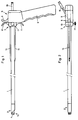
- the implantation device is basically composed of two parts, an outer sleeve member 1 and an inner core member 4. These two links can be moved relative to one another.
- the distal end 2 of the sleeve member 1 is diverging and further bevelled. In this distal end 2, the endoprosthesis is cut to a desired length and inserted and held in an elastically compressed state.
- At the proximal end 3 of the sleeve member 1 there are two projections 10, 11 and it can be seen that a retraction movement of the sleeve member 1 relative to the core member 4, which will be discussed below, exclusively by fingers encompassing these projections 10, 11, e.g. Index finger and the middle finger of the human hand is enabled.
- a shoulder 7 is formed at the distal end 5 of the core member 4.
- the core member 4 is designed as a stationary plunger, which can act on an end face of an endoprosthesis.
- the core member 4 has a pistol grip-shaped handle 8 at the proximal end 6. This diametrically opposite is another handle 9 acting as an abutment. It can be seen that the pistol grip Handle 8, the further handle 9, the projection 10 and the projection 11 all run in the same plane.
- the core member 4 which is hollow cylindrical due to the interior, can also accommodate other medical instruments in the interior.
- an endoscope can be arranged in the core member 4. The placement of the endoprosthesis can thus take place under sight. Again, the connection would run through the connection 16 from the outside.
- the sleeve member 1 also has a locking screw 17 at the proximal end 3, by means of which the sleeve member 1 can be locked on the core member 4.
- the handling of the device is as follows.
- the sleeve member 1 is advanced to the left on the core member 4 in the figures, so that the shoulder 7 of the core member 4 comes to lie within the sleeve member 1.
- the sleeve member 1 is locked on the core member 4 by tightening the locking screw 17.
- the endoprosthesis is then inserted at the distal end 2 into the sleeve member 1 in the elastically compressed state, so that it lies opposite the shoulder 7 of the core member 4 at one end.
- a Touch is not absolutely necessary since the endoprosthesis rests against the inner wall of the sleeve member 1 due to its elastic pretensioning force and is thus held against unintentional displacement.
- the doctor grips the pistol grip-shaped handle 8 at least with the thumb and the first limb of the index finger.
- the implant device with the endoprosthesis is then inserted into the Vessel inserted until the endoprosthesis is positioned exactly at the desired location in the vessel.
- the procedures for monitoring and checking the location of such endoprostheses are also generally known. It is now obvious that the handle, which is shaped like a pistol grip, enables extremely safe manipulation of the device, and rotation if necessary.
- the locking screw 17 is first loosened by the other hand and then by applying two fingers of the other hand to the projections 10 and 11 and by applying the thumb of this hand to the abutment-shaped projection 9, the sleeve member 1 slowly towards the pistol grip handle 8 are withdrawn. Since the handle 8 is basically still enclosed by the fist, the force acting on the projections 10, 11 and thus on the sleeve member 1 is smaller than the force acting on the core member 4, which must now be held immovably, so that an unwanted displacement of the Endoprosthesis is not possible during this manipulation.
- the endoprosthesis By resting on the shoulder 7 of the core member 4, the endoprosthesis will emerge from the interior of the sleeve member 1 by pulling back the sleeve member 1 and can now expand in a relaxing manner, rest against the inner wall of the vessel to be treated and fulfill its expanding function there.
- the implantation in the sense of this invention also includes a temporary placement of an endoprosthesis in a vessel.
Landscapes
- Health & Medical Sciences (AREA)
- Engineering & Computer Science (AREA)
- Biomedical Technology (AREA)
- Life Sciences & Earth Sciences (AREA)
- General Health & Medical Sciences (AREA)
- Transplantation (AREA)
- Heart & Thoracic Surgery (AREA)
- Vascular Medicine (AREA)
- Cardiology (AREA)
- Animal Behavior & Ethology (AREA)
- Oral & Maxillofacial Surgery (AREA)
- Public Health (AREA)
- Veterinary Medicine (AREA)
- Prostheses (AREA)
- Surgical Instruments (AREA)
- Media Introduction/Drainage Providing Device (AREA)
- Massaging Devices (AREA)
Claims (6)
- Instrument pour l'implantation d'une endoprothèse dans une cavité en forme de canal du corps humain ou animal, avec une coque en forme de douille tubulaire allongée (1) comprenant une extrémité distale (2) et une extrémité proximale (3), l'extrémité distale étant agencée pour recevoir une endoprothèse destinée à y être insérée sous une forme radialement comprimée, et avec un organe central formant un poussoir stationnaire (4) allongé, disposé dans la coque extérieure (1) coaxialement à celle-ci et déplaçable par rapport à elle, ce poussoir présentant une extrémité distale (5) et une extrémité proximale (6), la région de l'extrémité distale (5) comportant un épaulement (7) destiné à s'adosser à une endoprothèse qui y est insérée, de façon à ce qu'une endoprothèse introduite dans la coque (1) puisse en être expulsée par un mouvement relatif de la coque (1) par rapport à l'organe central (4), l'endoprothèse se dilatant ainsi d'elle-même et s'appliquant contre la paroi de la cavité, la coque (1) et l'organe central (4) possédant chacun à leur extrémité proximale une poignée de manoeuvre (3, respectivement 6), l'instrument possédant un dispositif (17) pour arrêter la coque extérieure par rapport à l'organe central dont la poignée de manoeuvre ressemble à une poignée protubérante de revolver (8) et est prévue pour être saisie par le pouce et la première phalange de l'index d'une main humaine afin de tenir l'instrument lors du placement de l'endoprothèse dans la cavité, la poignée de manoeuvre de la coque (1) comportant deux saillies (10, 11) diamétralement opposées qui protubèrent pour former appui pour un doigt qui y repose d'un côté sans entourer la poignée, une autre poignée (9) de l'organe central (4) étant diamétralement opposée à la poignée (8) ressemblant à une poignée de revolver, les deux saillies (10, 11) de la coque (1) étant situées dans un plan qui coïncide avec celui déterminé par l'autre poignée (9) et la poignée (8) ressemblant à une poignée de revolver.
- Instrument selon la revendication 1, caractérisé en ce que l'autre poignée (9) est agencée pour former un appui pour un doigt agissant sur un côté et n'entourant pas la poignée.
- Instrument selon la revendication 1 ou 2, caractérisé en ce que la poignée (8) ressemblant à une poignée de revolver sur l'organe central (4) est conformée pour être entourée par le majeur, l'annulaire et l'auriculaire d'une main humaine.
- Instrument selon une des revendications 1 à 3, caractérisé en ce que l'organe central (4) comporte à son extrémité proximale au moins une tige de guidage (12, 13) dirigée vers son extrémité distale qui pénètre dans un tube (14, 15) fixé à demeure sur la coque (1) et y est guidée, afin d'éviter une rotation relative de la coque (1) par rapport à l'organe central (4).
- Instrument selon une des revendications 1 à 4, caractérisé en ce que l'organe central (4) et la coque (1) sont réalisés en un matériau rigide.
- Instrument selon une des revendications 1 à 5, caractérisé en ce que l'organe central (4) forme un cylindre creux pour contenir d'autres instruments médicaux.
Priority Applications (7)
| Application Number | Priority Date | Filing Date | Title |
|---|---|---|---|
| DE59208901T DE59208901D1 (de) | 1992-12-20 | 1992-12-20 | Gerät zum Implantieren einer Endoprothese |
| ES92121677T ES2108075T3 (es) | 1992-12-20 | 1992-12-20 | Aparato para la implantacion de una endoprotesis. |
| AT92121677T ATE157857T1 (de) | 1992-12-20 | 1992-12-20 | Gerät zum implantieren einer endoprothese |
| EP92121677A EP0603423B1 (fr) | 1992-12-20 | 1992-12-20 | Dispositif pour l'implantation d'une endoprothese |
| CA2103389A CA2103389C (fr) | 1992-12-20 | 1993-11-18 | Dispositif d'implantation d'endoprotheses |
| AU52158/93A AU669581B2 (en) | 1992-12-20 | 1993-12-03 | Device for implanting an endoprosthesis |
| JP5320447A JP2648283B2 (ja) | 1992-12-20 | 1993-12-20 | 内蔵式人工臓器を埋め込むための装置 |
Applications Claiming Priority (1)
| Application Number | Priority Date | Filing Date | Title |
|---|---|---|---|
| EP92121677A EP0603423B1 (fr) | 1992-12-20 | 1992-12-20 | Dispositif pour l'implantation d'une endoprothese |
Publications (2)
| Publication Number | Publication Date |
|---|---|
| EP0603423A1 EP0603423A1 (fr) | 1994-06-29 |
| EP0603423B1 true EP0603423B1 (fr) | 1997-09-10 |
Family
ID=8210315
Family Applications (1)
| Application Number | Title | Priority Date | Filing Date |
|---|---|---|---|
| EP92121677A Expired - Lifetime EP0603423B1 (fr) | 1992-12-20 | 1992-12-20 | Dispositif pour l'implantation d'une endoprothese |
Country Status (7)
| Country | Link |
|---|---|
| EP (1) | EP0603423B1 (fr) |
| JP (1) | JP2648283B2 (fr) |
| AT (1) | ATE157857T1 (fr) |
| AU (1) | AU669581B2 (fr) |
| CA (1) | CA2103389C (fr) |
| DE (1) | DE59208901D1 (fr) |
| ES (1) | ES2108075T3 (fr) |
Cited By (1)
| Publication number | Priority date | Publication date | Assignee | Title |
|---|---|---|---|---|
| US11020255B2 (en) | 2010-06-24 | 2021-06-01 | CARDINAL HEALTH SWITZERLAND 515 GmbH | Apparatus for and method of pulling a tensile member from a medical device |
Families Citing this family (2)
| Publication number | Priority date | Publication date | Assignee | Title |
|---|---|---|---|---|
| DE4419792C1 (de) * | 1994-06-06 | 1996-02-01 | Alfons Prof Dr Med Hofstetter | Endoskop |
| FR2740024B1 (fr) * | 1995-10-23 | 1998-01-02 | Berberian Jean Pierre | Protheses de l'arbre urinaire avec leurs applicateurs |
Family Cites Families (4)
| Publication number | Priority date | Publication date | Assignee | Title |
|---|---|---|---|---|
| US4557255A (en) * | 1983-08-22 | 1985-12-10 | Goodman Tobias M | Ureteroscope |
| US4665918A (en) * | 1986-01-06 | 1987-05-19 | Garza Gilbert A | Prosthesis system and method |
| US5160341A (en) * | 1990-11-08 | 1992-11-03 | Advanced Surgical Intervention, Inc. | Resorbable urethral stent and apparatus for its insertion |
| SE503249C2 (sv) * | 1991-06-14 | 1996-04-29 | Ams Medinvent Sa | Anordning för transluminal implantation av en i huvudsak rörformig, radiellt expanderbar stent |
-
1992
- 1992-12-20 DE DE59208901T patent/DE59208901D1/de not_active Expired - Fee Related
- 1992-12-20 EP EP92121677A patent/EP0603423B1/fr not_active Expired - Lifetime
- 1992-12-20 ES ES92121677T patent/ES2108075T3/es not_active Expired - Lifetime
- 1992-12-20 AT AT92121677T patent/ATE157857T1/de not_active IP Right Cessation
-
1993
- 1993-11-18 CA CA2103389A patent/CA2103389C/fr not_active Expired - Fee Related
- 1993-12-03 AU AU52158/93A patent/AU669581B2/en not_active Ceased
- 1993-12-20 JP JP5320447A patent/JP2648283B2/ja not_active Expired - Lifetime
Cited By (1)
| Publication number | Priority date | Publication date | Assignee | Title |
|---|---|---|---|---|
| US11020255B2 (en) | 2010-06-24 | 2021-06-01 | CARDINAL HEALTH SWITZERLAND 515 GmbH | Apparatus for and method of pulling a tensile member from a medical device |
Also Published As
| Publication number | Publication date |
|---|---|
| DE59208901D1 (de) | 1997-10-16 |
| CA2103389C (fr) | 2002-07-16 |
| ES2108075T3 (es) | 1997-12-16 |
| CA2103389A1 (fr) | 1994-06-21 |
| AU669581B2 (en) | 1996-06-13 |
| JP2648283B2 (ja) | 1997-08-27 |
| JPH07534A (ja) | 1995-01-06 |
| AU5215893A (en) | 1994-06-30 |
| ATE157857T1 (de) | 1997-09-15 |
| EP0603423A1 (fr) | 1994-06-29 |
Similar Documents
| Publication | Publication Date | Title |
|---|---|---|
| DE2816961C2 (de) | Vorrichtung zum Anlegen einer Klammer an einen Eileiter | |
| DE3880676T2 (de) | Einspritzvorrichtung zum einpflanzen mehrerer arzneimittelkuegelchen. | |
| DE4306277C2 (de) | Operationsmarkierungswerkzeug | |
| DE60211044T2 (de) | Einbrinbare chirurgische Klammer mit einer Zufuhr-/Entnahmevorrichtung und Bedienelement | |
| DE69531878T2 (de) | Vorrichtung zum kontrollierten Einsetzen einer Intraokularlinse | |
| DE19704580C2 (de) | Chirurgischer Fadenschneider | |
| DE2851144C2 (de) | Chirurgisches Klammerinstrument | |
| EP1839604B1 (fr) | Dispositif destiné à l'exécution de recherches et opérations chirurgicales de l'utérus | |
| EP1964532B1 (fr) | Dispositif destiné à libérer un stent autoextensible dans un vaisseau corporel | |
| DE69923067T2 (de) | Stentplazierungsinstrument und Verfahren zum Beladen | |
| DE69633413T2 (de) | Schutz-Vorrichtung für eine Spitze | |
| DE2946833A1 (de) | Chirurgisches geraet | |
| DD160036A5 (de) | Chirurgisches klammerinstrument | |
| DE4420142C2 (de) | Vorrichtung zum Aufweiten einer Stenose | |
| DE10004979B4 (de) | System zum Einsetzen von Endoprothesen | |
| EP1083834B1 (fr) | Dispositif permettant de pratiquer un acces transcutane a un organe interne creux | |
| DE69026883T2 (de) | Gerät zum Anzeigen der Durchdringtiefe eines Trokars sowie Einstellungsgerät für eine Führungsröhre | |
| DE29717110U1 (de) | Vorrichtung zum Einführen eines Stents, eines Drainagerohrs o.dgl. in Hohlorgane | |
| DE10215751B4 (de) | Vorrichtung zum Implantieren von Markierungskörpern in einen Knochen | |
| DE202013012340U1 (de) | Werkzeuge zur transkutanen Implantation und Systeme | |
| EP2384708A1 (fr) | Dispositif d'introduction pour un cathéter à ballonnet | |
| EP0603423B1 (fr) | Dispositif pour l'implantation d'une endoprothese | |
| EP1952770A1 (fr) | Applicateur annulaire pour ligature de tube | |
| DE19707851C2 (de) | Nadelinstrument | |
| AT12408U1 (de) | Kanüle und kanülenvorrichtung zum implantieren eines implantats |
Legal Events
| Date | Code | Title | Description |
|---|---|---|---|
| PUAI | Public reference made under article 153(3) epc to a published international application that has entered the european phase |
Free format text: ORIGINAL CODE: 0009012 |
|
| 17P | Request for examination filed |
Effective date: 19921221 |
|
| AK | Designated contracting states |
Kind code of ref document: A1 Designated state(s): AT BE CH DE ES FR GB IE IT LI NL SE |
|
| 17Q | First examination report despatched |
Effective date: 19960221 |
|
| GRAG | Despatch of communication of intention to grant |
Free format text: ORIGINAL CODE: EPIDOS AGRA |
|
| GRAH | Despatch of communication of intention to grant a patent |
Free format text: ORIGINAL CODE: EPIDOS IGRA |
|
| GRAH | Despatch of communication of intention to grant a patent |
Free format text: ORIGINAL CODE: EPIDOS IGRA |
|
| GRAA | (expected) grant |
Free format text: ORIGINAL CODE: 0009210 |
|
| AK | Designated contracting states |
Kind code of ref document: B1 Designated state(s): AT BE CH DE ES FR GB IE IT LI NL SE |
|
| REF | Corresponds to: |
Ref document number: 157857 Country of ref document: AT Date of ref document: 19970915 Kind code of ref document: T |
|
| REG | Reference to a national code |
Ref country code: CH Ref legal event code: NV Representative=s name: E. BLUM & CO. PATENTANWAELTE Ref country code: CH Ref legal event code: EP |
|
| GBT | Gb: translation of ep patent filed (gb section 77(6)(a)/1977) |
Effective date: 19970912 |
|
| REF | Corresponds to: |
Ref document number: 59208901 Country of ref document: DE Date of ref document: 19971016 |
|
| ET | Fr: translation filed | ||
| ITF | It: translation for a ep patent filed | ||
| REG | Reference to a national code |
Ref country code: ES Ref legal event code: FG2A Ref document number: 2108075 Country of ref document: ES Kind code of ref document: T3 |
|
| REG | Reference to a national code |
Ref country code: IE Ref legal event code: FG4D Free format text: 76363 |
|
| PLBE | No opposition filed within time limit |
Free format text: ORIGINAL CODE: 0009261 |
|
| STAA | Information on the status of an ep patent application or granted ep patent |
Free format text: STATUS: NO OPPOSITION FILED WITHIN TIME LIMIT |
|
| 26N | No opposition filed | ||
| PGFP | Annual fee paid to national office [announced via postgrant information from national office to epo] |
Ref country code: GB Payment date: 19981217 Year of fee payment: 7 |
|
| PGFP | Annual fee paid to national office [announced via postgrant information from national office to epo] |
Ref country code: IE Payment date: 19981221 Year of fee payment: 7 |
|
| PGFP | Annual fee paid to national office [announced via postgrant information from national office to epo] |
Ref country code: SE Payment date: 19981228 Year of fee payment: 7 |
|
| PGFP | Annual fee paid to national office [announced via postgrant information from national office to epo] |
Ref country code: AT Payment date: 19981230 Year of fee payment: 7 |
|
| PGFP | Annual fee paid to national office [announced via postgrant information from national office to epo] |
Ref country code: NL Payment date: 19981231 Year of fee payment: 7 Ref country code: FR Payment date: 19981231 Year of fee payment: 7 Ref country code: ES Payment date: 19981231 Year of fee payment: 7 Ref country code: CH Payment date: 19981231 Year of fee payment: 7 |
|
| PGFP | Annual fee paid to national office [announced via postgrant information from national office to epo] |
Ref country code: BE Payment date: 19990111 Year of fee payment: 7 |
|
| PGFP | Annual fee paid to national office [announced via postgrant information from national office to epo] |
Ref country code: DE Payment date: 19990119 Year of fee payment: 7 |
|
| PG25 | Lapsed in a contracting state [announced via postgrant information from national office to epo] |
Ref country code: IE Free format text: LAPSE BECAUSE OF NON-PAYMENT OF DUE FEES Effective date: 19991220 Ref country code: GB Free format text: LAPSE BECAUSE OF NON-PAYMENT OF DUE FEES Effective date: 19991220 Ref country code: AT Free format text: LAPSE BECAUSE OF NON-PAYMENT OF DUE FEES Effective date: 19991220 |
|
| PG25 | Lapsed in a contracting state [announced via postgrant information from national office to epo] |
Ref country code: SE Free format text: LAPSE BECAUSE OF NON-PAYMENT OF DUE FEES Effective date: 19991221 |
|
| PG25 | Lapsed in a contracting state [announced via postgrant information from national office to epo] |
Ref country code: LI Free format text: LAPSE BECAUSE OF NON-PAYMENT OF DUE FEES Effective date: 19991231 Ref country code: CH Free format text: LAPSE BECAUSE OF NON-PAYMENT OF DUE FEES Effective date: 19991231 Ref country code: BE Free format text: LAPSE BECAUSE OF NON-PAYMENT OF DUE FEES Effective date: 19991231 |
|
| BERE | Be: lapsed |
Owner name: SCHNEIDER (EUROPE) A.G. Effective date: 19991231 |
|
| PG25 | Lapsed in a contracting state [announced via postgrant information from national office to epo] |
Ref country code: NL Free format text: LAPSE BECAUSE OF NON-PAYMENT OF DUE FEES Effective date: 20000701 |
|
| GBPC | Gb: european patent ceased through non-payment of renewal fee |
Effective date: 19991220 |
|
| EUG | Se: european patent has lapsed |
Ref document number: 92121677.6 |
|
| PG25 | Lapsed in a contracting state [announced via postgrant information from national office to epo] |
Ref country code: FR Free format text: LAPSE BECAUSE OF NON-PAYMENT OF DUE FEES Effective date: 20000831 |
|
| NLV4 | Nl: lapsed or anulled due to non-payment of the annual fee |
Effective date: 20000701 |
|
| REG | Reference to a national code |
Ref country code: IE Ref legal event code: MM4A |
|
| PG25 | Lapsed in a contracting state [announced via postgrant information from national office to epo] |
Ref country code: DE Free format text: LAPSE BECAUSE OF NON-PAYMENT OF DUE FEES Effective date: 20001003 |
|
| REG | Reference to a national code |
Ref country code: FR Ref legal event code: ST |
|
| PG25 | Lapsed in a contracting state [announced via postgrant information from national office to epo] |
Ref country code: ES Free format text: LAPSE BECAUSE OF NON-PAYMENT OF DUE FEES Effective date: 20001221 |
|
| REG | Reference to a national code |
Ref country code: ES Ref legal event code: FD2A Effective date: 20010113 |
|
| PG25 | Lapsed in a contracting state [announced via postgrant information from national office to epo] |
Ref country code: IT Free format text: LAPSE BECAUSE OF NON-PAYMENT OF DUE FEES;WARNING: LAPSES OF ITALIAN PATENTS WITH EFFECTIVE DATE BEFORE 2007 MAY HAVE OCCURRED AT ANY TIME BEFORE 2007. THE CORRECT EFFECTIVE DATE MAY BE DIFFERENT FROM THE ONE RECORDED. Effective date: 20051220 |