EP0603459A2 - Gleitstellglied - Google Patents
Gleitstellglied Download PDFInfo
- Publication number
- EP0603459A2 EP0603459A2 EP93109735A EP93109735A EP0603459A2 EP 0603459 A2 EP0603459 A2 EP 0603459A2 EP 93109735 A EP93109735 A EP 93109735A EP 93109735 A EP93109735 A EP 93109735A EP 0603459 A2 EP0603459 A2 EP 0603459A2
- Authority
- EP
- European Patent Office
- Prior art keywords
- slide
- actuator according
- cylinder body
- slide actuator
- guide rail
- Prior art date
- Legal status (The legal status is an assumption and is not a legal conclusion. Google has not performed a legal analysis and makes no representation as to the accuracy of the status listed.)
- Granted
Links
Images


Classifications
-
- F—MECHANICAL ENGINEERING; LIGHTING; HEATING; WEAPONS; BLASTING
- F16—ENGINEERING ELEMENTS AND UNITS; GENERAL MEASURES FOR PRODUCING AND MAINTAINING EFFECTIVE FUNCTIONING OF MACHINES OR INSTALLATIONS; THERMAL INSULATION IN GENERAL
- F16C—SHAFTS; FLEXIBLE SHAFTS; ELEMENTS OR CRANKSHAFT MECHANISMS; ROTARY BODIES OTHER THAN GEARING ELEMENTS; BEARINGS
- F16C29/00—Bearings for parts moving only linearly
- F16C29/04—Ball or roller bearings
- F16C29/041—Ball or roller bearings having rollers crossed within a row
-
- B—PERFORMING OPERATIONS; TRANSPORTING
- B23—MACHINE TOOLS; METAL-WORKING NOT OTHERWISE PROVIDED FOR
- B23Q—DETAILS, COMPONENTS, OR ACCESSORIES FOR MACHINE TOOLS, e.g. ARRANGEMENTS FOR COPYING OR CONTROLLING; MACHINE TOOLS IN GENERAL CHARACTERISED BY THE CONSTRUCTION OF PARTICULAR DETAILS OR COMPONENTS; COMBINATIONS OR ASSOCIATIONS OF METAL-WORKING MACHINES, NOT DIRECTED TO A PARTICULAR RESULT
- B23Q5/00—Driving or feeding mechanisms; Control arrangements therefor
- B23Q5/22—Feeding members carrying tools or work
- B23Q5/26—Fluid-pressure drives
-
- F—MECHANICAL ENGINEERING; LIGHTING; HEATING; WEAPONS; BLASTING
- F16—ENGINEERING ELEMENTS AND UNITS; GENERAL MEASURES FOR PRODUCING AND MAINTAINING EFFECTIVE FUNCTIONING OF MACHINES OR INSTALLATIONS; THERMAL INSULATION IN GENERAL
- F16C—SHAFTS; FLEXIBLE SHAFTS; ELEMENTS OR CRANKSHAFT MECHANISMS; ROTARY BODIES OTHER THAN GEARING ELEMENTS; BEARINGS
- F16C2322/00—Apparatus used in shaping articles
- F16C2322/39—General buildup of machine tools, e.g. spindles, slides, actuators
Definitions
- This invention relates to a slide actuator, and more specifically to a slide actuator wherein roller bearings are disposed within channels defined between a cylinder body and a slide table so as to enhance the load-resistance characteristic of the moving slide table.
- the guide rods are in the form of a column or a cylinder.
- the accuracy of guiding the plate by the guide rods is obtained by supporting the guide rods with ball bushings within a cylinder body.
- circumferential side surfaces of the guide rods are held in point-to-point contact with spherical surfaces of the ball bushings.
- the load i.e., the pressure applied to both the circumferential side surfaces of the guide rods and the spherical surfaces of the ball bushings, is maintained at an allowable pressure or lower.
- the pressure applied to the guide rods can be reduced by increasing the curvature of each guide rod and the areas at which the guide rods make contact with ball bearings fitted on the ball bushings.
- the cross-section of each guide rod (and hence its size and weight) will increase as the curvature is increased.
- the prior art cannot reduce the actuator in size and weight.
- the object of the present invention is to provide a slide actuator wherein a work can be accurately transferred by enhancing the resistance to load and a further reduction in size and weight can be achieved.
- a slide actuator comprising a cylinder body having first and second chambers and first and second ports for communication between said first and second chambers and an external pressurized fluid source; first and second pistons reciprocably displaceable within respective said first and second chambers, in response to the pressurized fluid; first and second piston rods attached at respective one ends to said first and second pistons, and having respective other ends projecting from said cylinder body; a guide rail mounted centrally on top of said cylinder body; a slide table slidable along said cylinder body and guided by said guide rail, said slide table having one end fixed to said projecting ends of said first and second piston rods, and having mounted underneath, two guide members which bracket said central guide rail in an approximate mating configuration; said central guide rail having two 90° V-shaped grooves on opposed sides thereof, and said guide members having 90° V-shaped grooves opening in an opposed fashion to respective guide rail V-shaped grooves, to thereby define two channels; and a plurality of cylindrical rollers, alternately inclined by
- fluid pressure to displace the pistons which in turn displaces the slide table and guide members.
- the load is supported by the cylindrical roller bearings fitted within the two channels defined by the first and second grooves in each of the guide members and guide rail.
- the circumferential surfaces of the roller bearings are respectively brought into contact with the planes of the two channels.
- a slide actuator 10 comprises a cylinder body 12 having a fluid pressure cylinder formed thereinside, and a slide table 14 reciprocably slidable along an upper portion of the cylinder body 12 under the guidance of a guide mechanism 13.
- the cylinder body 12 has two cylinder chambers 16a and 16b extending in parallel along its longitudinal direction, and a fluid passage 17 defined therein along its longitudinal direction.
- the passage 17 communicates with the cylinder chamber 16a through a passage 15.
- Chamber 16a and chamber 16b communicate by passages 25.
- the cylinder chambers 16a and 16b are closed or blocked by a head cover 18 at one end, and by respective rod covers 20a and 20b at the other end.
- the head cover 18 has circular concave portions 19a and 19b positioned to align with corresponding ends of cylinder chambers 16a and 16b respectively.
- the head cover 18 is positioned by fitting bushings 21a and 21b respectively between the cylinder chamber 16a and the concave portion 19a and between the cylinder chamber 16b and the concave portion 19b.
- a magnetic detecting switch 27 is provided in a switch mounting groove 22 defined along one longitudinal side of the cylinder body 12, for detecting the position of pistons 26a and 26b. Further, a stroke control mechanism 24 (to be described later) is mounted to the other side of the cylinder body 12.
- pistons 26a and 26b are respectively accommodated in the cylinder chambers 16a and 16b. Respective one ends of rods 28a and 28b are rigidly fixed to pistons 26a and 26b, and respective other ends extend outwardly, through rod covers 20a and 20b, and are rigidly fixed to end plate 30. End plate 30 is integrally formed with or rigidly fixed to one end of slide table 14, as best seen in FIG. 1.
- Magnets 32a and 32b are mounted in the pistons 26a and 26b respectively.
- the position of the pistons 26a and 26b is detected by a magnetic detecting switch 27 mounted in the switch mounting groove 22, as seen in FIGS. 1 and 3.
- the cylinder body 12 is made of a non-magnetic material such as aluminum or the like.
- a central guide rail 34 of the guide mechanism 13 is mounted on the upper surface of the cylinder body 12.
- 90° V-shaped grooves 36a and 36b are defined on opposed sides of the guide rail 34.
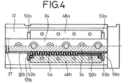
- Stoppers 37 are respectively mounted at one end of grooves 36a and 36b to prevent roller bearings 54 (described later) from exiting from the grooves 36a and 36b (see FIG. 4).
- the stroke control mechanism 24 is accommodated within the cover 38 mounted to the cylinder body 12 and has stopper blocks 42a and 42b bracketing a shuttle block 40 which is fixed to a side of slide table 14.
- the stopper blocks 42a and 42b are respectively secured to predetermined positions of the cylinder body 12.
- the shuttle block 40 has adjustable, threaded screws 46a and 46b provided at opposed ends thereof orientated along the direction of displacement of slide table 14, and a slit 44 defined centrally and transversely therein.
- guide members 48a and 48b are mounted to the underside of table 14 within the concave portion defined therein.
- the guide members 48a and 48b respectively have 90° V-shaped grooves 50a and 50b defined therein in an opposing relationship to respective grooves 36a and 36b of the guide rail 34, so as to form two longitudinal channels 49a and 49b.
- Channels 49a and 49b are approximately square in cross-section to accommodate roller bearings 54.
- stoppers 52a, 52b, 53a and 53b are threadedly mounted by screws 55a and 55b at their corresponding ends of the grooves 50a and 50b of the guide members 48a and 48b.
- the roller bearings 54 are not provided over the entire length of the channels 49a and 49b.
- the number of roller bearings is selected so that the roller bearings 54 freely roll within the channels 49a and 49b (i.e. with separations between individual roller bearings 54), and are preferably even in number in each of channels 49a and 49b.
- the roller bearings 54 are fitted within the channels 49a and 49b in alternating 45° angles from the vertical, i.e. alternating 90° by 90° to one another. Gaps and slots are provided to facilitate the rolling of the roller bearings 54 within such channels 49a and 49b, as follows.
- the horizontal gap?? extending vertically between opposed sides of guide rail 34 and associated respective portions of guide members 48a and 48b, provide a clearance for one set of opposed peripheral edges to free roll within.
- Longitudinally extending slots 37a, 37b, 51a and 51b are respectively provided at the opposed apexes of the grooves 36a, 36b, 50a and 50b.
- the other set of opposed peripheral edges of the inclined roller bearings 54 move freely within the clearances provided by slots 37a, 51a and 37b, 51b.
- the guide mechanism 13 includes the guide rail 34 with grooves 36a and 36b, interacting with guide members 48a and 48b with grooves 50a and 50b, thereby defining channels 49a and 49b in which a plurality of cylindrical roller bearings 54 freely roll in alternating orientation.
- ports 56 and 58 are defined in the head cover 18 for coupling to a compressed-air supply source through an unillustrated directional control valve. As seen in FIGS. 2 and 3, the port 56 communicates with cylinder chamber 16a through a narrow passage 59 defined in the head cover 18, the fluid passage 17 and then passage 15. Chamber 16a and chamber 16b communicate by passages 25. The port 58 communicates directly with the cylinder chamber 16b through bushing 21b.
- the slide actuator 10 constructed as described above, is actuated in the following manner.
- Fluid pressure is supplied from the unillustrated compressed-air supply source to the cylinder chambers 16a and 16b, alternating through ports 56 and 58, to reciprocate the pistons 26a and 26b.
- the rods 28a and 28b, the end plate 30 and the slide table 14 are also reciprocated following the reciprocating pistons 26a and 26b.
- the screws 46a and 46b of the stroke control mechanism 24 are respectively brought into abutment against the stopper blocks 42a and 42b, thereby making it possible to control the amount of displacement of the pistons 26a and 26b.
- Guide members 48a and 48b and the slide table 14 can be smoothly displaced because the roller bearings 54 of the guide mechanism 13 are smoothly rolled.
- the roller bearings 54 divide each of loads F acting thereon from the slide table 14 (not illustrated for simplification) through the guide members 48a and 48b, into F1 and F2. Accordingly, the area at which each of the roller bearings 54 contacts the grooves 50a and 50b, is large compared with only the point-to-point contacts between a conventional slide actuator sliding on spherical bearings. Therefore, the acting loads can be dispersed and supported on roller bearings 54 of relatively small size.
- Slots 51a, 51b, 37a and 37b extending along the apexes of grooves 50a, 50b, 36a and 36b, facilitate the free rolling of the roller bearings 54 by providing a clearance for the edges of the roller bearings 54 closest to respective apexes of the grooves 50a, 50b, 36a and 36b.
- the above-described slide actuator 10 has the following advantages. Since the load is supported by the circumferential surfaces of the roller bearings 54 acting on the planar surfaces of the grooves 50a, 50b, 36a and 36b, the pressure-receiving areas are increased. Accordingly, the slide actuator 10 can be reduced in size. Further, since the roller bearings 54 are orientated alternately, inclined 90° by 90°, and if there is an equal and even number of roller bearings 54 alternated in each channel 49a and 49b, then the total surface of contact in the F1 and F2 directions, is equal. As a result, the roller bearings 54 can effectively share and support the load irrespective of the direction in which the load is applied.
- the stroke control mechanism 24 is mounted to the side of the cylinder body 12, the slide table 14 can be positioned with high accuracy.
- the end plate 30 and the slide table 14 are integrally fixed or formed, and the cross section of the slide table 14 is shaped in the form of an inverted U-shaped recess so as to increase its rigidity, the rods 28a and 28b are not bent by the load of a work is mounted to the end plate 30.
- a slide actuator 60 according to a second embodiment will next be described below with reference to FIGS. 6 and 7. Elements of structure in the slide actuator 60, which are substantially identical to those employed in the slide actuator 10 according to the first embodiment, are identified by like reference numerals and their detailed description will therefore be omitted. Subsequent embodiments will also be treated in the same manner as described above.
- ports 62 and 64 corresponding to the ports 56 and 58 employed in the first embodiment, are defined in one side of a cylinder body 12, and communicate with chamber 16a, and also with cylinder chamber 16b through passages 65a and 65b. Further, respective ends of cylinder chambers 16a and 16b are closed or blocked by stoppers 66a and 66b respectively. Therefore, the slide actuator 60 does not need the head cover 18 having the ports 56 and 58 defined therein, as in the first embodiment. Also, end plate 30 has an hole 68 therethrough profiled to accept the leading end portion of guide rail 34 (as seen in FIG. 6) at one end of the piston stroke.
- the slide actuator 70 is constructed by mounting a stroke control mechanism 72 (having a function substantially identical to that of the stroke control mechanism 24 employed in the first embodiment) to the slide actuator 60 employed in the second embodiment.
- the stroke control mechanism 72 comprises a stopper block 76 attached to the side of a cylinder body 12 at one end thereof, a shuttle block 74 mounted to a side of the slide table 14 at the far end thereof, and a screw 78 and nut combination 80 threadedly inserted into stopper block 76.
- the slide table 14 is stopped when the shuttle block 74 abuts against the leading end of the screw 78 (not shown).
- the stroke of the slide table 14 can be finely adjusted by rotating the screw 78.
- a connecting plate 84 is mounted on the slide table 14 and an air chuck 86 is mounted on the connecting plate 84, as shown in FIG. 9.
- the air chuck 86 opens and closes grippers 88a and 88b in parallel under the action of air pressure or the like to grip a work or the like.
- compressed air is introduced into cylinder chambers 16a and 16b through one port 64, for example so as to move forward or advance pistons 26a and 26b, and thereby the slide table 14.
- rods 28a and 28b reach the forward end, the work is gripped by the grippers 88a and 88b of the air chuck 86. Compressed air is then introduced into the cylinder chambers 16a and 16b through the other port 62.
- FIG. 10 shows a slide actuator 90 according to a fourth embodiment, which is convenient for mounting to a wall or like flat surface, in association with screws 100a and 100b, having respectively screw heads 102a and 102b.
- the slide actuator 90 has: a cylinder body 12 having threaded holes 92a and 92b defined therethrough; a guide rail 34 mounted on cylinder body 12, which has a through hole 94 defined therethrough, whose diameter is larger than that of each of the threaded holes 92a and 92b; and a slide table 14 having through holes 96a and 96b therethrough, each having the same diameter as that of through hole 94 and a diameter larger than that of each of screw heads 102a and 102b.
- Holes 92a, 92b, 94, 96a, 96b are all oriented in the same direction, being orthogonal to the longitudinal axis of their respective associated components, cylinder body 12, guide rail 34 and slide table 14. Actually, other diameters of the various holes are possible, as long as the through hole(s) has a diameter larger than the associated screw head.
- Mounting actuator 90 to a wall is effected in the following manner.
- the bottom of the cylinder body 12 is brought into abutment against the surface of the wall and the slide table 14 is maintained in its back position, to effect the coincidence of holes, described above.
- screws 100a and 100b are respectively threadedly inserted into their corresponding threaded holes 92a and 92b through the through hole 96a and the through holes 96b and 94 respectively.
- Screws 100a and 100b are then further threaded so that their leading ends are inserted into the wall surface, to securely mount the slide actuator 90 to the wall and to position screw heads 102a and 102b respectively extend through the through holes 96a and 96b.
- the screw head 102a is forcibly positioned against the cylinder body 12.
- the screw head 102b is forcibly positioned against cylinder body 12, completely within the through hole 94 of the guide rail 34. That is, screw head 102b lies below the path of slide table 14.
- the screw heads 102a and 102b do not interfere with such travel.
- the slide actuator according to the present invention brings the following advantages.
- the load is supported by cylindrical roller bearings fitted within channels defined by grooves of two guide members and a guide rail. That is, the circumferential surfaces of the rollers are brought into contact with respective planes of the first and second grooves.
- sufficient area at which the rollers make contact with the guide members is provided so that the rollers can support a large load.
- the slide actuator can be manufactured small and light weight.
- holes can be defined in the cylinder body to coincide with through holes defined in the slide table.
- the cylinder body can be fixed to a wall surface or the like by threadedly inserting fixing members into the fixing holes via the through holes.
Landscapes
- Engineering & Computer Science (AREA)
- General Engineering & Computer Science (AREA)
- Mechanical Engineering (AREA)
- Actuator (AREA)
- Bearings For Parts Moving Linearly (AREA)
Priority Applications (1)
| Application Number | Priority Date | Filing Date | Title |
|---|---|---|---|
| DE9321593U DE9321593U1 (de) | 1992-12-24 | 1993-06-18 | Gleitstellglied |
Applications Claiming Priority (3)
| Application Number | Priority Date | Filing Date | Title |
|---|---|---|---|
| JP8843492 | 1992-12-24 | ||
| JP1992088434U JP2586276Y2 (ja) | 1991-12-26 | 1992-12-24 | スライドアクチュエータ |
| JP88434/92 | 1992-12-24 |
Publications (4)
| Publication Number | Publication Date |
|---|---|
| EP0603459A2 true EP0603459A2 (de) | 1994-06-29 |
| EP0603459A3 EP0603459A3 (de) | 1995-06-07 |
| EP0603459B1 EP0603459B1 (de) | 1997-10-01 |
| EP0603459B2 EP0603459B2 (de) | 2000-10-18 |
Family
ID=13942695
Family Applications (1)
| Application Number | Title | Priority Date | Filing Date |
|---|---|---|---|
| EP93109735A Expired - Lifetime EP0603459B2 (de) | 1992-12-24 | 1993-06-18 | Gleitstellglied |
Country Status (4)
| Country | Link |
|---|---|
| US (1) | US5363741A (de) |
| EP (1) | EP0603459B2 (de) |
| KR (1) | KR960014636B1 (de) |
| DE (1) | DE69314294T3 (de) |
Cited By (8)
| Publication number | Priority date | Publication date | Assignee | Title |
|---|---|---|---|---|
| EP0683010A1 (de) * | 1994-05-18 | 1995-11-22 | Smc Kabushiki Kaisha | Antriebsgerät mit Schlittentisch |
| WO2001068315A1 (de) * | 2000-03-17 | 2001-09-20 | Festo Ag & Co. | Linearantriebseinheit |
| GB2370319A (en) * | 2000-11-18 | 2002-06-26 | Passenger Lift Services Ltd | Single-feed tandem cylinder |
| DE10047391C2 (de) * | 1999-10-01 | 2002-10-02 | Smc Corp | Linearstellglied mit Luftdämpfungsmechanismus |
| DE19720100C2 (de) * | 1996-08-13 | 2003-03-27 | Smc Kk | Linearstellglied |
| DE10145811B4 (de) * | 2000-09-21 | 2006-11-02 | Smc Corp. | Linearstellglied mit Luftdämpfungsmechanismus |
| CN104863921A (zh) * | 2015-05-27 | 2015-08-26 | 浙江亿太诺气动科技有限公司 | 一种多面安装气动侧滑台 |
| EP4119085A4 (de) * | 2020-04-17 | 2023-04-26 | Riverfield Inc. | Pneumatischer antriebsmechanismus für medizinischen roboter |
Families Citing this family (31)
| Publication number | Priority date | Publication date | Assignee | Title |
|---|---|---|---|---|
| US5570769A (en) * | 1992-12-14 | 1996-11-05 | Turn Act, Inc. | Linear and rotary actuator combination |
| GB2276343B (en) * | 1993-03-26 | 1997-08-13 | Enomoto Co Ltd | Press die set and guide arrangement |
| US5676038A (en) * | 1993-10-12 | 1997-10-14 | Smc Kabushiki Kaisha | Actuator with slide table |
| USD373363S (en) | 1994-05-18 | 1996-09-03 | Smc Kabushiki Kaisha | Air cylinder with a slide table |
| US5568982A (en) * | 1994-10-14 | 1996-10-29 | Festo Kg | Linear drive |
| JP3896550B2 (ja) * | 1994-11-24 | 2007-03-22 | Smc株式会社 | リニアアクチュエータ |
| USD407409S (en) | 1995-07-07 | 1999-03-30 | Smc Corporation | Rodless cylinder |
| AU2679597A (en) * | 1996-04-22 | 1997-11-12 | Tol-O-Matic Inc. | Slot bearing |
| USD409625S (en) * | 1997-04-21 | 1999-05-11 | Howa Machinery, Ltd. | Rodless cylinder with a slider |
| USD404039S (en) | 1997-04-30 | 1999-01-12 | Smc Corporation | Cylinder with a position detector |
| USD441381S1 (en) | 1999-10-18 | 2001-05-01 | Smc Corporation | Switching assembly for fluid pressure actuator |
| JP3618264B2 (ja) * | 1999-10-18 | 2005-02-09 | Smc株式会社 | エスケープメントシリンダ |
| US6756707B2 (en) * | 2001-01-26 | 2004-06-29 | Tol-O-Matic, Inc. | Electric actuator |
| USD462330S1 (en) | 2001-01-26 | 2002-09-03 | Smc Kabushiki Kaisha | Magnetic switch |
| DE60335031D1 (de) * | 2003-01-28 | 2010-12-30 | Koganei Ltd | Befestigter anordnungskörper, verbinder und hydraulikzylindereinheit |
| WO2005067674A2 (en) * | 2004-01-08 | 2005-07-28 | Tol-O-Matic, Inc. | Electric actuator |
| ATE327076T1 (de) * | 2004-03-01 | 2006-06-15 | Festo Ag & Co | Linearantrieb mit einem von zwei führungseinheiten flankierten schlitten |
| ATE327075T1 (de) * | 2004-03-01 | 2006-06-15 | Festo Ag & Co | Linearantrieb |
| JP4587105B2 (ja) * | 2005-05-18 | 2010-11-24 | Smc株式会社 | リニアアクチュエータ及びその加工方法 |
| US8196484B2 (en) * | 2008-04-18 | 2012-06-12 | Tol-O-Matic, Inc. | Electric actuator |
| JP5574152B2 (ja) * | 2010-01-05 | 2014-08-20 | Smc株式会社 | リニアアクチュエータ |
| US8955424B2 (en) * | 2010-01-05 | 2015-02-17 | Smc Kabushiki Kaisha | Linear actuator |
| US9431868B2 (en) * | 2010-01-19 | 2016-08-30 | Tolomatic, Inc. | Manual override device for an electric actuator and method for use |
| JP5664843B2 (ja) | 2010-04-07 | 2015-02-04 | Smc株式会社 | リニアアクチュエータ |
| US8701513B2 (en) | 2010-07-14 | 2014-04-22 | Tol-O-Matic, Inc. | Screw driven linear actuator and housing assembly |
| KR101315397B1 (ko) * | 2012-03-13 | 2013-10-07 | 주식회사 피브이디 | 이동챔버를 구비한 유기물 승화 정제장치 |
| KR101491693B1 (ko) * | 2013-06-27 | 2015-02-10 | 이관종 | 유압 실린더 |
| CN105757040A (zh) * | 2016-01-20 | 2016-07-13 | 张奎国 | 绳锯机恒定张紧力收绳轨道 |
| DE102018215772A1 (de) * | 2018-09-17 | 2020-03-19 | Skf Motion Technologies Ab | Hilfsmontagevorrichtung |
| KR102836684B1 (ko) * | 2018-11-27 | 2025-07-21 | 티에치케이 가부시끼가이샤 | 운동 안내 장치 |
| CN110374959B (zh) * | 2019-06-18 | 2020-06-30 | 必成玻璃纤维(昆山)有限公司 | 一种固定牢固的丝杆气压缸固定座 |
Family Cites Families (17)
| Publication number | Priority date | Publication date | Assignee | Title |
|---|---|---|---|---|
| US1687369A (en) * | 1928-10-09 | Hydraulic broachiito machine | ||
| GB197901A (en) * | 1922-05-19 | 1923-07-05 | L Avebene Soc | Improvements relating to fuel briquettes |
| US3439581A (en) † | 1966-08-15 | 1969-04-22 | Res Designing Services Inc | Slide unit |
| US3778121A (en) * | 1971-11-18 | 1973-12-11 | Brown & Sharpe Manuf Co | Slide guide having preloaded hollow and solid roller bearings |
| FR2206542B1 (de) * | 1972-11-15 | 1976-10-29 | Thomson Csf | |
| US3960413A (en) * | 1972-11-17 | 1976-06-01 | Hydrel A.G. | Series roll body conveyance |
| US3994539A (en) † | 1975-07-22 | 1976-11-30 | Robomation Corporation | Self-contained activated slide apparatus and methods of constructing and utilizing same |
| US4013280A (en) * | 1976-08-09 | 1977-03-22 | Anwar Chitayat | Workpiece positioning table |
| EP0134398B1 (de) * | 1983-08-27 | 1988-07-20 | Franco Toss | Bausteinartiger kolbenbetriebener Linearantrieb |
| DE3490730T1 (de) † | 1984-07-11 | 1986-11-20 | Shoketsu Kinzoku Kogyo K.K., Tokio/Tokyo | Gleitzylinder |
| JPS62159811A (ja) * | 1985-12-30 | 1987-07-15 | Nippon Thompson Co Ltd | Af−f面円筒ころを使用した直線運動用ころ軸受 |
| JPH0440012Y2 (de) † | 1986-05-20 | 1992-09-18 | ||
| US4796516A (en) * | 1986-12-22 | 1989-01-10 | Licencia Talalmanyokat Ertekesito Es Innovacios | Actuator providing guided linear displacement |
| DE3874248D1 (de) † | 1987-07-10 | 1992-10-08 | Gregory C Hirschmann | Lineareinheit fuer eine montage-einrichtung der handhabungstechnik. |
| US4829880A (en) * | 1987-08-11 | 1989-05-16 | Adams Rite Products, Inc. | Fluid powered linear slide |
| DE9015336U1 (de) † | 1990-11-08 | 1991-02-14 | Gemotec Entwicklungs- und Fertigungsbetrieb für Montagetechnik GmbH, 8110 Hofheim Post Murnau | Linearmodul zur Ausführung von Linearbewegungen |
| DE4111202C2 (de) † | 1991-04-06 | 1995-06-08 | Bosch Gmbh Robert | Druckmittelbetätigte Lineareinheit |
-
1993
- 1993-06-17 US US08/077,608 patent/US5363741A/en not_active Expired - Lifetime
- 1993-06-18 EP EP93109735A patent/EP0603459B2/de not_active Expired - Lifetime
- 1993-06-18 DE DE69314294T patent/DE69314294T3/de not_active Expired - Lifetime
- 1993-06-25 KR KR1019930011681A patent/KR960014636B1/ko not_active Expired - Lifetime
Cited By (13)
| Publication number | Priority date | Publication date | Assignee | Title |
|---|---|---|---|---|
| EP0683010A1 (de) * | 1994-05-18 | 1995-11-22 | Smc Kabushiki Kaisha | Antriebsgerät mit Schlittentisch |
| DE19720100C2 (de) * | 1996-08-13 | 2003-03-27 | Smc Kk | Linearstellglied |
| DE10047391C2 (de) * | 1999-10-01 | 2002-10-02 | Smc Corp | Linearstellglied mit Luftdämpfungsmechanismus |
| DE10013195B4 (de) * | 2000-03-17 | 2008-05-21 | Festo Ag & Co. | Linearantriebseinheit |
| WO2001068315A1 (de) * | 2000-03-17 | 2001-09-20 | Festo Ag & Co. | Linearantriebseinheit |
| DE10013195A1 (de) * | 2000-03-17 | 2001-09-27 | Festo Ag & Co | Linearantriebseinheit |
| US6792845B2 (en) | 2000-03-17 | 2004-09-21 | Festo Ag & Co. | Linear drive unit |
| DE10145811B4 (de) * | 2000-09-21 | 2006-11-02 | Smc Corp. | Linearstellglied mit Luftdämpfungsmechanismus |
| GB2370319A (en) * | 2000-11-18 | 2002-06-26 | Passenger Lift Services Ltd | Single-feed tandem cylinder |
| CN104863921A (zh) * | 2015-05-27 | 2015-08-26 | 浙江亿太诺气动科技有限公司 | 一种多面安装气动侧滑台 |
| CN104863921B (zh) * | 2015-05-27 | 2017-01-04 | 浙江亿太诺气动科技有限公司 | 一种多面安装气动侧滑台 |
| EP4119085A4 (de) * | 2020-04-17 | 2023-04-26 | Riverfield Inc. | Pneumatischer antriebsmechanismus für medizinischen roboter |
| US12023115B2 (en) | 2020-04-17 | 2024-07-02 | Riverfield Inc. | Medical-robot pneumatic drive mechanism |
Also Published As
| Publication number | Publication date |
|---|---|
| DE69314294T3 (de) | 2001-05-17 |
| EP0603459B2 (de) | 2000-10-18 |
| KR940015332A (ko) | 1994-07-20 |
| EP0603459A3 (de) | 1995-06-07 |
| DE69314294T2 (de) | 1998-03-19 |
| EP0603459B1 (de) | 1997-10-01 |
| KR960014636B1 (ko) | 1996-10-19 |
| US5363741A (en) | 1994-11-15 |
| DE69314294D1 (de) | 1997-11-06 |
Similar Documents
| Publication | Publication Date | Title |
|---|---|---|
| US5363741A (en) | Slide actuator | |
| KR0180961B1 (ko) | 선형 액츄에이터 | |
| US4773770A (en) | Linear guide apparatus | |
| US6014924A (en) | Slide drive arrangement | |
| US4607873A (en) | Gripper apparatus | |
| KR0147727B1 (ko) | 슬라이드 테이블을 갖춘 액츄에이터 | |
| EP0704275B1 (de) | Linearantrieb | |
| US4773769A (en) | Slide structure and method of assembly thereof | |
| US5537912A (en) | Bearing adjusting mechanism for rodless cylinder | |
| US5311810A (en) | Rodless cylinder | |
| CN101311557A (zh) | 线性致动器 | |
| US5522607A (en) | Chuck mechanism | |
| US5483868A (en) | Braking apparatus for a rodless piston actuated reciprocating carriage | |
| JPH0592505U (ja) | スライドアクチュエータ | |
| JP2613337B2 (ja) | ロッドレスシリンダ | |
| EP0472778B1 (de) | Lineareinheit | |
| KR100515268B1 (ko) | 공작기계의 선형안내장치 | |
| US20020041065A1 (en) | Adjustable guide system for jaws of fluid-operated grippers | |
| JP3775866B2 (ja) | リニアアクチュエータ | |
| DE29807438U1 (de) | Magnetisch vorgespannte Linearführung | |
| DE9321593U1 (de) | Gleitstellglied | |
| JP2565979Y2 (ja) | スライドアクチュエータ | |
| JP3755553B2 (ja) | スライドシリンダ | |
| JP3432766B2 (ja) | リニアアクチュエータ | |
| SU1161316A1 (ru) | Самоцентрирующий люнет |
Legal Events
| Date | Code | Title | Description |
|---|---|---|---|
| PUAI | Public reference made under article 153(3) epc to a published international application that has entered the european phase |
Free format text: ORIGINAL CODE: 0009012 |
|
| 17P | Request for examination filed |
Effective date: 19930626 |
|
| AK | Designated contracting states |
Kind code of ref document: A2 Designated state(s): DE FR GB IT |
|
| PUAL | Search report despatched |
Free format text: ORIGINAL CODE: 0009013 |
|
| AK | Designated contracting states |
Kind code of ref document: A3 Designated state(s): DE FR GB IT |
|
| 17Q | First examination report despatched |
Effective date: 19960401 |
|
| GRAG | Despatch of communication of intention to grant |
Free format text: ORIGINAL CODE: EPIDOS AGRA |
|
| GRAH | Despatch of communication of intention to grant a patent |
Free format text: ORIGINAL CODE: EPIDOS IGRA |
|
| GRAH | Despatch of communication of intention to grant a patent |
Free format text: ORIGINAL CODE: EPIDOS IGRA |
|
| GRAA | (expected) grant |
Free format text: ORIGINAL CODE: 0009210 |
|
| AK | Designated contracting states |
Kind code of ref document: B1 Designated state(s): DE FR GB IT |
|
| REF | Corresponds to: |
Ref document number: 69314294 Country of ref document: DE Date of ref document: 19971106 |
|
| ET | Fr: translation filed | ||
| ITF | It: translation for a ep patent filed | ||
| PLBQ | Unpublished change to opponent data |
Free format text: ORIGINAL CODE: EPIDOS OPPO |
|
| PLBI | Opposition filed |
Free format text: ORIGINAL CODE: 0009260 |
|
| PLBF | Reply of patent proprietor to notice(s) of opposition |
Free format text: ORIGINAL CODE: EPIDOS OBSO |
|
| 26 | Opposition filed |
Opponent name: FESTO AG & CO Effective date: 19980616 |
|
| PLBF | Reply of patent proprietor to notice(s) of opposition |
Free format text: ORIGINAL CODE: EPIDOS OBSO |
|
| PLBF | Reply of patent proprietor to notice(s) of opposition |
Free format text: ORIGINAL CODE: EPIDOS OBSO |
|
| PLAW | Interlocutory decision in opposition |
Free format text: ORIGINAL CODE: EPIDOS IDOP |
|
| PLAW | Interlocutory decision in opposition |
Free format text: ORIGINAL CODE: EPIDOS IDOP |
|
| PUAH | Patent maintained in amended form |
Free format text: ORIGINAL CODE: 0009272 |
|
| STAA | Information on the status of an ep patent application or granted ep patent |
Free format text: STATUS: PATENT MAINTAINED AS AMENDED |
|
| 27A | Patent maintained in amended form |
Effective date: 20001018 |
|
| AK | Designated contracting states |
Kind code of ref document: B2 Designated state(s): DE FR GB IT |
|
| ET3 | Fr: translation filed ** decision concerning opposition | ||
| ITF | It: translation for a ep patent filed | ||
| REG | Reference to a national code |
Ref country code: GB Ref legal event code: IF02 |
|
| PGFP | Annual fee paid to national office [announced via postgrant information from national office to epo] |
Ref country code: IT Payment date: 20090623 Year of fee payment: 17 Ref country code: FR Payment date: 20090615 Year of fee payment: 17 |
|
| PGFP | Annual fee paid to national office [announced via postgrant information from national office to epo] |
Ref country code: GB Payment date: 20090618 Year of fee payment: 17 |
|
| GBPC | Gb: european patent ceased through non-payment of renewal fee |
Effective date: 20100618 |
|
| REG | Reference to a national code |
Ref country code: FR Ref legal event code: ST Effective date: 20110228 |
|
| PG25 | Lapsed in a contracting state [announced via postgrant information from national office to epo] |
Ref country code: IT Free format text: LAPSE BECAUSE OF NON-PAYMENT OF DUE FEES Effective date: 20100618 |
|
| PG25 | Lapsed in a contracting state [announced via postgrant information from national office to epo] |
Ref country code: FR Free format text: LAPSE BECAUSE OF NON-PAYMENT OF DUE FEES Effective date: 20100630 |
|
| PG25 | Lapsed in a contracting state [announced via postgrant information from national office to epo] |
Ref country code: GB Free format text: LAPSE BECAUSE OF NON-PAYMENT OF DUE FEES Effective date: 20100618 |
|
| PGFP | Annual fee paid to national office [announced via postgrant information from national office to epo] |
Ref country code: DE Payment date: 20120622 Year of fee payment: 20 |
|
| REG | Reference to a national code |
Ref country code: DE Ref legal event code: R071 Ref document number: 69314294 Country of ref document: DE |
|
| REG | Reference to a national code |
Ref country code: DE Ref legal event code: R071 Ref document number: 69314294 Country of ref document: DE |
|
| PG25 | Lapsed in a contracting state [announced via postgrant information from national office to epo] |
Ref country code: DE Free format text: LAPSE BECAUSE OF EXPIRATION OF PROTECTION Effective date: 20130619 |