EP0603473A2 - Thermische Tintenstrahlfeder mit einer Plastik/Metall-Befestigung für die Hülle - Google Patents
Thermische Tintenstrahlfeder mit einer Plastik/Metall-Befestigung für die Hülle Download PDFInfo
- Publication number
- EP0603473A2 EP0603473A2 EP93114942A EP93114942A EP0603473A2 EP 0603473 A2 EP0603473 A2 EP 0603473A2 EP 93114942 A EP93114942 A EP 93114942A EP 93114942 A EP93114942 A EP 93114942A EP 0603473 A2 EP0603473 A2 EP 0603473A2
- Authority
- EP
- European Patent Office
- Prior art keywords
- cover
- frame structure
- tabs
- ink
- frame
- Prior art date
- Legal status (The legal status is an assumption and is not a legal conclusion. Google has not performed a legal analysis and makes no representation as to the accuracy of the status listed.)
- Granted
Links
Images


Classifications
-
- B—PERFORMING OPERATIONS; TRANSPORTING
- B41—PRINTING; LINING MACHINES; TYPEWRITERS; STAMPS
- B41J—TYPEWRITERS; SELECTIVE PRINTING MECHANISMS, i.e. MECHANISMS PRINTING OTHERWISE THAN FROM A FORME; CORRECTION OF TYPOGRAPHICAL ERRORS
- B41J2/00—Typewriters or selective printing mechanisms characterised by the printing or marking process for which they are designed
- B41J2/005—Typewriters or selective printing mechanisms characterised by the printing or marking process for which they are designed characterised by bringing liquid or particles selectively into contact with a printing material
- B41J2/01—Ink jet
- B41J2/17—Ink jet characterised by ink handling
- B41J2/175—Ink supply systems ; Circuit parts therefor
- B41J2/17503—Ink cartridges
- B41J2/17513—Inner structure
-
- B—PERFORMING OPERATIONS; TRANSPORTING
- B41—PRINTING; LINING MACHINES; TYPEWRITERS; STAMPS
- B41J—TYPEWRITERS; SELECTIVE PRINTING MECHANISMS, i.e. MECHANISMS PRINTING OTHERWISE THAN FROM A FORME; CORRECTION OF TYPOGRAPHICAL ERRORS
- B41J29/00—Details of, or accessories for, typewriters or selective printing mechanisms not otherwise provided for
- B41J29/12—Guards, shields or dust excluders
- B41J29/13—Cases or covers
-
- Y—GENERAL TAGGING OF NEW TECHNOLOGICAL DEVELOPMENTS; GENERAL TAGGING OF CROSS-SECTIONAL TECHNOLOGIES SPANNING OVER SEVERAL SECTIONS OF THE IPC; TECHNICAL SUBJECTS COVERED BY FORMER USPC CROSS-REFERENCE ART COLLECTIONS [XRACs] AND DIGESTS
- Y10—TECHNICAL SUBJECTS COVERED BY FORMER USPC
- Y10T—TECHNICAL SUBJECTS COVERED BY FORMER US CLASSIFICATION
- Y10T29/00—Metal working
- Y10T29/49—Method of mechanical manufacture
- Y10T29/49401—Fluid pattern dispersing device making, e.g., ink jet
-
- Y—GENERAL TAGGING OF NEW TECHNOLOGICAL DEVELOPMENTS; GENERAL TAGGING OF CROSS-SECTIONAL TECHNOLOGIES SPANNING OVER SEVERAL SECTIONS OF THE IPC; TECHNICAL SUBJECTS COVERED BY FORMER USPC CROSS-REFERENCE ART COLLECTIONS [XRACs] AND DIGESTS
- Y10—TECHNICAL SUBJECTS COVERED BY FORMER USPC
- Y10T—TECHNICAL SUBJECTS COVERED BY FORMER US CLASSIFICATION
- Y10T29/00—Metal working
- Y10T29/49—Method of mechanical manufacture
- Y10T29/49826—Assembling or joining
- Y10T29/49863—Assembling or joining with prestressing of part
- Y10T29/49876—Assembling or joining with prestressing of part by snap fit
Definitions
- the present invention is related to the following commonly assigned pending U.S. patent applications: COMPACT FLUID COUPLER FOR THERMAL INK JET PRINT CARTRIDGE INK RESERVOIR, serial number 07/853,372, filed March 18, 1992, by James G. Salter et al.; INK PRESSURE REGULATOR FOR A THERMAL INK-JET PRINTER, serial number 07/928,811, filed August 12, 1992, by Tofigh Khodapanah et al.; COLLAPSIBLE INK RESERVOIR STRUCTURE AND PRINTER INK CARTRIDGE, serial number 07/929,615, filed August 12, 1992, by George T.
- the present invention relates to thermal ink-jet (TIJ) pens, and more particularly to a technique for attachment of a metal cover to the pen.
- TIJ technology is widely used in computer printers.
- a TIJ includes a print head typically comprising several tiny controllable ink-jets, which are selectively activated to release a jet or spray of ink from an ink reservoir onto the print media (such as paper) in order to create an image or portion of an image.
- TIJ printers are described, for example, in the Hewlett-Packard Journal, Volume 36, Number 5, May, 1985, and Volume 39, Number 4, August, 1988.
- An object of this invention is to provide a TIJ pen which includes an external pen frame structure fabricated of plastic, and a metal cover which is attached to the plastic frame structure to enclose an open region defined by the frame and protect an ink reservoir within the TIJ pen.
- a further object is to provide a technique for rigidly attaching a metal cover to a plastic frame without the use of adhesives, screws, thermal, or ultrasonic processes.
- a thermal ink-jet pen comprises an external pen frame structure fabricated of a plastic material and a metal cover attached to the frame structure.
- the frame structure defines the external periphery of the pen and large open regions at the sides thereof.
- An ink reservoir is mounted within the frame structure, and a thermal ink-jet printhead is coupled to the ink reservoir.
- the metal cover comprises a planar surface member for covering the open region defined by the frame. Means are provided for attaching the metal cover to the plastic frame structure, wherein the cover encloses the open region and protects the ink reservoir.
- the frame structure defines two large open regions, one on each pen side, and there are two metal covers attached to the frame, one covering each open region.
- the frame structure comprising a plurality of tab mating features.
- the metal cover comprises a planar surface and has a plurality of spaced metal tabs projecting from the planar surface for engagement with the mating features of the frame structure.
- the tabs are press fit into engagement with the mating features of the frame structure such that the tabs displace plastic on the mating features. As a result, the tabs become locked into the frame features, and thereby secure the cover to the frame structure without adhesives, screws, thermal, or ultrasonic processes.
- the tab includes an end portion which is enlarged with respect to the tab body, so that the end portion displaces plastic defining the mating features when the cover is attached.
- the mating features comprise a slot formed in the frame, the slot having a width dimension smaller than the enlarged end portion of the tab, wherein as the tab is press fit into the slot, plastic surrounding the slot is displaced.
- the slot further includes beveled sides presenting plastic material at the sides which is displaced as the tab is press fit into the slot.
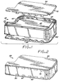
- FIGS. 1-9 illustrate a TIJ pen 50 embodying the invention.
- the pen comprises an external frame structure 60, and a pair of side covers 70 and 80.
- the frame 60 defines the external periphery of the pen 50 as a narrow, flat structure.
- the TIJ pen 50 provides many benefits for the printing system built to utilize it.
- the pen 50 is narrow reducing the required width of the printer carriage and therefore the total printer width.
- the pen 50 includes a simple and efficient ink delivery system, more fully described in the above-reference pending applications, serial nos. 07/928,811 and 07/929,615.
- ink is contained within a reservoir formed by two pieces of thin polyethylene bag material 62 bonded to a compatible plastic material on the frame 60.
- Two pistons and a spring (not shown) inside the bag provide backpressure to prevent ink from drooling out the printhead 52.
- the frame 60 is made of two different plastic materials.
- the first material is an engineering plastic forming the external surfaces and providing structural support.
- An exemplary plastic suitable for the purpose is polyphenyleneoxide (PPO).
- PPO polyphenyleneoxide
- the second plastic material provides the fluid path for the ink and is suitable for attachment of the bag material, as described more fully in the above-referenced pending application serial number 07/853,372.
- the covers 70 and 80 may be fabricated of any suitable material; in this exemplary embodiment, the covers are fabricate of metal.
- the thin metal side covers 70 and 80 protect the inside components, add considerable rigidity to the system, and allow for a high degree of volumetric efficiency.
- the covers 70 and 80 can be fabricated of a pre-processed metal, such as metal having a pre-painted surface or a PVC clad metal to provide an aesthetically complete appearance.
- the covers 70 and 80 must be rigid to prevent ink from being squeezed out in the event force is applied against the covers, e.g., during handling of the pen.
- An exemplary material from which the covers 70 and 80 may be fabricated is low carbon steel having a thickness of 0.019 inches.
- the metal covers 70 and 80 may be attached to the plastic frame 60 by adhesives or screw fasteners, or by use of thermal or ultrasonic processes.
- the problem of attaching a cover to a thin plastic frame is solved by designing a series of metal tabs on the covers that will lock onto mating plastic features on the frame.
- the tabs displace plastic on the mating features of the frame during assembly, allowing use of a simple mechanical press to assemble the covers to the frame, with no adhesives, screws, thermal or ultrasonic processes.
- the design of the cover tabs also enables them to lock into the frame; and the addition of chamfered corners on the tab aids assembly by providing a lead-in surface.
- the resulting cover/frame seam will resist shear, axial and transverse forces that occur in the joint as a result of externally applied loads to the pen.
- This joint allows for use of cosmetically suitable cover materials (e.g., pre-painted metal, PVC clad metal, or metals having a suitable cosmetic surface).
- the cover 70 includes a series of spaced tabs 72 which are designed to mate into corresponding dovetailed slot features 64 defined in the frame 60.
- the cover 80 is a mirror image of the cover 70, and also includes spaced metal tabs 82 which are designed to mate into corresponding dovetailed slot features (not shown) in an edge of the frame 60 similar to the slots 64. Because the attachment technique for the two covers 70 and 80 is identical, only the attachment of cover 70 will be described in detail.
- FIG. 2 shows the cover 70 attached to the frame 60, wherein the cover tabs have been partially press fit into the corresponding slot features 64 of the frame 60.
- the only assembly step remaining to the cover-frame configuration of FIG. 2 is to apply force to the cover to fully seat the tabs into the slot features.
- the frames 60 are preferably fabricated by injection molding. Typically the sides of a frame, before integration with the cover, will be bowed slightly inwardly. Similarly, the tabs 72 of a typical cover 70 after fabrication will not be bent exactly perpendicular to the cover surface, but will instead be bent outwardly to a degree.
- special tooling is employed. This tooling acts to force the top edges of the frame sides outwardly to receive the cover, and forces the tabs into a true perpendicular position relative to the cover surface. As a result, the tabs are properly aligned with the dovetailed slots 64 formed in the frame sides, and force can be applied to press fit the tabs into engagement with the slots. Exemplary tooling to accomplish these functions is shown in FIG. 3.
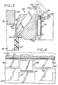
- FIG. 3 illustrates a mechanical press arrangement for press fitting the cover tabs into engagement with the slot features 64 of the frame 60, to result in the partially assembled cover-frame configuration as shown in FIG. 2.
- a tool 100 includes an arm 102 with an blade tip 104.
- a dogleg section 106 pivots about pivot point 108.
- the arm 102 and dogleg section 106 are connected by a pin 105 fixed to the section 106 and extending through a slot 107 formed in the arm 102.
- the arm 102 in turn rides in a slot 103 defined in tooling block 109.
- a double acting pneumatic cylinder 110 has a piston rod 112 which is connected to the intermediate area of the dogleg section at point 114. Actuation of the cylinder 110 then causes extension or retraction of the piston 112, thereby driving the dogleg section 106 to pivot upwardly or downwardly about the pivot point 108, in turn causing the arm 102 to slide upwardly or downwardly within slot 103.
- the tool 100 further includes an inclined block surface 116 and a vertical surface 117 which extends along the side of the cover. As the tabs 72 come into contact with these surfaces, those tabs which are splayed outwardly are bent into a perpendicular position relative to the cover surface.
- the blade tip 104 is employed to force the inwardly bowed top edge of the frame outwardly into alignment with the cover tabs.
- a press tool 120 is extended downwardly to contact the top surface of the cover 70, pressing the cover downwardly. At the commencement of the operation, the blade tip 104 is fully extended downwardly. The blade tip 104 is positioned so that it is intermediate two adjacent tabs 72.
- the cover 70 As the cover is pressed downwardly, the side of the frame 60 engages the blade tip 104, thereby applying pressure tending to bend the side outwardly as the cover is pressed downwardly. In the meantime, the tabs are aligned by engagement with the block surfaces 116 and 117, tending to align the tabs with the recessed features 64 formed in the frame 60. As the cover 70 continues to be pressed downwardly by the press tool 120, the blade tip 104 is withdrawn by actuation of the cylinder 110 to lift the blade tip away from engagement with the frame side, until the blade tip is fully retracted away from the side of the frame. This permits the cover 70 to be press fit into engagement with the frame features by continued downward pressure of the press tool 120.
- the press tool 120 does not apply sufficient force to fully seat the tabs into the slots 64, but rather only partially seats the tabs to the extent shown in FIG. 2.
- the partially assembled pen is then moved to another station where another press tool, capable of exerting a greater force, is applied to fully seat the tabs into the dovetailed slots.
- Another press tool capable of exerting a greater force, is applied to fully seat the tabs into the dovetailed slots.
- the press fitting of the tabs 72 into the dovetail slots 64 imparts great rigidity to the installed cover.
- blade elements 104 typically there will be a plurality of blade elements 104 for each side of the cover, disposed between adjacent recessed features of the frame, although a blade element is not required for each tab.
- tools 100 disposed along each side of the frame 60, each with multiple blade tip elements.
- the blade elements will typically be ganged together for actuation by a single cylinder 110.
- a press force of about 400 pounds is sufficient to properly attach the cover to the frame.
- FIG. 4 shows the position of the blade end 104 as the block 120 begins its downward motion.
- the blade end is disposed between adjacent recessed features 64 formed in the frame 60.
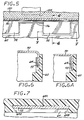
- FIG. 5 is a cross-sectional view taken along the same line as FIG. 4, but with the tabs 72 inserted into the features 64 of the frame 60.
- FIGS. 6 and 7 illustrate in more detail the manner in which the tabs have been seated into the features 64.
- FIG. 6 is a cross-section showing the cover which has been partially seated in the frame, as shown in FIGS. 2 and 5.
- FIG. 6A shows the cover after it has been fully seated, as described above.
- FIG. 7 shows the beveled side walls 64A, 64B which define the dovetailed slot features.
- the side walls 64A, 64B form an acute angle with the long wall 64C comprising the feature 64.
- the tab 72 has a width dimension selected so that plastic material comprising the frame 60 must be displaced by the side edges of the tab 72 in order for the tab to fully seat within the slot feature.
- the beveling of the side walls 64A, 64B serves to capture the tab within the feature.
- the tab side edges 72A and 72B are not exactly perpendicular to the cover, but taper outwardly slightly, so that the tab end region 72C has a width dimension which is larger than the width of the tab adjacent the cover 70.
- the tab tip also has beveled edges which serve to lead the tab into the feature 64.
- FIGS. 8 and 9 illustrate further the manner in which the tab 72 engages the feature 64.
- FIG. 8 shows the relatively wider width dimension of the tab tip than the width of the feature 64.
- FIG. 9 shows the tab engaged in the feature, with the side walls displacing plastic material at the edges of the feature 64.
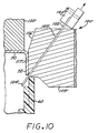
- FIG. 10 illustrates an alternate tool 100' which may be employed to assemble the cover 70 to the pen frame 60.
- the blade 102 has been replaced by a much thinner blade 102' which slidably fits into a narrow groove 103' formed in the tooling block 109'.
- the blade 102' is formed of a flexible high strength steel, much like the blades of a feeler gauge.
- the outer end of the blade 102' is connected to a connector block 150, which is connected to a drive element (not shown) which selectively pushes the blade down or pulls it away from the interface between the cover and the frame.
- the tool 100' operates in the same manner as the tool 100 (FIG. 3).
- the blade 102' forces the inwardly bowed top edge of the frame to an upright position, while the shoulder 116' forces the tabs 72 to the perpendicular position as shown.
- FIGS. 11-15 illustrate various alternative configurations of the tabs 72.
- FIGS. 11A and 11B illustrate a tab 200 wherein the tap tip 202 is curved with a lead-in radius to facilitate the mating of the tab with the feature formed in the frame. The tip of the tab 200 is reduced in width as well.
- FIG. 12 shows a tab 210 wherein the sides are parallel to each other, and perpendicular to the cover.
- FIG. 13 shows a tab 220 wherein the tab sides initially taper inwardly toward the tip, and taper outwardly to form a pointed bulged portions 222 and 224 adjacent each tip side.
- FIG. 14 shows a tab 230 employing half-circular cutouts 232 and 234 adjacent the tab tip.
- FIG. 15 shows a tab 240 wherein hook elements 242 and 244 are defined in each tab side to engage the frame feature.
- the technique of this invention for attaching a cover to the plastic frame of a TIJ requires a minimum of plastic on the frame yet imparts a high degree of structural integrity to the pen.
- Another advantage is that the cover may be attached to the frame using a simple mechanical press, and without the use of adhesives, screws, thermal, or ultrasonic processes.
- the cover tab mating features in the plastic frame can be formed using strong features in the mold consistent with efficiently established parting planes.
Landscapes
- Accessory Devices And Overall Control Thereof (AREA)
- Ink Jet (AREA)
Applications Claiming Priority (2)
| Application Number | Priority Date | Filing Date | Title |
|---|---|---|---|
| US994810 | 1992-12-22 | ||
| US07/994,810 US5610644A (en) | 1992-12-22 | 1992-12-22 | Thermal ink-jet pen with a plastic/metal attachment for the cover |
Publications (3)
| Publication Number | Publication Date |
|---|---|
| EP0603473A2 true EP0603473A2 (de) | 1994-06-29 |
| EP0603473A3 EP0603473A3 (de) | 1997-10-15 |
| EP0603473B1 EP0603473B1 (de) | 1999-12-08 |
Family
ID=25541081
Family Applications (1)
| Application Number | Title | Priority Date | Filing Date |
|---|---|---|---|
| EP93114942A Expired - Lifetime EP0603473B1 (de) | 1992-12-22 | 1993-09-16 | Thermische Tintenstrahlfeder mit einer Plastik/Metall-Befestigung für die Hülle |
Country Status (4)
| Country | Link |
|---|---|
| US (1) | US5610644A (de) |
| EP (1) | EP0603473B1 (de) |
| JP (1) | JP3670675B2 (de) |
| DE (1) | DE69327225T2 (de) |
Families Citing this family (7)
| Publication number | Priority date | Publication date | Assignee | Title |
|---|---|---|---|---|
| US6003984A (en) * | 1992-03-18 | 1999-12-21 | Hewlett-Packard Co. | Ink-jet swath printer with auxiliary ink reservoir |
| USD383488S (en) | 1995-03-30 | 1997-09-09 | Brother Kogyo Kabushiki Kaisha | Ink cartridge for ink jet printer |
| KR0144890B1 (ko) * | 1995-05-27 | 1998-07-15 | 김광호 | 더블 화면 티브이에서의 캡션과 문자 방송표시장치 및 방법 |
| US6183072B1 (en) | 1998-04-29 | 2001-02-06 | Hewlett-Packard Company | Seal using gasket compressed normal to assembly axis of two parts |
| US6527378B2 (en) | 2001-04-20 | 2003-03-04 | Hewlett-Packard Company | Thermal ink jet defect tolerant resistor design |
| US6595479B2 (en) * | 2001-05-15 | 2003-07-22 | Hubbell Incorporated | Electrical fixture mounting assembly |
| US7992961B2 (en) * | 2006-03-31 | 2011-08-09 | Brother Kogyo Kabushiki Kaisha | Ink-jet head |
Family Cites Families (9)
| Publication number | Priority date | Publication date | Assignee | Title |
|---|---|---|---|---|
| US3913774A (en) * | 1973-03-12 | 1975-10-21 | Leslie Vajtay | End caps for containers |
| JPS61131499A (ja) * | 1984-11-30 | 1986-06-19 | 株式会社東芝 | カバ−の取付構造 |
| US4739339A (en) * | 1986-02-14 | 1988-04-19 | Dataproducts Corporation | Cartridge and method of using a cartridge for phase change ink in an ink jet apparatus |
| JPH02187341A (ja) * | 1989-01-13 | 1990-07-23 | Canon Inc | インクジェットヘッドの保存容器 |
| US4931811A (en) * | 1989-01-31 | 1990-06-05 | Hewlett-Packard Company | Thermal ink jet pen having a feedtube with improved sizing and operational with a minimum of depriming |
| JP3222454B2 (ja) * | 1990-02-02 | 2001-10-29 | キヤノン株式会社 | インクタンクカートリッジ |
| EP0715958B1 (de) * | 1991-05-27 | 1998-08-12 | Seiko Epson Corporation | Tintenkassette für Tintenstrahlaufzeichnungsvorrichtung |
| US5464578A (en) * | 1992-03-18 | 1995-11-07 | Hewlett-Packard Company | Method of making a compact fluid coupler for thermal inkjet print cartridge ink reservoir |
| US5451995A (en) * | 1992-12-22 | 1995-09-19 | Hewlett-Packard Company | Rigid loop case structure for thermal ink-jet pen |
-
1992
- 1992-12-22 US US07/994,810 patent/US5610644A/en not_active Expired - Lifetime
-
1993
- 1993-09-16 DE DE69327225T patent/DE69327225T2/de not_active Expired - Lifetime
- 1993-09-16 EP EP93114942A patent/EP0603473B1/de not_active Expired - Lifetime
- 1993-12-22 JP JP34617293A patent/JP3670675B2/ja not_active Expired - Lifetime
Also Published As
| Publication number | Publication date |
|---|---|
| EP0603473B1 (de) | 1999-12-08 |
| JP3670675B2 (ja) | 2005-07-13 |
| DE69327225D1 (de) | 2000-01-13 |
| EP0603473A3 (de) | 1997-10-15 |
| DE69327225T2 (de) | 2000-07-13 |
| JPH06255095A (ja) | 1994-09-13 |
| US5610644A (en) | 1997-03-11 |
Similar Documents
| Publication | Publication Date | Title |
|---|---|---|
| DE69328737T2 (de) | Flüssigkeitsbehälter für Aufzeichnungsgerät | |
| US6390593B1 (en) | Foam-filled caps for sealing inkjet printheads | |
| DE69317679T2 (de) | Abdeckmechanismus für ein Tintenstrahlaufzeichnungsgerät | |
| US5610644A (en) | Thermal ink-jet pen with a plastic/metal attachment for the cover | |
| EP0591844B1 (de) | Regeneriermechanismus und ein Tintenstrahlgerät mit diesem Mechanismus | |
| DE69311884T2 (de) | Tintenstrahlkassette mit Doppelbehälter und optimalem Mundstück | |
| DE20122653U1 (de) | Tintenkartusche und diese verwendende Tintenstrahlaufzeichnungseinrichtung | |
| DE112005001041T5 (de) | Tintenbehälter, Druckkopf und Tintenstrahldruckgerät | |
| US5917526A (en) | Method and apparatus for ink container locking | |
| US7367663B2 (en) | Liquid container having a stirring chamber | |
| JP4150461B2 (ja) | 2部品の組立軸に垂直に圧縮されるガスケットを使用するシール | |
| DE69119179T2 (de) | Tintenstrahlaufzeichnungsgerät | |
| EP1219445B1 (de) | Tintenpatrone | |
| EP1007364B1 (de) | Tintenbehälter zur verwendung in einer druckvorrichtung mit einer tintenanzeigevorrichtung | |
| US6435675B2 (en) | Method for manufacturing ink tank, ink tank, ink jet cartridge, and ink jet recording apparatus | |
| US7360879B2 (en) | Inkjet pen adapter | |
| JP2003237107A (ja) | 液体噴射記録ヘッドおよび液体噴射記録装置 | |
| JP3117807B2 (ja) | インクジェットカートリッジの保管箱 | |
| JP3988257B2 (ja) | 画像形成装置およびカートリッジ部材 | |
| US20050275671A1 (en) | Duct connecting structure | |
| US7762794B2 (en) | Tube and tube pump | |
| EP0451846A2 (de) | Kappe für Rückgewinnungsgerät und Verfahren zur Rückgewinnung mittels Unterdruck | |
| JP3417414B2 (ja) | インクジェットプリンタのポンプ駆動方法 | |
| US7703881B2 (en) | Print head cleaning member | |
| KR102837673B1 (ko) | 인쇄장치용 오토커터모듈의 설치구조 및 이를 포함하는 인쇄장치 |
Legal Events
| Date | Code | Title | Description |
|---|---|---|---|
| PUAI | Public reference made under article 153(3) epc to a published international application that has entered the european phase |
Free format text: ORIGINAL CODE: 0009012 |
|
| AK | Designated contracting states |
Kind code of ref document: A2 Designated state(s): DE FR GB IT |
|
| PUAL | Search report despatched |
Free format text: ORIGINAL CODE: 0009013 |
|
| AK | Designated contracting states |
Kind code of ref document: A3 Designated state(s): DE FR GB IT |
|
| 17P | Request for examination filed |
Effective date: 19980316 |
|
| GRAG | Despatch of communication of intention to grant |
Free format text: ORIGINAL CODE: EPIDOS AGRA |
|
| GRAG | Despatch of communication of intention to grant |
Free format text: ORIGINAL CODE: EPIDOS AGRA |
|
| GRAH | Despatch of communication of intention to grant a patent |
Free format text: ORIGINAL CODE: EPIDOS IGRA |
|
| 17Q | First examination report despatched |
Effective date: 19990129 |
|
| GRAH | Despatch of communication of intention to grant a patent |
Free format text: ORIGINAL CODE: EPIDOS IGRA |
|
| GRAA | (expected) grant |
Free format text: ORIGINAL CODE: 0009210 |
|
| AK | Designated contracting states |
Kind code of ref document: B1 Designated state(s): DE FR GB IT |
|
| PG25 | Lapsed in a contracting state [announced via postgrant information from national office to epo] |
Ref country code: IT Free format text: LAPSE BECAUSE OF FAILURE TO SUBMIT A TRANSLATION OF THE DESCRIPTION OR TO PAY THE FEE WITHIN THE PRE;WARNING: LAPSES OF ITALIAN PATENTS WITH EFFECTIVE DATE BEFORE 2007 MAY HAVE OCCURRED AT ANY TIME BEFORE 2007. THE CORRECT EFFECTIVE DATE MAY BE DIFFERENT FROM THE ONE RECORDED.SCRIBED TIME-LIMIT Effective date: 19991208 Ref country code: FR Free format text: LAPSE BECAUSE OF FAILURE TO SUBMIT A TRANSLATION OF THE DESCRIPTION OR TO PAY THE FEE WITHIN THE PRESCRIBED TIME-LIMIT Effective date: 19991208 |
|
| REF | Corresponds to: |
Ref document number: 69327225 Country of ref document: DE Date of ref document: 20000113 |
|
| EN | Fr: translation not filed | ||
| PLBE | No opposition filed within time limit |
Free format text: ORIGINAL CODE: 0009261 |
|
| 26N | No opposition filed | ||
| REG | Reference to a national code |
Ref country code: GB Ref legal event code: 732E |
|
| REG | Reference to a national code |
Ref country code: GB Ref legal event code: IF02 |
|
| REG | Reference to a national code |
Ref country code: GB Ref legal event code: 732E Free format text: REGISTERED BETWEEN 20120329 AND 20120404 |
|
| PGFP | Annual fee paid to national office [announced via postgrant information from national office to epo] |
Ref country code: GB Payment date: 20120925 Year of fee payment: 20 |
|
| PGFP | Annual fee paid to national office [announced via postgrant information from national office to epo] |
Ref country code: DE Payment date: 20120927 Year of fee payment: 20 |
|
| REG | Reference to a national code |
Ref country code: DE Ref legal event code: R071 Ref document number: 69327225 Country of ref document: DE |
|
| REG | Reference to a national code |
Ref country code: GB Ref legal event code: PE20 Expiry date: 20130915 |
|
| PG25 | Lapsed in a contracting state [announced via postgrant information from national office to epo] |
Ref country code: DE Free format text: LAPSE BECAUSE OF EXPIRATION OF PROTECTION Effective date: 20130917 |
|
| PG25 | Lapsed in a contracting state [announced via postgrant information from national office to epo] |
Ref country code: GB Free format text: LAPSE BECAUSE OF EXPIRATION OF PROTECTION Effective date: 20130915 |