EP0603501A1 - Machine à fabriquer des couvertures de livres - Google Patents
Machine à fabriquer des couvertures de livres Download PDFInfo
- Publication number
- EP0603501A1 EP0603501A1 EP93117531A EP93117531A EP0603501A1 EP 0603501 A1 EP0603501 A1 EP 0603501A1 EP 93117531 A EP93117531 A EP 93117531A EP 93117531 A EP93117531 A EP 93117531A EP 0603501 A1 EP0603501 A1 EP 0603501A1
- Authority
- EP
- European Patent Office
- Prior art keywords
- cover
- blankets
- blanket
- wrapping
- case
- Prior art date
- Legal status (The legal status is an assumption and is not a legal conclusion. Google has not performed a legal analysis and makes no representation as to the accuracy of the status listed.)
- Granted
Links
Images


Classifications
-
- B—PERFORMING OPERATIONS; TRANSPORTING
- B42—BOOKBINDING; ALBUMS; FILES; SPECIAL PRINTED MATTER
- B42C—BOOKBINDING
- B42C7/00—Manufacturing bookbinding cases or covers of books or loose-leaf binders
-
- B—PERFORMING OPERATIONS; TRANSPORTING
- B32—LAYERED PRODUCTS
- B32B—LAYERED PRODUCTS, i.e. PRODUCTS BUILT-UP OF STRATA OF FLAT OR NON-FLAT, e.g. CELLULAR OR HONEYCOMB, FORM
- B32B38/00—Ancillary operations in connection with laminating processes
- B32B38/18—Handling of layers or the laminate
- B32B38/1825—Handling of layers or the laminate characterised by the control or constructional features of devices for tensioning, stretching or registration
Definitions
- the invention relates to a book cover machine according to the preamble of claim 1.
- book covers consist of a cover material, the two cover boards and a backing board, the so-called Schrenz, arranged between them.
- the cardboards are glued to the entire surface of the cover material and the cover material protruding from the cardboards is wrapped on all four sides.
- book cover machines take over the operations.
- the cut reference material the so-called blanket
- the cut reference material is separated from a stack magazine and fed to a glue roller via a cylinder.
- a screed takes over the glued ceiling benefit and places it on the ceiling table.
- transporters push the cut blankets out of magazines onto a staging area and at the same time a backing paper cut to length from the roll is fed.
- the two blankets of cardboard and the backing of cardboard are picked up by a suction head of a double suction arm and, after a rotation of the suction arm by 180 °, are brought together with the glued benefits lying on the ceiling table.
- the ceiling table and double suction arm move downwards with the blanket and the cardboard in two stages, whereby in a first stage the overlapping edges of the blanket on the so-called head and foot side of the book cover are erected and folded in by a pair of wrapping strips and the corners are drawn in by tools carried along. In a second stage, the side folds were also erected and folded in using fold bars.
- a second suction head on the opposite side picks up new lidded cardboard from the magazines and then moves back to its upper starting position.
- the ceiling table finally makes a downward movement with the finished ceiling in a third stage, in which a means of transport grasps the ceiling and feeds it to a pressing device, and the ceiling table also moves back to its starting position for taking over a subsequent ceiling benefit.
- the object of the invention is to provide a book cover machine of the generic type, on which book covers of higher quality can be produced with a substantial increase in working speed while maintaining a compact design.
- the time saved for the individual movement sequences results overall in a smoother machine run and ultimately the book cover machine according to the invention has a compact design.
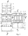
- the covering material 1a hereinafter referred to as a benefit
- a suction station 3 the covering material 1a
- a utility cylinder 4 which detects a benefit 1a with its grippers 4a at a standstill and on a glue roller 5 passes.
- a gripper bar 6 which can be moved forwards and backwards in a straight line takes over the glued panel 1a at a standstill from the panel cylinder 4 and places it on a table 7.
- a transport arm 14 which is rotatable about a vertical axis 13 and movable up and down in the vertical plane.
- the two blankets 1b are transported by transporters 17 into the preparation area 11, while the back insert 1c is fed from the roll and cut to length by means of a cutting unit 18.
- the transport arm 14 which can be moved between the preparation station 11 and the ceiling table 7 by rotary movement, picks up the provided cardboards 1b and 1c via the suction plate arrangement 15 and feeds them to the ceiling table 7, which is in a takeover position which runs obliquely to the cardboards 1b and 1c. After the rotary movement has ended, the transport arm 14 lowers and the cardboards 1b and 1c held by the suction plate arrangement 15 are first brought into contact with the panel 1a on the head-turning side.
- a wrapping station with wrapping elements arranged in vertically offset planes for executing the head and foot impacts in a first level and for carrying out the side wraps in a second level.
- the functions of joining the blanket 1 a and blankets 1b, head and foot wrap and side wrap are coordinated with one another in such a way that all functions take place simultaneously on different book covers, so that a machine cycle is available for every process including the transport movement.
- a transport device in the form of a suction bar 22 with suction pads 23 distributed thereon over the length of the blanket detects the blanket 1 assembled from the cardboards 1b, 1c and panels 1a on one side over its entire side length in order to feed it stretched to the wrapping station.
- the blanket 1 is underpinned on the side opposite the suction cups 23 by a support rail 24 which can be steered into the movement path and back.
- the suction bar 22 with the suction cups 23 is located on a carriage 25 with rollers 26 engaging on a guide track 27 and is moved back and forth by a drive system 28.
- suction rails 29 take over the ceiling 1 in the areas near the side in the feed plane.
- the suction rails 29 can be moved vertically via vertical guide rods 30 in the direction of the arrow and can thus press the ceiling 1 against pressure rails 31 after the support rail 24 has been moved back by a slight downward stroke.
- the pressure rails 31 can also remain below the impact rail 35 and the suction rails 29 take over the vertical transport.
- the downward movement takes place in a position in which the upper edge of the cover paper 1b and 1c is below the wrapping rails 35.
- the impact rails 35 move inward in the direction of the arrow, the suction rails 29 lift off and the pressure rails 31 press the ceiling to achieve a tight impact against the impact rails 35, which are still moving inwards.
- the corners are drawn in via corner retraction elements 33 which are guided by the impact rails 35.
- the pressure rails 31 detach themselves from the ceiling and move outward in the direction of the arrow in order to clear the way for the ceiling 1 for a further downward movement into the side wrapping station located below.
- the ceiling 1 is taken over in the plane of the head and foot folds by height-movable first sections 36a of suction strips arranged in parallel and distributed over the length of the ceiling, which initially move the ceiling 1 to an intermediate level, in which second height-adjustable sections 36b take over the ceiling 1. to lower them together with the first sections 36a to the level in which the side folds are carried out.
- the lateral projections of the ceiling 1 are erected on erection rails 37.
- the flipping of the side turns takes place in a known manner by driving in side turning rails 38 while exerting a contact pressure by the suction strips 36a, 36b.
- the suction strips 36a, 36b lower and place the blanket 1 on a transport system 39, 40 for the removal of the blanket 1 by transporters 39 of an export chain 40 into a downstream pressure roller pair 41 and on an adjoining export belt 42.
- cover cardboard 1b is placed on a cardboard pre-stacking belt 50 and automatically placed in a cardboard magazine 51, in which the front edge, formed by stops 52 with a passage strip function, is adjustable.
- the cardboard magazine 51 the cardboards 1b are separated by a short-stroke slide 53 and in front of transporters 54 placed on the side toothed belt 55.
- the slide 53 runs slightly obliquely downwards.
- the return stroke takes place immediately, which means that the stack is relieved.
- the engagement height of the transporters 54 is adjusted by height settings of guide rails, not shown.
- the toothed belts run continuously at cycle speed and transfer the cardboards 1b synchronously to a blanket cylinder 56 with an upper roller 57.
- the stops 52 are adjusted Extraction device coming to length and fed.
- the coverings 1a are fed, again referred to below as the benefit, namely by circumferential gripper bars 60 of a chain system 61 directly to the benefit cylinder 56.
- B. in the form of a scale from a pre-stacking belt 62 in a utility magazine 63, from which they are tipped down by a squeegee 64 and transferred to the gripper bar 60 by a synchronous movement of the squeegee 64 in the transport direction. Blown air can be used to loosen the pile of useful items in order to avoid rolling effects.
- the feed control of the panels 1a present in scale formation is carried out via light sensors 65.
- the book covers are kept at a height via support strips (not shown) so that upper suction devices 70 can take over the book cover while the chain system 69 is at a standstill.
- the suction devices 70 bring the book cover into the head and foot wrap plane and place it on extended pressure rails 71.
- the head and foot impacts are erected on stationary erection rails 73.
- Wrapping rails 72 then perform the head and foot impact while the suction cups 70 return to their starting position upwards. With the head and foot impact, the corner is folded over known corner retraction elements.
- lower suction devices 74 move under the book covers, to take them over after the wrapping has ended and to transport them downward into the side wrap plane after the pressure rails 71 and wrapping rails 72 have been retracted.
- the book cover is placed on side suction rails 75, which are advanced at this time and hold the book cover with suction cups.
- the side impact is now effected via the impact rail 76, in that the impact is erected by a vertical movement and rubbed by a subsequent horizontal movement.
- the suckers 74 move out of the format area in the direction of the head and foot of the book cover, so that after the suction rails 75 and wrapping rails 76 have been pulled back, the book cover can fall onto the execution level.
- the lower suction cups 74 now run with an oblique movement upwards into the takeover position of the head and foot impact plane. In this case, deflectors on the suckers 74 inevitably accelerate the finished book cover downward, so that the transport to the execution level is not dependent on free fall.
- the book cover falls on a support table 78 and is pushed there by a conveyor chain 79 running constantly at cycle speed into the rolling station 80.
- the lower suction cups 74 perform a movement in the direction of the arrow, for which purpose they can be moved vertically linearly and pivoted horizontally via drives 81. According to the invention, in this exemplary embodiment of a book cover machine all functions are carried out simultaneously on different book covers within one cycle or that all operations are carried out in successive cycles on a book cover.
Landscapes
- Engineering & Computer Science (AREA)
- Manufacturing & Machinery (AREA)
- Mechanical Engineering (AREA)
- Making Paper Articles (AREA)
- Folding Of Thin Sheet-Like Materials, Special Discharging Devices, And Others (AREA)
Applications Claiming Priority (4)
| Application Number | Priority Date | Filing Date | Title |
|---|---|---|---|
| DE4241387 | 1992-12-09 | ||
| DE4241387 | 1992-12-09 | ||
| DE4308469 | 1993-03-17 | ||
| DE4308469A DE4308469A1 (de) | 1992-12-09 | 1993-03-17 | Buchdeckenmaschine |
Publications (2)
| Publication Number | Publication Date |
|---|---|
| EP0603501A1 true EP0603501A1 (fr) | 1994-06-29 |
| EP0603501B1 EP0603501B1 (fr) | 1997-03-19 |
Family
ID=25921121
Family Applications (1)
| Application Number | Title | Priority Date | Filing Date |
|---|---|---|---|
| EP93117531A Expired - Lifetime EP0603501B1 (fr) | 1992-12-09 | 1993-10-29 | Machine à fabriquer des couvertures de livres |
Country Status (3)
| Country | Link |
|---|---|
| US (1) | US5413446A (fr) |
| EP (1) | EP0603501B1 (fr) |
| JP (1) | JPH06210981A (fr) |
Cited By (1)
| Publication number | Priority date | Publication date | Assignee | Title |
|---|---|---|---|---|
| DE102011003348A1 (de) * | 2011-01-28 | 2012-08-02 | Maping Kommandiittiyhtiö L. Huotari | Gerät zur Herstellung von Buchdeckeln und Verfahren zur Verwendung des Gerätes zur Herstellung von Buchdeckeln |
Families Citing this family (21)
| Publication number | Priority date | Publication date | Assignee | Title |
|---|---|---|---|---|
| US6302388B1 (en) | 1995-11-22 | 2001-10-16 | Quad/Graphics, Inc. | Apparatus and method for securing an item to a cover of printed material |
| US5988620A (en) * | 1995-11-22 | 1999-11-23 | Quad/Tech, Inc. | Apparatus and method for personalizing printed materials |
| US5634633A (en) * | 1995-11-22 | 1997-06-03 | Quad/Tech, Inc. | Apparatus and method for securing an item to printed material |
| US5827033A (en) * | 1996-06-06 | 1998-10-27 | James D. Welch | Case making dies and systems, and methods of adjustment, alignment and use thereof |
| US6494661B1 (en) * | 2000-05-12 | 2002-12-17 | Heidelberger Druckmaschinen Ag | Device and method for providing a cover for a book |
| FI107597B (fi) * | 2000-05-19 | 2001-09-14 | Maping Ky L Huotari | Menetelmä ja laite kirjan tms. kansien valmistamiseksi |
| US6379094B1 (en) | 2000-05-24 | 2002-04-30 | Thomas Porat | Apparatus for tucking hard book covers |
| DE10057599C5 (de) * | 2000-11-21 | 2015-02-19 | Kolbus Gmbh & Co. Kg | Vorrichtung zum Herstellen von Bucheinbanddecken |
| DE10057600B4 (de) * | 2000-11-21 | 2008-10-09 | Kolbus Gmbh & Co. Kg | Vorrichtung zum Zuführen von Rückeneinlagen für das maschinelle Herstellen von Bucheinbanddecken |
| AU2003272395A1 (en) * | 2002-09-13 | 2004-04-30 | Gp2 Technologies, Inc. | Apparatus and method for manufacturing hard book cover assemblies |
| DE102005051477A1 (de) * | 2005-10-24 | 2007-04-26 | Michael Hörauf Maschinenfabrik GmbH & Co. KG | Verfahren und Vorrichtung zum Beziehen eines flach liegenden Zuschnittes mit einem Bezug |
| FI117825B (fi) * | 2006-01-25 | 2007-03-15 | Maping Ky L Huotari | Menetelmä ja laite kirjan kannen viimeistelyyn |
| DE102007018023A1 (de) * | 2007-04-17 | 2008-10-23 | Peter Schmidkonz | Verfahren und Einrichtung zum maschinellen Herstellen von Buchdecken für Einzelbücher und Kleinstauflagen unterschiedlicher Formatgrößen |
| US8123449B2 (en) * | 2007-11-05 | 2012-02-28 | Gp2 Technologies, Inc. | Single axis apparatus for manufacturing hard book cover |
| DE102007057228A1 (de) * | 2007-11-28 | 2009-06-04 | Kolbus Gmbh & Co. Kg | Vorrichtung zum Überführen einer Buchdecke von einer Anrolleinrichtung zu einer Übergabestelle |
| JP5208574B2 (ja) * | 2008-05-14 | 2013-06-12 | ホリゾン・インターナショナル株式会社 | 表紙折り曲げ装置 |
| DE102010024232B4 (de) * | 2010-06-18 | 2024-11-07 | Kolbus Gmbh & Co. Kg | Verfahren und Vorrichtung zur Herstellung von Buchdecken |
| ITMI20111016A1 (it) * | 2011-06-06 | 2012-12-07 | Sitma Machinery S P A | Gruppo e metodo per la realizzazione in continuo di sovracopertine di varie dimensioni a partire da una pellicola avvolta in bobina |
| ITTO20120175A1 (it) * | 2012-02-27 | 2013-08-28 | Smyth S R L | Metodo e macchina per la realizzazione di copertine rigide per libri |
| CN114599523B (zh) * | 2019-09-10 | 2023-05-09 | 深圳市高登设备有限公司 | 一种全自动书籍勒口装置 |
| US11787218B1 (en) * | 2023-02-14 | 2023-10-17 | Lightning Source LLC | Book cover embossing system and method |
Citations (1)
| Publication number | Priority date | Publication date | Assignee | Title |
|---|---|---|---|---|
| DE1436088A1 (de) * | 1963-06-22 | 1968-10-24 | Smyth Europea Spa | Maschine zur Herstellung von Bucheinbaenden |
Family Cites Families (3)
| Publication number | Priority date | Publication date | Assignee | Title |
|---|---|---|---|---|
| US2501733A (en) * | 1948-12-03 | 1950-03-28 | Herman A Merz | Case turning-in machine |
| US2556787A (en) * | 1949-02-12 | 1951-06-12 | Florez Company Inc De | Register control for web fed casemaking machines |
| DE3817993C2 (de) * | 1987-07-10 | 1999-06-17 | Kolbus Gmbh & Co Kg | Einschlagvorrichtung für eine Maschine zum Herstellen von Bucheinbanddecken |
-
1993
- 1993-10-29 EP EP93117531A patent/EP0603501B1/fr not_active Expired - Lifetime
- 1993-12-03 US US08/162,536 patent/US5413446A/en not_active Expired - Lifetime
- 1993-12-08 JP JP5308102A patent/JPH06210981A/ja not_active Ceased
Patent Citations (1)
| Publication number | Priority date | Publication date | Assignee | Title |
|---|---|---|---|---|
| DE1436088A1 (de) * | 1963-06-22 | 1968-10-24 | Smyth Europea Spa | Maschine zur Herstellung von Bucheinbaenden |
Non-Patent Citations (2)
| Title |
|---|
| E. BENDIG ET AL.: "Lehrbuch der industriellen Buchbinderei", 1990, VERLAG BERUF + SCHULE, ITZEHOE, DE * |
| G.M.L. WORTEL ET AL.: "Brocheren en uitgaafbinden", 1991, GOC-UITGEVERIJ / GAADE UITGEVERS, AMSTERDAM / HOUTEN * |
Cited By (1)
| Publication number | Priority date | Publication date | Assignee | Title |
|---|---|---|---|---|
| DE102011003348A1 (de) * | 2011-01-28 | 2012-08-02 | Maping Kommandiittiyhtiö L. Huotari | Gerät zur Herstellung von Buchdeckeln und Verfahren zur Verwendung des Gerätes zur Herstellung von Buchdeckeln |
Also Published As
| Publication number | Publication date |
|---|---|
| EP0603501B1 (fr) | 1997-03-19 |
| JPH06210981A (ja) | 1994-08-02 |
| US5413446A (en) | 1995-05-09 |
Similar Documents
| Publication | Publication Date | Title |
|---|---|---|
| EP0603501B1 (fr) | Machine à fabriquer des couvertures de livres | |
| DE3429761C2 (fr) | ||
| EP0187344B1 (fr) | Procédé et dispositif pour produire des piles individuelles composées d'une bande en accordéon | |
| EP0386524B1 (fr) | Dispositif d'emballage d'objets de différentes dimensions | |
| DE69605185T2 (de) | Verpackungsmaschine für mehrstück-verpakungen | |
| EP0117974B1 (fr) | Procédé et dispositif pour la fabrication d'emballages collectifs | |
| DE69322406T2 (de) | Transfersystem zur mehrfachfaltung | |
| DE3937995C2 (de) | Verfahren und Vorrichtung zur Bogenriesvereinzelung und zur Riesablage | |
| DE3813729A1 (de) | Stapeln von buendeln flachgefalteter schachteln aus wellpappe | |
| DD144393A5 (de) | Stapelvorrichtung fuer faltschachteln | |
| DE2151466A1 (de) | Vorrichtung zum Bearbeiten von Bogen | |
| DE3321756A1 (de) | Vorrichtung zum stapeln von zuschnitten | |
| DE19839924A1 (de) | Vorrichtung zur Abnahme von Folien von einem Folienstapel in einer Stapelstation und zur Ablage der abgenommenen Folien in einer Zusammenlegestation | |
| CH686620A5 (de) | Verfahren und Anordnung zum Herstellen von Buchern oder Broschuren. | |
| DE10057599A1 (de) | Vorrichtung zum Herstellen von Bucheinbanddecken | |
| DE3447331A1 (de) | Pneumatischer bogenanleger | |
| DE10057602A1 (de) | Vorrichtung zum Herstellen von Bucheinbanddecken | |
| DE3911969A1 (de) | Vorrichtung zum riesweisen ablegen von boegen, insbesondere papierboegen, auf einen stapel | |
| EP0243944A1 (fr) | Dispositif pour fabriquer des paquets ou des piles de feuilles de papier pliées | |
| DE1461826A1 (de) | Paketformmaschine | |
| DE2618950A1 (de) | Plattentransportmaschine | |
| DE4308469A1 (de) | Buchdeckenmaschine | |
| EP0603502B1 (fr) | Machine à fabriquer des couvertures de livres | |
| DE2741332A1 (de) | Verfahren zur herstellung eines buchblocks sowie vorrichtung zur durchfuehrung des verfahrens | |
| DE4209141C2 (de) | Vorrichtung zur Herstellung von Verpackungen, insbesondere Kartons, aus flachen Zuschnitten |
Legal Events
| Date | Code | Title | Description |
|---|---|---|---|
| PUAI | Public reference made under article 153(3) epc to a published international application that has entered the european phase |
Free format text: ORIGINAL CODE: 0009012 |
|
| AK | Designated contracting states |
Kind code of ref document: A1 Designated state(s): CH DE FR GB IT LI |
|
| 17P | Request for examination filed |
Effective date: 19940719 |
|
| GRAG | Despatch of communication of intention to grant |
Free format text: ORIGINAL CODE: EPIDOS AGRA |
|
| GRAH | Despatch of communication of intention to grant a patent |
Free format text: ORIGINAL CODE: EPIDOS IGRA |
|
| GRAH | Despatch of communication of intention to grant a patent |
Free format text: ORIGINAL CODE: EPIDOS IGRA |
|
| 17Q | First examination report despatched |
Effective date: 19960219 |
|
| GRAA | (expected) grant |
Free format text: ORIGINAL CODE: 0009210 |
|
| AK | Designated contracting states |
Kind code of ref document: B1 Designated state(s): CH DE FR GB IT LI |
|
| REG | Reference to a national code |
Ref country code: CH Ref legal event code: EP |
|
| ET | Fr: translation filed | ||
| REF | Corresponds to: |
Ref document number: 59305868 Country of ref document: DE Date of ref document: 19970424 |
|
| GBT | Gb: translation of ep patent filed (gb section 77(6)(a)/1977) |
Effective date: 19970415 |
|
| ITF | It: translation for a ep patent filed | ||
| PLBE | No opposition filed within time limit |
Free format text: ORIGINAL CODE: 0009261 |
|
| STAA | Information on the status of an ep patent application or granted ep patent |
Free format text: STATUS: NO OPPOSITION FILED WITHIN TIME LIMIT |
|
| 26N | No opposition filed | ||
| REG | Reference to a national code |
Ref country code: CH Ref legal event code: NV Representative=s name: A. BRAUN, BRAUN, HERITIER, ESCHMANN AG PATENTANWAE |
|
| PGFP | Annual fee paid to national office [announced via postgrant information from national office to epo] |
Ref country code: FR Payment date: 20010718 Year of fee payment: 9 |
|
| PGFP | Annual fee paid to national office [announced via postgrant information from national office to epo] |
Ref country code: GB Payment date: 20011031 Year of fee payment: 9 |
|
| REG | Reference to a national code |
Ref country code: GB Ref legal event code: IF02 |
|
| PG25 | Lapsed in a contracting state [announced via postgrant information from national office to epo] |
Ref country code: GB Free format text: LAPSE BECAUSE OF NON-PAYMENT OF DUE FEES Effective date: 20021029 |
|
| GBPC | Gb: european patent ceased through non-payment of renewal fee | ||
| PG25 | Lapsed in a contracting state [announced via postgrant information from national office to epo] |
Ref country code: FR Free format text: LAPSE BECAUSE OF NON-PAYMENT OF DUE FEES Effective date: 20030630 |
|
| REG | Reference to a national code |
Ref country code: FR Ref legal event code: ST |
|
| PG25 | Lapsed in a contracting state [announced via postgrant information from national office to epo] |
Ref country code: IT Free format text: LAPSE BECAUSE OF NON-PAYMENT OF DUE FEES;WARNING: LAPSES OF ITALIAN PATENTS WITH EFFECTIVE DATE BEFORE 2007 MAY HAVE OCCURRED AT ANY TIME BEFORE 2007. THE CORRECT EFFECTIVE DATE MAY BE DIFFERENT FROM THE ONE RECORDED. Effective date: 20051029 |
|
| PGFP | Annual fee paid to national office [announced via postgrant information from national office to epo] |
Ref country code: DE Payment date: 20071004 Year of fee payment: 15 |
|
| PGFP | Annual fee paid to national office [announced via postgrant information from national office to epo] |
Ref country code: CH Payment date: 20071024 Year of fee payment: 15 |
|
| REG | Reference to a national code |
Ref country code: CH Ref legal event code: PFA Owner name: KOLBUS GMBH & CO. KG Free format text: KOLBUS GMBH & CO. KG#OSNABRUECKER STRASSE 77#D-32369 RAHDEN (DE) -TRANSFER TO- KOLBUS GMBH & CO. KG#OSNABRUECKER STRASSE 77#D-32369 RAHDEN (DE) |
|
| REG | Reference to a national code |
Ref country code: CH Ref legal event code: PL |
|
| PG25 | Lapsed in a contracting state [announced via postgrant information from national office to epo] |
Ref country code: DE Free format text: LAPSE BECAUSE OF NON-PAYMENT OF DUE FEES Effective date: 20090501 |
|
| PG25 | Lapsed in a contracting state [announced via postgrant information from national office to epo] |
Ref country code: LI Free format text: LAPSE BECAUSE OF NON-PAYMENT OF DUE FEES Effective date: 20081031 Ref country code: CH Free format text: LAPSE BECAUSE OF NON-PAYMENT OF DUE FEES Effective date: 20081031 |