EP0603543A1 - Méthode et dispositif de surveillance d'un dispositif de commande dans un moteur à combustion - Google Patents
Méthode et dispositif de surveillance d'un dispositif de commande dans un moteur à combustion Download PDFInfo
- Publication number
- EP0603543A1 EP0603543A1 EP93118541A EP93118541A EP0603543A1 EP 0603543 A1 EP0603543 A1 EP 0603543A1 EP 93118541 A EP93118541 A EP 93118541A EP 93118541 A EP93118541 A EP 93118541A EP 0603543 A1 EP0603543 A1 EP 0603543A1
- Authority
- EP
- European Patent Office
- Prior art keywords
- signal
- value
- output signal
- lambda probe
- expected
- Prior art date
- Legal status (The legal status is an assumption and is not a legal conclusion. Google has not performed a legal analysis and makes no representation as to the accuracy of the status listed.)
- Granted
Links
- 238000000034 method Methods 0.000 title claims abstract description 27
- 238000002485 combustion reaction Methods 0.000 title claims abstract description 19
- 238000012544 monitoring process Methods 0.000 claims abstract description 7
- 239000000523 sample Substances 0.000 claims description 48
- 238000001514 detection method Methods 0.000 claims description 38
- 239000000446 fuel Substances 0.000 claims description 7
- 239000007789 gas Substances 0.000 description 31
- 230000006870 function Effects 0.000 description 20
- 238000010438 heat treatment Methods 0.000 description 8
- 239000007858 starting material Substances 0.000 description 6
- QVGXLLKOCUKJST-UHFFFAOYSA-N atomic oxygen Chemical compound [O] QVGXLLKOCUKJST-UHFFFAOYSA-N 0.000 description 5
- 239000001301 oxygen Substances 0.000 description 5
- 229910052760 oxygen Inorganic materials 0.000 description 5
- 238000012806 monitoring device Methods 0.000 description 4
- 230000007547 defect Effects 0.000 description 3
- 238000002347 injection Methods 0.000 description 3
- 239000007924 injection Substances 0.000 description 3
- 230000001276 controlling effect Effects 0.000 description 2
- 238000010586 diagram Methods 0.000 description 2
- 230000001105 regulatory effect Effects 0.000 description 2
- 238000013459 approach Methods 0.000 description 1
- 238000007664 blowing Methods 0.000 description 1
- 238000004364 calculation method Methods 0.000 description 1
- 238000007796 conventional method Methods 0.000 description 1
- 230000002950 deficient Effects 0.000 description 1
- 238000009795 derivation Methods 0.000 description 1
- 238000011161 development Methods 0.000 description 1
- 230000018109 developmental process Effects 0.000 description 1
- 238000003745 diagnosis Methods 0.000 description 1
- 230000000694 effects Effects 0.000 description 1
- 239000000203 mixture Substances 0.000 description 1
- 230000002123 temporal effect Effects 0.000 description 1
- 238000012360 testing method Methods 0.000 description 1
Images
Classifications
-
- F—MECHANICAL ENGINEERING; LIGHTING; HEATING; WEAPONS; BLASTING
- F02—COMBUSTION ENGINES; HOT-GAS OR COMBUSTION-PRODUCT ENGINE PLANTS
- F02D—CONTROLLING COMBUSTION ENGINES
- F02D41/00—Electrical control of supply of combustible mixture or its constituents
- F02D41/02—Circuit arrangements for generating control signals
- F02D41/14—Introducing closed-loop corrections
- F02D41/1438—Introducing closed-loop corrections using means for determining characteristics of the combustion gases; Sensors therefor
- F02D41/1493—Details
- F02D41/1495—Detection of abnormalities in the air/fuel ratio feedback system
-
- F—MECHANICAL ENGINEERING; LIGHTING; HEATING; WEAPONS; BLASTING
- F02—COMBUSTION ENGINES; HOT-GAS OR COMBUSTION-PRODUCT ENGINE PLANTS
- F02D—CONTROLLING COMBUSTION ENGINES
- F02D41/00—Electrical control of supply of combustible mixture or its constituents
- F02D41/22—Safety or indicating devices for abnormal conditions
- F02D41/222—Safety or indicating devices for abnormal conditions relating to the failure of sensors or parameter detection devices
-
- F—MECHANICAL ENGINEERING; LIGHTING; HEATING; WEAPONS; BLASTING
- F02—COMBUSTION ENGINES; HOT-GAS OR COMBUSTION-PRODUCT ENGINE PLANTS
- F02D—CONTROLLING COMBUSTION ENGINES
- F02D41/00—Electrical control of supply of combustible mixture or its constituents
- F02D41/02—Circuit arrangements for generating control signals
- F02D41/14—Introducing closed-loop corrections
- F02D41/1401—Introducing closed-loop corrections characterised by the control or regulation method
- F02D41/1404—Fuzzy logic control
-
- Y—GENERAL TAGGING OF NEW TECHNOLOGICAL DEVELOPMENTS; GENERAL TAGGING OF CROSS-SECTIONAL TECHNOLOGIES SPANNING OVER SEVERAL SECTIONS OF THE IPC; TECHNICAL SUBJECTS COVERED BY FORMER USPC CROSS-REFERENCE ART COLLECTIONS [XRACs] AND DIGESTS
- Y02—TECHNOLOGIES OR APPLICATIONS FOR MITIGATION OR ADAPTATION AGAINST CLIMATE CHANGE
- Y02T—CLIMATE CHANGE MITIGATION TECHNOLOGIES RELATED TO TRANSPORTATION
- Y02T10/00—Road transport of goods or passengers
- Y02T10/10—Internal combustion engine [ICE] based vehicles
- Y02T10/40—Engine management systems
Definitions
- the invention relates to a method and a device for monitoring a control device of an internal combustion engine according to the preambles of the independent claims.
- Such a method and such a device for monitoring a control device of an internal combustion engine is known from DE-OS 28 05 876 (US Pat. No. 4,292,658). There, a method and a device are described in which it is checked whether a manipulated variable for an interlocking exceeds a fixed lower and / or fixed upper limit.
- the invention has for its object to provide a method and a device for monitoring a control device of an internal combustion engine of the type mentioned with which the control device can be monitored during operation to determine whether all elements, in particular the actuators and sensors, are working properly.
- the lambda probe is to be regarded as particularly critical. If the lambda probe is defective, increased exhaust gas emissions result. A defect or fault in the lambda sensor should be recognized before the sensor fails completely.
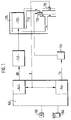
- FIG. 1 shows a roughly schematic system for controlling an internal combustion engine
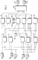
- FIG. 2 shows a monitoring device
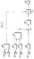
- FIG. 3 shows a monitoring device in detail
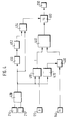
- FIG. 4 shows another monitoring device in detail
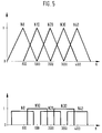
- FIG. 5 shows the membership functions of a fuzzy logic.
- Figure 1 shows a schematic diagram of a system for controlling an internal combustion engine.
- This exemplary embodiment is a diesel internal combustion engine.
- the method and the device can also be used in a spark-ignition internal combustion engine.
- An internal combustion engine 100 receives fresh air via a fresh air line 105.
- the exhaust gas is discharged via an exhaust pipe 110.
- a lambda probe 125 is arranged in the exhaust line 110.
- the exhaust line 110 and the fresh air line 105 are connected via an exhaust gas recirculation valve 138.
- an electronic control unit 140 is provided. This includes, among other things, a quantity control 142 and an exhaust gas recirculation control 144.
- the quantity control 142 applies an injection pump 145 to a signal QK which, depending on this signal QK, measures a defined quantity of fuel in the internal combustion engine.
- the exhaust gas recirculation controller 144 is connected to an electropneumatic converter 150. This electropneumatic converter 150 actuates the exhaust gas recirculation valve 138.
- the lambda probe 125 supplies a signal U to the quantity control 142 and to the exhaust gas recirculation control 144. In a first approximation, this signal is proportional to the oxygen concentration in the exhaust gas.
- the electronic control unit 140 is also connected to various sensors 155 for detecting the speed and 160 for detecting the driver's request QKW.
- the composition of the air supplied to the internal combustion engine can be influenced via the exhaust gas recirculation valve 138.
- the exhaust gas recirculation controller 144 outputs a signal TV with a corresponding pulse duty factor to the electropneumatic converter 150.
- the exhaust gas recirculation valve 138 opens and a large exhaust gas recirculation rate results. Accordingly, a small exhaust gas recirculation rate results with a small duty cycle.
- the injection pump 145 supplies the internal combustion engine 100 with the amount of fuel necessary for the combustion.
- the control signals QK for the injection pump 145 and the pulse duty factor TV for the electropneumatic converter 150 are specified by the electronic control unit 140.
- the electronic control unit 140 evaluates various signals. These are, on the one hand, a speed signal N of the speed sensor 155 and a load signal QKW, which is detected by the sensor 160 in the form of the accelerator pedal position.
- the output signal of the lambda probe 125 reaches both the quantity control 142 and the exhaust gas recirculation control 144.
- the lambda probe 125 is designed such that it delivers an output signal which is proportional to the oxygen concentration in the exhaust gas. This means it defines a defined relationship between the oxygen concentration in the exhaust gas and the output signal U of the lambda sensor.
- a voltage detection means 200 detects the battery voltage U bat .
- Various means are provided that recognize certain operating states.
- a starter identification 210, an idling identification 212, a slip detection 214, a stationary identification 216 and a cold-blowing identification 218 are provided.
- the starter detection 210 evaluates the output signal of the speed sensor 155.
- the idle speed detection 212 is supplied with the speed signal N and the driver's request signal QKW from the accelerator pedal position transmitter 160.
- the thrust detection 214 receives the quantity signal QK of the quantity control 142 and the speed signal N of the speed sensor 155.
- the stationary detection 216 evaluates the duty cycle TV of the exhaust gas recirculation control 144, the speed signal N and the quantity signal QK of the quantity control 142.
- the cold blow detection 218 evaluates the battery voltage U bat , the speed N and the quantity signal QK.
- the start detection 210 applies a start signal to a battery tester 220 and a heating tester 222. Furthermore, the starter detection 210 applies a signal to an exhaust gas recirculation controller tester 224, a probe dynamics tester 226, a probe characteristic tester 228 and a second heating tester 229, which characterizes normal operation outside of the starting situation.
- the idle detection 212 applies a signal to the exhaust gas recirculation controller tester 224. This signal indicates the idle operating state.
- the thrust detection 214 applies a signal to a probe dynamics tester 226. This signal indicates the operating status overrun.
- the stationary detection 216 applies a signal to a probe characteristic tester 228. This signal indicates a steady state.
- the cold blow detection 218 applies a signal to a second heating tester 229.
- a battery tester 220 also processes a signal relating to the battery voltage U bat .
- the output tester U of the lambda probe 125 is also fed to the heating tester 222.
- the exhaust gas recirculation controller tester 224 is also supplied with the output signal TV of the exhaust gas recirculation control 144, a signal MLI with respect to the actual value of the intake air mass and a signal MLS with the setpoint value of the intake air mass.
- the MLI signal with respect to the actual value comes from block 204.
- the MLS signal comes from block 206.
- the probe dynamics tester 226 evaluates the output signal U of the lambda probe 125 and the pulse duty factor TV of the exhaust gas recirculation control 144.
- the probe characteristic tester 228 evaluates the output signal U of the lambda probe 125, the speed signal N and the quantity signal QK of the quantity control 142.
- the second heating tester 229 is also supplied with the output signal U of the lambda probe 125.
- the output signals of the testers 220, 222, 224, 226, 228 and 229 arrive at an error detection.
- This error detection 230 provides two signals.
- the testers are preferably also implemented as fuzzy logic.
- fuzzy logic observers or corresponding characteristic maps or a logic unit can also be provided.
- the characteristic diagrams or the logic units can be implemented with discrete components or as individual program steps of a microcomputer.
- the detections and the testers can also evaluate further signals if corresponding sensors or the corresponding signals are available.
- the starter detection 210 evaluates the speed signal N. If the speed signal is below a predetermined threshold, which is in the range of approx. 800 revolutions per minute, then it emits a signal which identifies the starting process. If this threshold is exceeded, then after a predetermined time of a few seconds it emits a signal which indicates the operation of the internal combustion engine outside of the start.
- a predetermined threshold which is in the range of approx. 800 revolutions per minute
- the idling detection 212 recognizes on the basis of the rotational speed and the driver's request whether the idling operating state is present.
- the idle operating state is present, for example, when the speed is in the range of the idle speed of approximately 800 revolutions per minute and the accelerator pedal is not actuated.
- the stationary detection 216 detects a stationary operating state if the rate of change of the monitored signals does not exceed predetermined limit values. For example, it is checked whether the derivation of the duty cycle TV, the rotational speed N and / or the quantity signal QK exceeds a predefined threshold, or whether these signals change by more than a predefined amount within a specific time interval. If the change in the evaluated signals is below certain threshold values, a stationary operating state is recognized and a corresponding signal is output.
- the detections are preferably implemented as logic units. In the case of stationary detection 216 in particular, it is advantageous if it is implemented as fuzzy logic.
- the battery tester 220 receives a signal from the starter recognition 210 that there is a start, the course of the battery voltage U bat is observed. If the battery voltage deviates from the intended course, the battery tester 220 generates a corresponding error signal.
- the heating tester 222 checks whether the output signal U of the lambda probe 125 corresponds to the expected values or the expected temporal course of the values.
- the exhaust gas recirculation control tester 224 checks whether the controllers and controllers of the exhaust gas recirculation control are working properly. This check is preferably done in idle.
- the lambda probe is usually heated.
- the temperature of the lambda probe is regulated to a specific temperature value.
- the second heating tester 229 checks whether a corresponding output signal U of the lambda probe 125 is present. The correct function of the heating can thus be checked.
- Signal A of error detection 230 merely indicates that there is an error.
- this error signal is assigned to the faulty device.
- the signals A and F are fed to corresponding blocks 232 and 234, which further process these signals. For example, it can be provided that, depending on the signal F, a corresponding indicator light is activated or a memory bit is set, which is evaluated during diagnosis in the context of customer service.
- the signal of the start detection 210 which indicates the operation outside the start, and the output signal of the stationary detection 218 are logically combined in an AND gate 300.
- the output signal of the AND gate 300 arrives at a threshold value query 330.
- the speed signal N reaches an observer 310 via a first signal shaper 302.
- the quantity signal QK also reaches the observer 310 via a second signal shaper 304.
- the output signal U of the lambda probe 125 arrives a third signal shaper 306 to an addition point 315, which links this signal with the output signal of the observer 310.
- This linked signal then reaches the threshold value query 330 via an absolute value generator 320.
- the output signal of the tester is then available at the output of this threshold value query. This then arrives at error detection 230.
- the signal formers 302, 304 and 306 are preferably implemented as PT1 elements.
- the observer 310 determines an expected value UE for the output signal of the lambda probe 125. This expected value UE is compared with the measured value U at the addition point 315. On the basis of this comparison result, the absolute value determiner 320 calculates the absolute value X. This absolute value is then compared with a threshold value K in the threshold value query. If the absolute amount of the deviation between the expected and the detected value for the lambda probe signal is greater than the threshold value K, the threshold value query sends a corresponding error signal to the error detection 230.
- the threshold value query 330 only carries out the check if there is a corresponding signal from the AND gate 300. This signal is present when the internal combustion engine is in a stationary operating state outside of the start. This means that stationary detection 216 or starter detection 210 deliver a corresponding signal to the AND gate. The check is only carried out outside the start-up process if there are stationary operating states.
- the observer 310 determines an expected value (UE) for the output signal of the lambda probe based on the speed signal (N) and a signal (QK) indicating the injected fuel quantity.
- the threshold value query 330 detects an error if the expected value (UE) for the output signal of the lambda probe deviates from the measured output signal of the lambda probe by more than a threshold value (K).
- FIG. 4 shows the probe dynamics tester 226 as a further example.
- An AND gate 400 combines the output signals of the thrust detection 214 and the start detection 210.
- the output signal of this AND gate 400 arrives at a first threshold value query 410, a first timing element 450 and a second timing element 420.
- the threshold value query 410 also becomes the output signal U fed to the lambda probe 125.
- the output signal of the second timing element 420 arrives at a duty cycle specification 430, at the input of which the duty cycle TV of the exhaust gas recirculation control 144 is applied.
- the output signal of the duty cycle specification 430 and the output signal T of the threshold value detection reaches the observer 440.
- the output signal in turn reaches the error detection 230 via a second threshold value query 460.
- the output signal of the AND gate 400 passes via the first timing element 450 and the inverter 452 to a further AND gate 454 and directly to the further AND gate 454.
- the further AND gate 454 in turn applies a corresponding signal to the threshold value query 460, in that the threshold value is only queried when a corresponding signal is present at the AND gate 454.
- the AND gate 400 recognizes whether there is a coasting operation in normal operation outside of the start.
- the threshold value query 410 determines the time T within which the output signal U of the lambda probe exceeds or falls below a predetermined threshold after the overrun mode has occurred. This time period T is then fed to the observer 440.
- the second timer 24 ensures that the pulse duty factor TV is kept constant for a certain period of time at the time when the overrun mode is detected.
- the output signal that was present at the output of the exhaust gas recirculation control 144 at the beginning of the push signal is present at the output of the duty ratio specification 430 for the specific time period.
- the observer 440 recognizes whether there is a fault. If this signal lies outside a predetermined threshold value TS, an error signal is transmitted to the error detection 230.
- the first timer in connection with the inverter 452 and the AND gate 454 ensures that when the overrun mode is exited, the checking process takes place after a predetermined period of time TM.
- the threshold value query 460 takes place after the time period TM has elapsed after the start of the overrun operation.
- This predetermined time period TM and the specific time period for which the duty cycle specification has a constant value are preferably chosen to be the same.
- the time period TM is selected so that it corresponds to the largest possible time period TS. If there is no measured time T at the input of the observer 440 within this time period TM, an error is recognized.
- This approach is based on the idea that no fuel quantity is injected in overrun mode and therefore the output signal of the lambda probe 125 indicates the maximum possible oxygen content within a certain time. If this output signal, which corresponds to the maximum oxygen content, is not reached within a certain time period TS, an error must be assumed, particularly in the area of the lambda probe.
- the observer compares the expected rise time with the measured time T within which the output signal of the lambda probe 125 has risen above the threshold value. The observer specifies the expected rise time depending on the duty cycle TV of the exhaust gas recirculation control 144.
- the observer 310 or 410 can be implemented as a map by storing the expected value UE for the output signal of the lambda probe 125 as a function of the speed N and the fuel quantity QK. Furthermore, it is possible to implement these observers as a corresponding logic unit. A particularly advantageous embodiment results if the observer is implemented as fuzzy logic.
- the signals to be evaluated are assigned to certain value ranges in the respective fuzzy logic.
- the strength of the assignment of each individual value to a value range to a category is determined by a membership function.
- the membership functions for different categories of speed are plotted in FIG.
- N8 the membership function for the speed 800 revolutions per minute is recorded. This speed corresponds to the idling speed.
- N10 denotes the membership function for the speed 1000 revolutions per minute.
- N20 denotes the membership function for the speed of 2000 revolutions per minute.
- N30 is the membership function for the speed 3000 revolutions per minute.
- N40 denotes the membership function for the speed of 4000 revolutions per minute.
- the membership function for the speed 800 revolutions per minute is recorded with N8. This speed corresponds to the idling speed.
- N10 denotes the membership function for the speed 1000 revolutions per minute.
- N20 denotes the membership function for the speed of 2000 revolutions per minute.
- N30 is the membership function for the speed 3000 revolutions per minute.
- N40 denotes the membership function for the speed of 4000 revolutions per minute.
- the membership functions are standardized and assume values between zero and one.
- the value 0 indicates that there is no membership in the category under consideration, and the value 1 indicates complete membership.
- the triangular function shown in FIG. 5a is usually selected as the course of the function. If, on the other hand, a rectangular function, as shown in FIG. 5b, is selected, the calculation times are considerably shorter.
Landscapes
- Engineering & Computer Science (AREA)
- Chemical & Material Sciences (AREA)
- Combustion & Propulsion (AREA)
- Mechanical Engineering (AREA)
- General Engineering & Computer Science (AREA)
- Combined Controls Of Internal Combustion Engines (AREA)
- Testing Of Engines (AREA)
- Electrical Control Of Air Or Fuel Supplied To Internal-Combustion Engine (AREA)
Applications Claiming Priority (2)
| Application Number | Priority Date | Filing Date | Title |
|---|---|---|---|
| DE4243493 | 1992-12-22 | ||
| DE4243493A DE4243493A1 (de) | 1992-12-22 | 1992-12-22 | Verfahren und Vorrichtung zur Überwachung einer Steuereinrichtung |
Publications (2)
| Publication Number | Publication Date |
|---|---|
| EP0603543A1 true EP0603543A1 (fr) | 1994-06-29 |
| EP0603543B1 EP0603543B1 (fr) | 1998-02-04 |
Family
ID=6476129
Family Applications (1)
| Application Number | Title | Priority Date | Filing Date |
|---|---|---|---|
| EP93118541A Expired - Lifetime EP0603543B1 (fr) | 1992-12-22 | 1993-11-18 | Méthode et dispositif de surveillance d'un dispositif de commande dans un moteur à combustion |
Country Status (3)
| Country | Link |
|---|---|
| EP (1) | EP0603543B1 (fr) |
| JP (1) | JP3665355B2 (fr) |
| DE (2) | DE4243493A1 (fr) |
Cited By (3)
| Publication number | Priority date | Publication date | Assignee | Title |
|---|---|---|---|---|
| EP0778406A3 (fr) * | 1995-12-05 | 1998-04-22 | Toyota Jidosha Kabushiki Kaisha | Dispositif et méthode par la détection d'anomalies d'un détecteur de débit d'air |
| EP2336532A2 (fr) | 2009-12-16 | 2011-06-22 | Robert Bosch GmbH | Procédé de reconnaissance de la capacité de fonctionnement d'une sonde lambda pour des fonctions dans des phases de fonctionnement sélectionnées |
| CN106103955A (zh) * | 2014-03-10 | 2016-11-09 | 日野自动车株式会社 | 发动机系统的异常判定装置 |
Families Citing this family (8)
| Publication number | Priority date | Publication date | Assignee | Title |
|---|---|---|---|---|
| DE4428816B4 (de) * | 1994-08-13 | 2005-06-02 | Deutz Ag | Verfahren zur Einstellung einer Brennkraftmaschine |
| DE19705766C1 (de) * | 1997-02-14 | 1998-08-13 | Siemens Ag | Verfahren und Einrichtung zum Überwachen eines Sensors, der einer Brennkraftmaschine zugeordnet ist |
| DE19941006A1 (de) * | 1999-08-28 | 2001-03-01 | Volkswagen Ag | Funktionsüberwachung eines Luftmassenregelsystems |
| DE10258426B4 (de) * | 2002-12-13 | 2008-08-21 | Siemens Ag | Verfahren und Vorrichtung zum Überwachen einer Steuereinrichtung einer Brennkraftmaschine |
| DE102008042605B4 (de) * | 2008-10-06 | 2019-12-05 | Robert Bosch Gmbh | Verfahren zum Überprüfen der Funktionstüchtigkeit mindestens eines Einspritzventils |
| JP5825663B2 (ja) * | 2011-07-25 | 2015-12-02 | ボッシュ株式会社 | ラムダセンサの極希薄領域応答性診断方法及びコモンレール式燃料噴射制御装置 |
| DE102011083587B4 (de) | 2011-09-28 | 2023-08-10 | Robert Bosch Gmbh | Verfahren und Vorrichtung zur Überwachung wenigstens eines Teiles einer Brennkraftmaschine |
| DE102014211069A1 (de) * | 2014-06-11 | 2015-12-17 | Robert Bosch Gmbh | Verfahren zur Auswertung der Abweichung einer Kennlinie |
Citations (3)
| Publication number | Priority date | Publication date | Assignee | Title |
|---|---|---|---|---|
| WO1990009517A1 (fr) * | 1989-02-18 | 1990-08-23 | Robert Bosch Gmbh | Procede pour verifier l'etat de marche d'une sonde lambda |
| DE4122828A1 (de) * | 1990-07-10 | 1992-01-16 | Mitsubishi Motors Corp | Luft-brennstoff-verhaeltnis-steuersystem |
| DE4235503A1 (de) * | 1991-10-21 | 1993-04-22 | Nissan Motor | Steuersystem fuer luft-/kraftstoffverhaeltnis fuer verbrennungsmotoren |
Family Cites Families (4)
| Publication number | Priority date | Publication date | Assignee | Title |
|---|---|---|---|---|
| US4119631A (en) * | 1974-10-25 | 1978-10-10 | E. Merck, Patentabteilung | Penicillins and their preparation |
| JPS53125528A (en) * | 1977-04-08 | 1978-11-01 | Nissan Motor Co Ltd | Inspection unit for air fuel ratio controller |
| JP2581828B2 (ja) * | 1990-06-01 | 1997-02-12 | 株式会社日立製作所 | 内燃機関の空燃比制御方法及びその制御装置 |
| JP2503742B2 (ja) * | 1990-08-04 | 1996-06-05 | 三菱電機株式会社 | 内燃機関燃料制御システム |
-
1992
- 1992-12-22 DE DE4243493A patent/DE4243493A1/de not_active Withdrawn
-
1993
- 1993-11-18 EP EP93118541A patent/EP0603543B1/fr not_active Expired - Lifetime
- 1993-11-18 DE DE59308112T patent/DE59308112D1/de not_active Expired - Lifetime
- 1993-12-20 JP JP31929793A patent/JP3665355B2/ja not_active Expired - Lifetime
Patent Citations (3)
| Publication number | Priority date | Publication date | Assignee | Title |
|---|---|---|---|---|
| WO1990009517A1 (fr) * | 1989-02-18 | 1990-08-23 | Robert Bosch Gmbh | Procede pour verifier l'etat de marche d'une sonde lambda |
| DE4122828A1 (de) * | 1990-07-10 | 1992-01-16 | Mitsubishi Motors Corp | Luft-brennstoff-verhaeltnis-steuersystem |
| DE4235503A1 (de) * | 1991-10-21 | 1993-04-22 | Nissan Motor | Steuersystem fuer luft-/kraftstoffverhaeltnis fuer verbrennungsmotoren |
Non-Patent Citations (1)
| Title |
|---|
| TOKUTA INOUE ET.AL.: "FUTURE ENGINE CONTROL", VEHICLE ELECTRONICS IN THE 90'S :PROCEEDINGS OF THE INTERNATIONAL CONGRESS ON TRANSPORTATION ELECTRONICS., vol. P-233, October 1990 (1990-10-01), S.A.E.901152. WARRENDALE,PA, pages 285 - 298, XP000223550 * |
Cited By (8)
| Publication number | Priority date | Publication date | Assignee | Title |
|---|---|---|---|---|
| EP0778406A3 (fr) * | 1995-12-05 | 1998-04-22 | Toyota Jidosha Kabushiki Kaisha | Dispositif et méthode par la détection d'anomalies d'un détecteur de débit d'air |
| EP2336532A2 (fr) | 2009-12-16 | 2011-06-22 | Robert Bosch GmbH | Procédé de reconnaissance de la capacité de fonctionnement d'une sonde lambda pour des fonctions dans des phases de fonctionnement sélectionnées |
| DE102009054751A1 (de) | 2009-12-16 | 2011-06-22 | Robert Bosch GmbH, 70469 | Verfahren zur Erkennung der Betriebsbereitschaft einer Lambda-Sonde für Funktionen in ausgewählten Betriebsphasen |
| DE102009054751B4 (de) | 2009-12-16 | 2022-03-03 | Robert Bosch Gmbh | Verfahren zur Erkennung der Betriebsbereitschaft einer Lambda-Sonde für Funktionen in ausgewählten Betriebsphasen |
| CN106103955A (zh) * | 2014-03-10 | 2016-11-09 | 日野自动车株式会社 | 发动机系统的异常判定装置 |
| EP3118441A4 (fr) * | 2014-03-10 | 2017-10-18 | Hino Motors, Ltd. | Dispositif pour déterminer une anomalie dans un système de moteur |
| US10054074B2 (en) | 2014-03-10 | 2018-08-21 | Hino Motors, Ltd. | Device for determining abnormality in engine system |
| CN106103955B (zh) * | 2014-03-10 | 2019-08-23 | 日野自动车株式会社 | 发动机系统的异常判定装置 |
Also Published As
| Publication number | Publication date |
|---|---|
| EP0603543B1 (fr) | 1998-02-04 |
| JP3665355B2 (ja) | 2005-06-29 |
| DE59308112D1 (de) | 1998-03-12 |
| JPH06212994A (ja) | 1994-08-02 |
| DE4243493A1 (de) | 1994-06-23 |
Similar Documents
| Publication | Publication Date | Title |
|---|---|---|
| EP1327138B1 (fr) | Procede et dispositif d'autodiagnostic d'un capteur de nox | |
| EP0795077B1 (fr) | Procede et dispositif permettant de surveiller un systeme de dosage de carburant | |
| DE3923757A1 (de) | Kraftstoffregler fuer brennkraftmaschinen | |
| DE19733107C2 (de) | Verfahren zur Überprüfung der Funktionsfähigkeit einer Lambdasonde | |
| EP1305514B1 (fr) | Procede d'analyse de la capacite de fonctionnement d'une soupape de recyclage des gaz d'echappement d'un moteur thermique | |
| DE10340844B4 (de) | Vorrichtung und Verfahren zur Fehlerbestimmung bei einem Luftströmungssensor | |
| EP0603543B1 (fr) | Méthode et dispositif de surveillance d'un dispositif de commande dans un moteur à combustion | |
| WO2003004849A1 (fr) | Procede et dispositif pour la surveillance d'un capteur de pression | |
| DE4229774A1 (de) | Vorrichtung zur Steuerung einer Brennkraftmaschine | |
| WO1991003636A1 (fr) | Procede et dispositif pour la verification de la capacite de fonctionnement du chauffage d'une sonde de gaz d'echappement et son systeme d'alimentation | |
| DE4309854C2 (de) | Verfahren und Vorrichtung zur Steuerung der Sekundärluftzufuhr für eine Brennkraftmaschine | |
| DE102006007698B4 (de) | Verfahren zum Betreiben einer Brennkraftmaschine, Computerprogramm-Produkt, Computerprogramm und Steuer- und/oder Regeleinrichtung für eine Brennkraftmaschine | |
| WO1991002147A1 (fr) | Procede et dispositif de commande et/ou de regulation de la puissance du moteur a combustion interne d'un vehicule | |
| DE69705150T2 (de) | Verfahren zur Diagnose des Wirkungsgrades eines stromabwärts von einem Katalysator angeordneten Stochiometrischen Abgassensors | |
| DE19536577A1 (de) | Verfahren zum Überprüfen der Funktionsfähigkeit einer Abgassonden-Heizeinrichtung | |
| EP1309783A1 (fr) | Procede pour commander un moteur a combustion interne | |
| EP1926900B1 (fr) | Procede et dispositif de surveillance d'un systeme de dosage de carburant | |
| DE3927050A1 (de) | Regeleinrichtung fuer brennkraftmaschinen | |
| DE19537381B4 (de) | Verfahren und Vorrichtung zur Steuerung einer Brennkraftmaschine | |
| DE4344633B4 (de) | Lasterfassung mit Diagnose bei einer Brennkraftmaschine | |
| DE102007057311B3 (de) | Verfahren und Vorrichtung zur Fehlererkennung bei emissionsrelevanten Steuereinrichtungen in einem Fahrzeug | |
| DE102006008493B4 (de) | Verfahren und Vorrichtung zur Steuerung einer Brennkraftmaschine | |
| DE112019003496T5 (de) | Steuerungsvorrichtung und Diagnoseverfahren für einen Verbrennungsmotor | |
| EP0708233A2 (fr) | Procédé et dispositif pour commander un moteur à combustion interne | |
| DE10022533B4 (de) | Ausfallsicherungsvorrichtung und Ausfallsicherungsverfahren eines Motors |
Legal Events
| Date | Code | Title | Description |
|---|---|---|---|
| PUAI | Public reference made under article 153(3) epc to a published international application that has entered the european phase |
Free format text: ORIGINAL CODE: 0009012 |
|
| AK | Designated contracting states |
Kind code of ref document: A1 Designated state(s): DE FR GB IT |
|
| 17P | Request for examination filed |
Effective date: 19941229 |
|
| 17Q | First examination report despatched |
Effective date: 19960319 |
|
| GRAG | Despatch of communication of intention to grant |
Free format text: ORIGINAL CODE: EPIDOS AGRA |
|
| GRAH | Despatch of communication of intention to grant a patent |
Free format text: ORIGINAL CODE: EPIDOS IGRA |
|
| GRAH | Despatch of communication of intention to grant a patent |
Free format text: ORIGINAL CODE: EPIDOS IGRA |
|
| GRAA | (expected) grant |
Free format text: ORIGINAL CODE: 0009210 |
|
| AK | Designated contracting states |
Kind code of ref document: B1 Designated state(s): DE FR GB IT |
|
| ET | Fr: translation filed | ||
| REF | Corresponds to: |
Ref document number: 59308112 Country of ref document: DE Date of ref document: 19980312 |
|
| ITF | It: translation for a ep patent filed | ||
| GBT | Gb: translation of ep patent filed (gb section 77(6)(a)/1977) |
Effective date: 19980409 |
|
| PLBE | No opposition filed within time limit |
Free format text: ORIGINAL CODE: 0009261 |
|
| STAA | Information on the status of an ep patent application or granted ep patent |
Free format text: STATUS: NO OPPOSITION FILED WITHIN TIME LIMIT |
|
| 26N | No opposition filed | ||
| REG | Reference to a national code |
Ref country code: GB Ref legal event code: IF02 |
|
| PGFP | Annual fee paid to national office [announced via postgrant information from national office to epo] |
Ref country code: GB Payment date: 20121122 Year of fee payment: 20 Ref country code: IT Payment date: 20121124 Year of fee payment: 20 |
|
| PGFP | Annual fee paid to national office [announced via postgrant information from national office to epo] |
Ref country code: FR Payment date: 20121217 Year of fee payment: 20 |
|
| PGFP | Annual fee paid to national office [announced via postgrant information from national office to epo] |
Ref country code: DE Payment date: 20130124 Year of fee payment: 20 |
|
| REG | Reference to a national code |
Ref country code: DE Ref legal event code: R071 Ref document number: 59308112 Country of ref document: DE |
|
| REG | Reference to a national code |
Ref country code: GB Ref legal event code: PE20 Expiry date: 20131117 |
|
| PG25 | Lapsed in a contracting state [announced via postgrant information from national office to epo] |
Ref country code: GB Free format text: LAPSE BECAUSE OF EXPIRATION OF PROTECTION Effective date: 20131117 Ref country code: DE Free format text: LAPSE BECAUSE OF EXPIRATION OF PROTECTION Effective date: 20131119 |