EP0603560B1 - Système de commande modulaire comprenant une sous-unité intelligente - Google Patents
Système de commande modulaire comprenant une sous-unité intelligente Download PDFInfo
- Publication number
- EP0603560B1 EP0603560B1 EP93118835A EP93118835A EP0603560B1 EP 0603560 B1 EP0603560 B1 EP 0603560B1 EP 93118835 A EP93118835 A EP 93118835A EP 93118835 A EP93118835 A EP 93118835A EP 0603560 B1 EP0603560 B1 EP 0603560B1
- Authority
- EP
- European Patent Office
- Prior art keywords
- module
- unit
- intelligent
- control system
- iue
- Prior art date
- Legal status (The legal status is an assumption and is not a legal conclusion. Google has not performed a legal analysis and makes no representation as to the accuracy of the status listed.)
- Expired - Lifetime
Links
Images

Classifications
-
- B—PERFORMING OPERATIONS; TRANSPORTING
- B23—MACHINE TOOLS; METAL-WORKING NOT OTHERWISE PROVIDED FOR
- B23D—PLANING; SLOTTING; SHEARING; BROACHING; SAWING; FILING; SCRAPING; LIKE OPERATIONS FOR WORKING METAL BY REMOVING MATERIAL, NOT OTHERWISE PROVIDED FOR
- B23D36/00—Control arrangements specially adapted for machines for shearing or similar cutting, or for sawing, stock which the latter is travelling otherwise than in the direction of the cut
- B23D36/0008—Control arrangements specially adapted for machines for shearing or similar cutting, or for sawing, stock which the latter is travelling otherwise than in the direction of the cut for machines with only one cutting, sawing, or shearing devices
- B23D36/0033—Control arrangements specially adapted for machines for shearing or similar cutting, or for sawing, stock which the latter is travelling otherwise than in the direction of the cut for machines with only one cutting, sawing, or shearing devices for obtaining pieces of a predetermined length
-
- G—PHYSICS
- G05—CONTROLLING; REGULATING
- G05B—CONTROL OR REGULATING SYSTEMS IN GENERAL; FUNCTIONAL ELEMENTS OF SUCH SYSTEMS; MONITORING OR TESTING ARRANGEMENTS FOR SUCH SYSTEMS OR ELEMENTS
- G05B19/00—Program-control systems
- G05B19/02—Program-control systems electric
- G05B19/04—Program control other than numerical control, i.e. in sequence controllers or logic controllers
- G05B19/05—Programmable logic controllers, e.g. simulating logic interconnections of signals according to ladder diagrams or function charts
-
- G—PHYSICS
- G05—CONTROLLING; REGULATING
- G05B—CONTROL OR REGULATING SYSTEMS IN GENERAL; FUNCTIONAL ELEMENTS OF SUCH SYSTEMS; MONITORING OR TESTING ARRANGEMENTS FOR SUCH SYSTEMS OR ELEMENTS
- G05B2219/00—Program-control systems
- G05B2219/10—Plc systems
- G05B2219/11—Plc I-O input output
- G05B2219/1103—Special, intelligent I-O processor, also plc can only access via processor
-
- G—PHYSICS
- G05—CONTROLLING; REGULATING
- G05B—CONTROL OR REGULATING SYSTEMS IN GENERAL; FUNCTIONAL ELEMENTS OF SUCH SYSTEMS; MONITORING OR TESTING ARRANGEMENTS FOR SUCH SYSTEMS OR ELEMENTS
- G05B2219/00—Program-control systems
- G05B2219/10—Plc systems
- G05B2219/11—Plc I-O input output
- G05B2219/1161—Signal processing, detect or deliver analog signals
-
- G—PHYSICS
- G05—CONTROLLING; REGULATING
- G05B—CONTROL OR REGULATING SYSTEMS IN GENERAL; FUNCTIONAL ELEMENTS OF SUCH SYSTEMS; MONITORING OR TESTING ARRANGEMENTS FOR SUCH SYSTEMS OR ELEMENTS
- G05B2219/00—Program-control systems
- G05B2219/10—Plc systems
- G05B2219/13—Plc programming
- G05B2219/13086—Priority interrupt
-
- G—PHYSICS
- G05—CONTROLLING; REGULATING
- G05B—CONTROL OR REGULATING SYSTEMS IN GENERAL; FUNCTIONAL ELEMENTS OF SUCH SYSTEMS; MONITORING OR TESTING ARRANGEMENTS FOR SUCH SYSTEMS OR ELEMENTS
- G05B2219/00—Program-control systems
- G05B2219/10—Plc systems
- G05B2219/13—Plc programming
- G05B2219/13166—Program intelligent I-O separate from main plc
-
- G—PHYSICS
- G05—CONTROLLING; REGULATING
- G05B—CONTROL OR REGULATING SYSTEMS IN GENERAL; FUNCTIONAL ELEMENTS OF SUCH SYSTEMS; MONITORING OR TESTING ARRANGEMENTS FOR SUCH SYSTEMS OR ELEMENTS
- G05B2219/00—Program-control systems
- G05B2219/10—Plc systems
- G05B2219/15—Plc structure of the system
- G05B2219/15069—Use of function modules with timer, counter, relay functions and I-O
-
- G—PHYSICS
- G05—CONTROLLING; REGULATING
- G05B—CONTROL OR REGULATING SYSTEMS IN GENERAL; FUNCTIONAL ELEMENTS OF SUCH SYSTEMS; MONITORING OR TESTING ARRANGEMENTS FOR SUCH SYSTEMS OR ELEMENTS
- G05B2219/00—Program-control systems
- G05B2219/10—Plc systems
- G05B2219/15—Plc structure of the system
- G05B2219/15106—High speed limited function sub plc together with slow speed general
-
- G—PHYSICS
- G05—CONTROLLING; REGULATING
- G05B—CONTROL OR REGULATING SYSTEMS IN GENERAL; FUNCTIONAL ELEMENTS OF SUCH SYSTEMS; MONITORING OR TESTING ARRANGEMENTS FOR SUCH SYSTEMS OR ELEMENTS
- G05B2219/00—Program-control systems
- G05B2219/10—Plc systems
- G05B2219/15—Plc structure of the system
- G05B2219/15108—Intelligent I-O is a plc itself, with limited interface
-
- G—PHYSICS
- G05—CONTROLLING; REGULATING
- G05B—CONTROL OR REGULATING SYSTEMS IN GENERAL; FUNCTIONAL ELEMENTS OF SUCH SYSTEMS; MONITORING OR TESTING ARRANGEMENTS FOR SUCH SYSTEMS OR ELEMENTS
- G05B2219/00—Program-control systems
- G05B2219/10—Plc systems
- G05B2219/15—Plc structure of the system
- G05B2219/15109—Intelligent interface is much faster than main plc
Definitions
- the intelligent subunit corresponds to the control module IP 252, for example.
- the previously known intelligent subunits are sometimes fast enough for the control of time-critical processes, but are usually too small for the control of small, independent, fast sub-processes or sub-systems and also not flexible enough for the respective application, e.g. the control of flying scissors, customizable.
- a modular controller is known from EP-A1-0 490 864, from which the invention is based. However, this controller is not part of a bus system and has no specific components to accelerate the running computing processes.
- Modules are known from EP-A3-0 434 986 which are intended for use with an automation system. These modules have a modular structure. Like the intelligent subunits mentioned at the beginning of the introduction, they are not designed to control very fast processes.
- a processor for a programmable controller is also known from EP-A1-0 473 086, which works in a known manner with communication processors and other programmable controllers. This processor is also not designed to accelerate the running computing processes while maintaining a simple structure of the overall system.
- the intelligent subunit thus represents a small, self-contained control system ("PLC in the PLC"), so to speak. It is also possible to operate the internal bus at a significantly higher clock rate than the external system bus. Such an intelligent subunit is also considerably easier to develop, especially independently of the control system, since the intelligent subunit communicates with the superordinate central unit via the bus interface unit.
- Both analog and digital modules come into question as function modules, namely both input and output as well as mixed input / output modules.
- the function modules can also have their own intelligence, e.g. B. have a controller.
- the function modules are preferably interruptible.
- some of the contact points of the module interfaces are connected to an interrupt input of the processor, preferably via an interrupt controller.
- the function modules can advantageously exchange information with one another without using the internal bus.
- the intelligent subunit has a programming interface for connecting a programming unit, e.g. B. a programming device
- the intelligent subunit is directly programmable independently of the higher-level central unit.
- the programming of the intelligent subunit does not burden the external system bus.
- the intelligent subunit is equipped with an analog output module or an analog input / output module, a digital input module or a digital input / output module and a counter module.
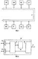
- a typical modular programmable logic controller consists of a power supply module PS and a central processing unit CPU as well as peripheral modules 1.
- the peripheral modules 1 include, for example, digital input modules DE, digital output modules DA, analog input modules AE, analog output modules AA and intelligent peripheral modules IP, e.g. B. controller modules, and at least one intelligent peripheral module or subunit IUE.
- the peripheral modules 1 are connected to the CPU via the system bus 2 and are also supplied with power via the system bus 2.
- Typical examples of such PLCs are the Siemens automation systems SIMATIC S5-115 U, S5-135 U or S5-155 U.
- the PLC according to FIG 1 controls a technical process. Both the structure and function of the PLC, with the exception of the intelligent IUE subunit, are conventional in nature. It is therefore not discussed in more detail below.
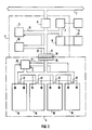
- the intelligent subunit IUE has a processor part 3 and a module part 4.
- the processor part 3 has a processor 5, a bus controller 6 designed as a bus interface unit, a programming interface 7, a user memory interface 8, a module part interface 9 and a memory 10, which are connected to one another via the internal bus 11.
- a programming device 12 can be connected to the processor part 3 via the programming interface 7, so that the intelligent subunit IUE can be programmed and operated completely independently of the rest of the PLC.
- the control program for the processor 5 is written directly into the memory 10.
- the processor part 3 is via its module part interface 9, a connecting element 14, for. B. a plug or a ribbon cable, and the processor interface 15 of the module part 4 connected to the module part 4.
- the module part 4 has several, for. B. four, slots or module receptacles 16 with module interfaces 17 via which plug-in function modules to be inserted into the slots 16 are connected to the internal bus 11 of the processor part.
- the module interfaces 17 are essentially all of the same electrical and mechanical design. They have a large number of contact points, some of which, however, do not have to be connected to the internal bus 11.
- interrupt controller 20 is on the one hand the internal bus 11 and on the other hand connected via line 21 to an interrupt input of processor 5. Because the interrupt controller first evaluates pending interrupts, then reports this to the processor 5 via its own interrupt and then can transmit an interrupt vector to the processor 5 via the internal bus 11, the number of lines required for the connecting element 14 and the contacts can be increased the associated interfaces 9 and 15 can be significantly reduced.
- the slot bus contact points 18 and the interrupt contact points 19 described above are integral components of the module interfaces 17. However, for the sake of better illustration, they have been drawn separately from the module interfaces 17.
- the intelligent subunit IUE consists of two separate boards 22, 23 which can be screwed together using spacer bolts, not shown. Of course, a single board solution can also be chosen.
- the module sub-interface 9, the connecting element 14 and the processor sub-interface 15 are also not shown in FIG. 3.
- the module sub-board 23 is equipped with four different, exemplary function modules 24 to 27.
- the function module 24 is a mixed digital input / output module.
- the function module 24 could, however, also be a purely digital input or output module or could be configured differently.
- the function module 25 is an interface module which provides the intelligent subunit IUE with two serial interfaces 25 ', 25''. Via these interfaces 25 ', 25''the intelligent subunit IUE can communicate with other automation systems.
- the function module 26 is designed as an analog input module. However, it could also be designed as an analog output module or as a mixed analog input / output module.
- the function modules are selected according to the requirements. If necessary, two or three digital input / output modules can also be used, for example.
- the function module 27 is a control panel module.
- function modules are, for example, a counter module, a memory module, a signal processor module and an absolute encoder module.
- Both the last-mentioned function modules and the function modules 24 to 27 shown in FIG. 3 can have their own intelligence, in particular a processor or controller, for internal signal preprocessing and relieving the load on the processor 5.
- the processor 5 can access the dual-ported RAM 30 via the internal bus 11. The access takes place by first storing an address in the RAM 30 via the data lines of the internal bus 11 and then accessing the address just stored. Of the Processor 5 can both read data from RAM 30 and write data into RAM 30 and thus parameterize module controller 31.
- the actual control program of the module controller 31 is in the memory 32, the z. B. is designed as an EPROM.
- the controller 31 reads u. a. periodically, e.g. B. in 1 ms cycle, the signals present at the interfaces 33, 33 'and processes them in accordance with the program stored in the memory 32.
- the controller 31 can e.g. B. convert or calculate the instantaneous speed of the measured element from the difference between two read values.
- the controller 31 stores the relevant data in the dual-ported RAM 30 so that the processor 5 can read it.
- the intelligent subunit IUE itself represents a small, modular PLC (including its own “intelligent periphery”). It only has fewer slots 16 than the large "mother PLC", in the present example four.
- the function modules 24 to 27, 29 are also considerably smaller than the peripheral modules of the "mother PLC”.
- the digital input / output module 24 has, for example, only 8 digital inputs and outputs each compared to 32 inputs and outputs of a corresponding module of the "mother PLC".
- slots 16 can, however, be equipped for specific applications.
- the intelligent subunit IUE can be programmed and operated independently of the large PLC for specific applications.
- the intelligent subunit IUE can be operated independently of the central unit CPU of the PLC.
- the internal bus 11 of the intelligent subunit IUE can differ from the external system bus 2 of the PLC both in terms of configuration and in terms of the data rate.
- the internal bus 11 can be clocked at a significantly higher clock rate and z. B. have a data width of 32 bits compared to 8 bits of the external system bus 2.
- the intelligent subunit IUE represents a considerably smaller, but at the same time also a considerably faster PLC. Because of the speed of the intelligent subunit IUE, the intelligent subunit IUE and thus indirectly the PLC can control fast processes that were previously too slow for the PLCs were. Until now, such processes have been controlled by separate special controls. On the other hand, it is now possible to easily and inexpensively integrate such processes into a comprehensive automation concept.
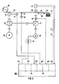
- FIG. 5 An example of such a process is shown in FIG. 5.
- the belt 34 is pulled off the reel 36 by means of the take-off roller 35.
- the take-off roller 35 is driven by the main drive 38 via the main gear 37.
- the main gear 37 has two taps, the second tap being connected to the auxiliary gear 37 '.
- the flying shear 39 in the example a rotating knife, is also driven by the main drive 38 via the auxiliary gear 37 '.
- the belt 34 is therefore cut into pieces 34 'by the flying scissors 39, which are stacked to a stack 41 via the treadmill 40.
- the take-off roller 35 and flying shears 39 run at exactly the same speed.
- the cutting length is neither variable nor adjustable.
- the cutting length is therefore set and varied in that the actuator 38 'is controlled via the current controller 42 during the time interval between two cuts.
- the actuation of the actuator 38 'takes place as follows:
- the signal generator 43 sends a start signal via the line 44 to the digital input module 45 of the intelligent subunit IUE.
- the digital input module 45 then sends an interrupt to the interrupt controller 20 (not shown in FIG. 5), which in turn sends an interrupt to the processor 5 (also not shown in FIG. 5).
- the processor 5 then releases the length control and controls the current controller 42.
- the intelligent subunit IUE can therefore determine the adjustment of the flying scissors 39 relative to the belt 34, if necessary after conversion. When the desired adjustment of the flying shears 39 is reached, the current controller 42 is no longer activated.
- the signal transmitter 43 transmits a stop signal to the digital input module 45 via the line 44 ′.
- line 44 ' is again connected to an interrupt-capable input of input module 45.
- the triggered interrupt causes actuator 38 'to stop, even if the desired adjustment of the flying shears has not yet been achieved.
- the signal can also be used that the angle step generator 51 supplies, which is connected to the take-off roller 35.
- This signal can also be used if necessary.
- a second counter module 52 is required, since each counter module 46, 52 has only two counter inputs.
- a digital input / output module can also be used instead of the digital input module 45.
- an analog input / output module can be used instead of the analog output module 47.
- a wide variety of fast controls, measurement data acquisition, data preprocessing etc. can be connected to a PLC by the intelligent subunit according to the invention.
Landscapes
- Engineering & Computer Science (AREA)
- Mechanical Engineering (AREA)
- Physics & Mathematics (AREA)
- General Physics & Mathematics (AREA)
- Automation & Control Theory (AREA)
- Programmable Controllers (AREA)
- Control By Computers (AREA)
- Selective Calling Equipment (AREA)
Claims (8)
- Système de commande de structure modulaire comportant une sous-unité (IUE) intelligente, notamment une commande à programme enregistré de structure modulaire, comportant un module périphérique intelligent, qui comporte un certain nombre de récepteurs (16) pour des modules fonctionnels (24 à 27, 29, 45 à 47, 52), qui sont sensiblement de même forme électrique et mécanique,- les récepteurs (16) de module comportant des interfaces (17) de module reliées à un bus (11) interne et comportant une multiplicité de points de contact,- les récepteurs (16) de module pouvant être équipés de manière spécifique à l'utilisation de modules fonctionnels (24 à 27, 29, 45 à 47, 52),- les interfaces (17) de module étant reliées entre elles par l'intermédiaire d'un bus (18) à emplacement d'enfichage,- un processeur (5) commandant la sous-unité intelligente (IUE) et une mémoire (10) contenant au moins un programme de processeur étant reliés entre eux dans la sous-unité intelligente (IUE) par l'intermédiaire du bus interne (11),caractérisé en ce que- la sous-unité intelligente (IUE) peut être reliée par l'intermédiaire d'un bus (2) de système externe à une unité centrale (CPU) d'un rang hiérarchique supérieur et comporte une unité (6) d'interface de bus pouvant être reliée au bus (2) de système externe,- le bus interne (11) peut fonctionner à une cadence plus grande que le bus (2) de système externe et- au moins une partie des modules fonctionnels (24 à 27, 29, 45 à 47, 52) comporte une unité intelligente propre (31), par exemple un contrôleur (31).
- Système de commande de structure modulaire suivant la revendication 1, caractérisé en ce que les modules fonctionnels (24 à 27, 29, 45 à 47, 52) sont au moins en partie sous forme de modules numériques ou analogiques d'entrée ou de sortie, éventuellement également de modules d'entrée/sortie numériques ou analogiques.
- Système de commande de structure modulaire suivant la revendication 1 ou 2, caractérisé en ce que quelques uns (19) des points de contact des interfaces (17) des modules sont reliés à une entrée d'interruption du processeur (5).
- Système de commande de structure modulaire suivant la revendication 3, caractérisé en ce qu'un contrôleur (20) d'interruption est disposé entre les quelques points (19) de contact et l'entrée d'interruption.
- Système de commande de structure modulaire suivant l'une des revendications précédentes, caractérisé en ce qu'il comporte au moins un processeur de signaux distinct, de préférence en parallèle avec l'unité centrale (CPU) ou sur un module de processeur de signaux.
- Système de commande de structure modulaire suivant l'une des revendications précédentes, caractérisé en ce que la sous-unité (IUE) intelligente comporte une interface (7) de programmation pour le raccordement d'une unité (12) de programmation, par exemple d'un appareil (12) de programmation.
- Système de commande de structure modulaire suivant l'une des revendications précédentes, caractérisé en ce que les modules fonctionnels (24 à 27, 29, 45 à 47, 52) sont sous forme de modules fonctionnels enfichables.
- Système de commande de structure modulaire suivant l'une des revendications précédentes, caractérisé en ce que la sous-unité intelligente (IUE) est équipée d'un module (47) analogique de sortie ou d'un module analogique d'entrée/sortie, d'un module numérique d'entrée (45) ou d'un module numérique d'entrée/sortie et d'au moins un module (46) de compteur.
Applications Claiming Priority (2)
| Application Number | Priority Date | Filing Date | Title |
|---|---|---|---|
| DE4241338 | 1992-12-08 | ||
| DE4241338 | 1992-12-08 |
Publications (2)
| Publication Number | Publication Date |
|---|---|
| EP0603560A1 EP0603560A1 (fr) | 1994-06-29 |
| EP0603560B1 true EP0603560B1 (fr) | 1997-08-20 |
Family
ID=6474709
Family Applications (1)
| Application Number | Title | Priority Date | Filing Date |
|---|---|---|---|
| EP93118835A Expired - Lifetime EP0603560B1 (fr) | 1992-12-08 | 1993-11-23 | Système de commande modulaire comprenant une sous-unité intelligente |
Country Status (3)
| Country | Link |
|---|---|
| EP (1) | EP0603560B1 (fr) |
| AT (1) | ATE157180T1 (fr) |
| DE (1) | DE59307165D1 (fr) |
Cited By (2)
| Publication number | Priority date | Publication date | Assignee | Title |
|---|---|---|---|---|
| WO2000054119A1 (fr) * | 1999-03-09 | 2000-09-14 | Siemens Aktiengesellschaft | Systeme d'automatisation comportant des objets d'automatisation composes d'elements modulaires |
| US6185477B1 (en) | 1995-09-19 | 2001-02-06 | Siemens Aktiengesellschaft | System for automating the control and regulation of machines and systems in the plastics industry |
Families Citing this family (3)
| Publication number | Priority date | Publication date | Assignee | Title |
|---|---|---|---|---|
| US6289400B1 (en) * | 1998-04-15 | 2001-09-11 | Infineon Technologies Ag | Electrical control device with configurable control modules |
| DE102004056243A1 (de) | 2004-11-22 | 2006-05-24 | Abb Patent Gmbh | Modulares Automatisierungssystem |
| WO2020040721A1 (fr) | 2018-08-20 | 2020-02-27 | Siemens Aktiengesellschaft | Module d'accélération modulaire basé sur un automate programmable industriel pour intelligence artificielle |
Citations (4)
| Publication number | Priority date | Publication date | Assignee | Title |
|---|---|---|---|---|
| US4882702A (en) * | 1986-03-31 | 1989-11-21 | Allen-Bradley Company, Inc. | Programmable controller with I/O expansion module located in one of I/O module positions for communication with outside I/O modules |
| EP0434986A2 (fr) * | 1989-12-22 | 1991-07-03 | Siemens Aktiengesellschaft | Procédé de mise en service d'un élément modulaire à connecter sur un système de commande électronique |
| EP0473086A1 (fr) * | 1990-08-31 | 1992-03-04 | Allen-Bradley Company, Inc. | Processeur pour un appareil de commande programmable |
| EP0490864A1 (fr) * | 1990-12-11 | 1992-06-17 | Fisher Controls International, Inc. | Dispositif de commande avec des unités d'entrées/sorties modulaires |
Family Cites Families (6)
| Publication number | Priority date | Publication date | Assignee | Title |
|---|---|---|---|---|
| IT1062827B (it) * | 1976-03-29 | 1985-02-11 | Olivetti Controllo Numerico | Sistema di controllo numerico per macchine utensili |
| US4442504A (en) * | 1981-03-09 | 1984-04-10 | Allen-Bradley Company | Modular programmable controller |
| CA1211543A (fr) * | 1982-09-24 | 1986-09-16 | John J. Power | Systeme de commande et de regulation d'entrainements electriques |
| EP0207175A1 (fr) * | 1985-06-01 | 1987-01-07 | Karl Mohr | Machine à découper avec un dispositif de commande à ordinateur |
| US5062052B1 (en) * | 1989-06-20 | 1997-11-18 | Cincinnati Milacron Inc | Logic controlled plastic molding machine with programmable operator interface |
| DE645685T1 (de) * | 1989-08-31 | 1995-11-09 | Yokogawa Electric Corp | Verfahren zur Steuerung eines Line Computers zur Durchführung und Relokierung eines übersetztes Programms aus einer Datenspeichersammlung. |
-
1993
- 1993-11-23 AT AT93118835T patent/ATE157180T1/de not_active IP Right Cessation
- 1993-11-23 DE DE59307165T patent/DE59307165D1/de not_active Expired - Fee Related
- 1993-11-23 EP EP93118835A patent/EP0603560B1/fr not_active Expired - Lifetime
Patent Citations (4)
| Publication number | Priority date | Publication date | Assignee | Title |
|---|---|---|---|---|
| US4882702A (en) * | 1986-03-31 | 1989-11-21 | Allen-Bradley Company, Inc. | Programmable controller with I/O expansion module located in one of I/O module positions for communication with outside I/O modules |
| EP0434986A2 (fr) * | 1989-12-22 | 1991-07-03 | Siemens Aktiengesellschaft | Procédé de mise en service d'un élément modulaire à connecter sur un système de commande électronique |
| EP0473086A1 (fr) * | 1990-08-31 | 1992-03-04 | Allen-Bradley Company, Inc. | Processeur pour un appareil de commande programmable |
| EP0490864A1 (fr) * | 1990-12-11 | 1992-06-17 | Fisher Controls International, Inc. | Dispositif de commande avec des unités d'entrées/sorties modulaires |
Cited By (3)
| Publication number | Priority date | Publication date | Assignee | Title |
|---|---|---|---|---|
| US6185477B1 (en) | 1995-09-19 | 2001-02-06 | Siemens Aktiengesellschaft | System for automating the control and regulation of machines and systems in the plastics industry |
| WO2000054119A1 (fr) * | 1999-03-09 | 2000-09-14 | Siemens Aktiengesellschaft | Systeme d'automatisation comportant des objets d'automatisation composes d'elements modulaires |
| US7596575B2 (en) | 1999-03-09 | 2009-09-29 | Siemens Aktiengesellschaft | Automation system with automation objects consisting of module components |
Also Published As
| Publication number | Publication date |
|---|---|
| ATE157180T1 (de) | 1997-09-15 |
| DE59307165D1 (de) | 1997-09-25 |
| EP0603560A1 (fr) | 1994-06-29 |
Similar Documents
| Publication | Publication Date | Title |
|---|---|---|
| EP0678796B1 (fr) | Automate programmable compact et unité centrale d'un automate programmable modulaire | |
| EP0824231B2 (fr) | Système de fabrication | |
| DE2713400C3 (de) | Numerisches Steuersystem für Bearbeitungszentren | |
| EP1174781B1 (fr) | Appareil de transmission de signal | |
| EP2016470B1 (fr) | Terminal de commande pour l'echange d'informations avec un appareil sur site dans un systeme d'automatisation | |
| EP0107026B1 (fr) | Dispositif de commande à programme enregistré | |
| DE3390136T1 (de) | Mikroprozessorgestützter Niedersufen-Anlagenregler | |
| DE2137822A1 (de) | Numerische Werkzeugmaschinensteue rung | |
| DE69913033T2 (de) | Steuerungssystem mit Schnittstelle für Ein/Ausgabekarte | |
| DE9218421U1 (de) | Modular aufgebautes Steuerungssystem mit einer intelligenten Untereinheit | |
| AT522653B1 (de) | Verfahren zur Darstellung und Bedienung von Produktionsmitteln, insbesondere für die kunststoffverarbeitende Industrie | |
| DE3881825T2 (de) | Numerische steuereinheit für laser. | |
| EP0782722A1 (fr) | Procede et dispositif permettant de commander et d'activer des detecteurs et/ou des organes d'actionnement relies par un systeme de bus | |
| EP0603560A1 (fr) | Système de commande modulaire comprenant une sous-unité intelligente | |
| DE29907909U1 (de) | Einsteckkarte und integriertes Überwachungssystem für Prozesse | |
| EP0068482A1 (fr) | Système de contrôle, particulièrement pour installations automatiques de fabrication | |
| DE3319130C2 (de) | Programmierbare Steuerung | |
| EP0903654A2 (fr) | Système de commande, en particulier pour une installation de pallettisation comprenant un robot | |
| DE1563727A1 (de) | Steuersystem | |
| EP0647891A2 (fr) | Unité d'entrée pour un système d'automatisation modulaire | |
| AT398921B (de) | Lötkopf | |
| DE2927254A1 (de) | Numerische rechnersteuerung fuer werkzeugmaschinen | |
| DE4026413C2 (de) | Positionier-Steuervorrichtung | |
| DE2822938A1 (de) | Steuerungs- und ueberwachungseinrichtung | |
| DE3440917C2 (fr) |
Legal Events
| Date | Code | Title | Description |
|---|---|---|---|
| PUAI | Public reference made under article 153(3) epc to a published international application that has entered the european phase |
Free format text: ORIGINAL CODE: 0009012 |
|
| AK | Designated contracting states |
Kind code of ref document: A1 Designated state(s): AT BE CH DE FR GB IT LI NL SE |
|
| 17P | Request for examination filed |
Effective date: 19940719 |
|
| 17Q | First examination report despatched |
Effective date: 19951109 |
|
| GRAG | Despatch of communication of intention to grant |
Free format text: ORIGINAL CODE: EPIDOS AGRA |
|
| GRAH | Despatch of communication of intention to grant a patent |
Free format text: ORIGINAL CODE: EPIDOS IGRA |
|
| GRAH | Despatch of communication of intention to grant a patent |
Free format text: ORIGINAL CODE: EPIDOS IGRA |
|
| GRAA | (expected) grant |
Free format text: ORIGINAL CODE: 0009210 |
|
| AK | Designated contracting states |
Kind code of ref document: B1 Designated state(s): AT BE CH DE FR GB IT LI NL SE |
|
| REF | Corresponds to: |
Ref document number: 157180 Country of ref document: AT Date of ref document: 19970915 Kind code of ref document: T |
|
| REG | Reference to a national code |
Ref country code: CH Ref legal event code: NV Representative=s name: SIEMENS SCHWEIZ AG Ref country code: CH Ref legal event code: EP |
|
| REF | Corresponds to: |
Ref document number: 59307165 Country of ref document: DE Date of ref document: 19970925 |
|
| ET | Fr: translation filed | ||
| GBT | Gb: translation of ep patent filed (gb section 77(6)(a)/1977) |
Effective date: 19970929 |
|
| ITF | It: translation for a ep patent filed | ||
| PLBE | No opposition filed within time limit |
Free format text: ORIGINAL CODE: 0009261 |
|
| STAA | Information on the status of an ep patent application or granted ep patent |
Free format text: STATUS: NO OPPOSITION FILED WITHIN TIME LIMIT |
|
| 26N | No opposition filed | ||
| REG | Reference to a national code |
Ref country code: GB Ref legal event code: IF02 |
|
| PGFP | Annual fee paid to national office [announced via postgrant information from national office to epo] |
Ref country code: DE Payment date: 20040119 Year of fee payment: 11 |
|
| PGFP | Annual fee paid to national office [announced via postgrant information from national office to epo] |
Ref country code: CH Payment date: 20040206 Year of fee payment: 11 |
|
| PGFP | Annual fee paid to national office [announced via postgrant information from national office to epo] |
Ref country code: AT Payment date: 20041020 Year of fee payment: 12 |
|
| PGFP | Annual fee paid to national office [announced via postgrant information from national office to epo] |
Ref country code: SE Payment date: 20041109 Year of fee payment: 12 Ref country code: GB Payment date: 20041109 Year of fee payment: 12 |
|
| PGFP | Annual fee paid to national office [announced via postgrant information from national office to epo] |
Ref country code: NL Payment date: 20041111 Year of fee payment: 12 |
|
| PGFP | Annual fee paid to national office [announced via postgrant information from national office to epo] |
Ref country code: BE Payment date: 20041117 Year of fee payment: 12 Ref country code: FR Payment date: 20041117 Year of fee payment: 12 |
|
| PG25 | Lapsed in a contracting state [announced via postgrant information from national office to epo] |
Ref country code: LI Free format text: LAPSE BECAUSE OF NON-PAYMENT OF DUE FEES Effective date: 20041130 Ref country code: CH Free format text: LAPSE BECAUSE OF NON-PAYMENT OF DUE FEES Effective date: 20041130 |
|
| PG25 | Lapsed in a contracting state [announced via postgrant information from national office to epo] |
Ref country code: DE Free format text: LAPSE BECAUSE OF NON-PAYMENT OF DUE FEES Effective date: 20050601 |
|
| REG | Reference to a national code |
Ref country code: CH Ref legal event code: PL |
|
| PG25 | Lapsed in a contracting state [announced via postgrant information from national office to epo] |
Ref country code: IT Free format text: LAPSE BECAUSE OF NON-PAYMENT OF DUE FEES;WARNING: LAPSES OF ITALIAN PATENTS WITH EFFECTIVE DATE BEFORE 2007 MAY HAVE OCCURRED AT ANY TIME BEFORE 2007. THE CORRECT EFFECTIVE DATE MAY BE DIFFERENT FROM THE ONE RECORDED. Effective date: 20051123 Ref country code: GB Free format text: LAPSE BECAUSE OF NON-PAYMENT OF DUE FEES Effective date: 20051123 Ref country code: AT Free format text: LAPSE BECAUSE OF NON-PAYMENT OF DUE FEES Effective date: 20051123 |
|
| PG25 | Lapsed in a contracting state [announced via postgrant information from national office to epo] |
Ref country code: SE Free format text: LAPSE BECAUSE OF NON-PAYMENT OF DUE FEES Effective date: 20051124 |
|
| PG25 | Lapsed in a contracting state [announced via postgrant information from national office to epo] |
Ref country code: BE Free format text: LAPSE BECAUSE OF NON-PAYMENT OF DUE FEES Effective date: 20051130 |
|
| PG25 | Lapsed in a contracting state [announced via postgrant information from national office to epo] |
Ref country code: NL Free format text: LAPSE BECAUSE OF NON-PAYMENT OF DUE FEES Effective date: 20060601 |
|
| EUG | Se: european patent has lapsed | ||
| GBPC | Gb: european patent ceased through non-payment of renewal fee |
Effective date: 20051123 |
|
| PG25 | Lapsed in a contracting state [announced via postgrant information from national office to epo] |
Ref country code: FR Free format text: LAPSE BECAUSE OF NON-PAYMENT OF DUE FEES Effective date: 20060731 |
|
| NLV4 | Nl: lapsed or anulled due to non-payment of the annual fee |
Effective date: 20060601 |
|
| REG | Reference to a national code |
Ref country code: FR Ref legal event code: ST Effective date: 20060731 |
|
| BERE | Be: lapsed |
Owner name: *SIEMENS A.G. Effective date: 20051130 |