EP0603617A1 - Rasoir à sec avec une tondeuse pivotante - Google Patents
Rasoir à sec avec une tondeuse pivotante Download PDFInfo
- Publication number
- EP0603617A1 EP0603617A1 EP93119578A EP93119578A EP0603617A1 EP 0603617 A1 EP0603617 A1 EP 0603617A1 EP 93119578 A EP93119578 A EP 93119578A EP 93119578 A EP93119578 A EP 93119578A EP 0603617 A1 EP0603617 A1 EP 0603617A1
- Authority
- EP
- European Patent Office
- Prior art keywords
- shaving
- heads
- dry
- head
- shaving head
- Prior art date
- Legal status (The legal status is an assumption and is not a legal conclusion. Google has not performed a legal analysis and makes no representation as to the accuracy of the status listed.)
- Granted
Links
- 230000008878 coupling Effects 0.000 claims description 23
- 238000010168 coupling process Methods 0.000 claims description 23
- 238000005859 coupling reaction Methods 0.000 claims description 23
- 230000006978 adaptation Effects 0.000 description 5
- 230000008901 benefit Effects 0.000 description 5
- 238000006073 displacement reaction Methods 0.000 description 4
- 230000000694 effects Effects 0.000 description 4
- 230000005540 biological transmission Effects 0.000 description 3
- 239000002655 kraft paper Substances 0.000 description 2
- 230000009471 action Effects 0.000 description 1
- 230000015572 biosynthetic process Effects 0.000 description 1
- 230000006735 deficit Effects 0.000 description 1
- 239000011888 foil Substances 0.000 description 1
- 238000000034 method Methods 0.000 description 1
- 230000010355 oscillation Effects 0.000 description 1
- 238000003825 pressing Methods 0.000 description 1
- 230000008569 process Effects 0.000 description 1
- 230000036346 tooth eruption Effects 0.000 description 1
- 230000007704 transition Effects 0.000 description 1
Images


Classifications
-
- B—PERFORMING OPERATIONS; TRANSPORTING
- B26—HAND CUTTING TOOLS; CUTTING; SEVERING
- B26B—HAND-HELD CUTTING TOOLS NOT OTHERWISE PROVIDED FOR
- B26B19/00—Clippers or shavers operating with a plurality of cutting edges, e.g. hair clippers, dry shavers
- B26B19/02—Clippers or shavers operating with a plurality of cutting edges, e.g. hair clippers, dry shavers of the reciprocating-cutter type
- B26B19/04—Cutting heads therefor; Cutters therefor; Securing equipment thereof
- B26B19/046—Cutters being movable in the cutting head
-
- B—PERFORMING OPERATIONS; TRANSPORTING
- B26—HAND CUTTING TOOLS; CUTTING; SEVERING
- B26B—HAND-HELD CUTTING TOOLS NOT OTHERWISE PROVIDED FOR
- B26B19/00—Clippers or shavers operating with a plurality of cutting edges, e.g. hair clippers, dry shavers
- B26B19/02—Clippers or shavers operating with a plurality of cutting edges, e.g. hair clippers, dry shavers of the reciprocating-cutter type
- B26B19/04—Cutting heads therefor; Cutters therefor; Securing equipment thereof
- B26B19/10—Cutting heads therefor; Cutters therefor; Securing equipment thereof involving two or more different types of reciprocating cutting elements, e.g. a pair of toothed shearing elements combined with a pair of perforated cutting elements or a combined toothed and perforated cutting assembly
Definitions
- the invention relates to a dry shaving apparatus with a drive provided in the housing, at least two shaving heads running in the longitudinal direction essentially parallel to one another, each consisting of an upper knife and a lower knife, which can be moved relatively and essentially parallel to one another.
- a dry shaver of the type mentioned is known from US-A-4,797,997.
- the two upper knives of the shaving heads running parallel to one another are each coupled at the end to a parallelogram joint, the transverse joints of which are pivotably articulated on side parts of a common frame in order to bring about a parallel relative movement of the two shaving heads.
- the lower knives assigned to the upper knives are pivotally coupled to a coupling element and are each pressed against the respective upper knife by a spring.
- the coupling element is coupled to the drive of the razor for the purpose of transmitting an oscillating movement to the two lower knives.
- a dry shaver of the type mentioned is also known from JP-4-132 581 A.
- the two upper knives of the shaving heads running parallel to each other are each resiliently mounted in a common interchangeable frame, such that when exerted on the upper knives differently acting forces each of the upper knives executes a corresponding relative movement with respect to the other upper knife.
- the two The lower cutters of the shaving heads are each resiliently arranged on a coupling element coupled to the drive of the shaving apparatus, the springs provided here pressing the lower cutters against the upper cutters on the one hand and enabling the relative movement of the upper cutters on the other hand.
- the shaving head which is designed as a long hair cutter and has sharp-edged cutting teeth, is extendable between the two outer shaving heads, which are designed as short hair cutter, in order to enable contour cutting of hair.
- the invention has for its object to improve the cutting system of a dry shaver of the type mentioned.
- this object is achieved in that a further shaving head is arranged pivotably between the two shaving heads about an axis Z running parallel to the two shaving heads.
- the solution according to the invention has several advantages.
- the solution enables the arrangement of a further shaving head between two shaving heads that can be moved relatively and parallel to one another and, by means of the pivotable mounting of the shaving head provided between the shaving heads that can be moved relative to one another, ensures an adaptation of its cutting area to the so-called cutting plane, which, due to the respective angular position, adjusts one to the outside Contour of the shear heads movable relative to each other is defined tangent.
- An important advantage according to the invention is, inter alia, that the cutting area which becomes effective with the two shaving heads which can be moved relative to one another of the pivotably mounted shaving head, compared to which, by appropriate design, can perform a different cutting function, for example as a long-hair cutter for cutting long hair lying against the skin, thereby simultaneously cutting long hair and short shaving heads that can be moved relative to one another Hair is guaranteed.
- a preferred embodiment of the invention is characterized in that the axis Z runs through the intersection SP of two straight lines T and G, where T is the common tangent to the outer contour of the two outer shaving heads SK1 and SK2 and G is this tangent T1 in the The middle of the distance A is a straight line intersecting, and A is the distance of the tangential points TP1, TP2 of the tangent T to the outer contour of the two outer shaving heads SK1 and SK2.
- the axis Z runs approximately through the intersection SP of two straight lines T and G, where T is the common tangent to the outer contour of the two outer shaving heads SK1, SK2 and G is this tangent T1 in the
- T is the common tangent to the outer contour of the two outer shaving heads SK1, SK2 and G is this tangent T1 in the
- A is a straight line intersecting, and A is the distance of the tangential points TP1, TP2 of the tangent T to the outer contour of the two outer shaving heads SK1, SK2.
- the shear plane SE formed by the tangent T and the shaving head arranged between them can be pivoted about the axis Z.
- a very important advantage of the invention is that it enables adaptation to differently designed movement systems of two shaving heads which can be moved relative to one another in a very simple manner.
- a simple and inexpensive embodiment of the invention is characterized in that the relative movement of the two outer shaving heads can be controlled by means of a parallelogram joint to which at least one further lever for controlling the pivoting movement of the middle shaving head is articulated.
- the middle shaving head is preferably arranged on the lever.
- the shaving head which is pivotably mounted about the axis Z is arranged so as to be relatively movable with the axis Z relative to at least one of the two outer shaving heads.
- This embodiment of the invention ensures an optimal adaptation of the pivotably mounted shaving head to shaving heads which can be moved relative to one another and which are arranged to be movable relative to one another independently of one another.
- the position of the axis Z of the pivotably mounted shaving head can be changed by means of the relatively movable arrangement by exerting an external force acting on the shaving head with respect to the tangent to the outer contour of the two outer shaving heads .
- the pivoting angle A of the pivotably mounted shaving head corresponds essentially to the respective angle A which the tangent T or shear plane SE placed on the outer contour of the two outer shaving heads assumes to a horizontal straight line H.
- the shaving head which is pivotably mounted about the axis Z, is designed as a long-hair cutter.
- the two shaving heads which are movable relative to one another are known to be designed as short hair cutters.
- the formation of the pivotably mounted shaving head, which is designed as a long hair cutter, automatically ensures a combination shave, that is to say simultaneous cutting of short and long hair.
- the upper knife of the long hair trimmer is essentially U-shaped.
- the pivotable arrangement of the long hair trimmer ensures that the flat outer surface of the upper knife comes into contact with the skin and can be moved over the surface of the skin in order to thread long hair into the shear-active cutting area of the upper knife and lower knife.
- a major advantage of the U-shaped configuration of the upper knife of the long-hair trimmer is that it can be moved over the skin surface in any direction together with the shaving heads designed as short-hair trimmers and is shear-active in all directions of movement.
- the shaving heads arranged parallel to the pivotably mounted shaving head are designed as short hair cutters.
- the pivotably mounted shaving head is coupled to a coupling element which can be pivoted transversely to the longitudinal direction of the shaving heads and which is coupled to a drive element which effects the oscillating movement.
- a coupling element driven by the drive of the dry shaving apparatus on which the shaving heads SK1, SK2 designed as short hair cutters are arranged so as to be movable relative to one another and a drive element for the pivotably mounted shaving head SK3 is provided.
- a coupling element on the one hand enables simple coupling or decoupling with the drive of the dry shaving apparatus and, on the other hand, easy-to-handle coupling or decoupling with or without the lower knives of the shaving heads which can be moved relative to one another.
- each of the shaving heads provided is assigned a coupling element which is coupled to the drive provided in the housing.
- This embodiment enables, for example in conjunction with a drive designed as a double eccentric, an opposing oscillating movement from one of the lower knives to at least one of the other lower knives of the shaving heads provided.
- the shaving heads designed as short hair cutters are arranged so as to be movable relative to one another on a common coupling element coupled to a drive.
- This embodiment enables an opposing oscillation movement of the lower knife of the pivotably mounted shaving head with respect to the lower knife of the shaving heads, which are designed as short hair cutters and can be moved relative to one another.
- FIG. 1 shows, in a schematic representation, two shaving heads SK1, SK2 running parallel to one another in the longitudinal direction and designed as short hair cutters, and a shaving head SK3 arranged between these shaving heads SK1 and SK2 and designed as a long hair cutter.
- the two upper knives 1, 2 of the shaving heads SK1 and SK2 are each coupled at the end to a parallelogram joint P, the transverse joints 3, 4 of which are pivotally coupled via pivot bearings 6, 7, 8 and 9 to two rods 10, 11 running parallel to a vertical straight line G and are pivotally articulated via two further pivot bearings 12, 13 on the side parts S of a common frame 14 - see FIG.
- the tangential plane connecting the two arcuate shaving heads SK1 and SK2 is an imaginary plane, which is referred to below as the shear plane SE.
- the common tangent T to the arc shape of the shaving heads SK1 and SK2, with the tangential points TP1 and TP2, determines the transition from the one hand Shear plane SE into the subsequent arch shapes and, on the other hand, through the distance A that the tangential points TP1 and TP2 have to one another, the width of the shear plane SE, the extent of which in the longitudinal direction of the shaving heads SK1, SK2 depends on their length.
- a straight line G intersects the tangent T at right angles and in the middle of the distance A.
- the pivot axis Z runs parallel to the shaving heads SK1, SK2 and SK3 extending in the longitudinal direction.
- the outer contour of the shaving head SK3, which is pivotally coupled to the parallelogram joint P, tangents the tangent T or shear plane SE and, with the tangent T or shear plane SE, pivots around the axis Z, as shown, for example, in FIG. 2 is shown.
- the two rods 10, 11 move relative to and parallel to each other and parallel to the straight line G, by means of which the intersection point SP is determined for the axis Z and on which the pivot bearings 12 and 13 of the transverse joints 3 and 4 are provided.
- the swivel angle of the pivotably mounted shaving head SK3 corresponds to the respective angle B which the tangent T or shear plane SE applied to the outer contour of the two outer shaving heads SK1 and SK2 corresponds to one that occupies the horizontal line H intersecting the intersection SP.
- the horizontal straight line H is an auxiliary line with which the position of shaving heads SK1, SK2 which can be moved relative to one another is defined in the event of non-action from outside acting forces, that is to say the unloaded starting position of the shaving heads SK1, SK2.
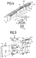
- FIG. 3 shows structural details of the design and arrangement of the shaving heads SK1, SK2 and SK3 according to FIGS and 2 controlling parallelogram joint P is shown.
- Fig. 3 shows a side part S of a frame 14.
- two bolts 17a, 18 are provided which form the pivot bearings 12 and 13 with the bores 19, 20 of the transverse joints 3, 4.
- two bolts 21, 22 are provided, which together with the bores 23, 24 of the rods 10 and 11 form the pivot bearings 7 and 8.
- each further bore 29, 30 is provided which, together with the bolts 30a, 31 provided on the lever 17, form the pivot bearings 15 and 16.
- the upper knives 1 and 2 for example made of shaving foils, of the shaving heads SK1 and SK2 which can be moved relative to one another by means of the rods 10, 11.
- a fastening element 32 is provided on the lever 17, to which the shaving head SK3 designed as a long-hair cutter is fastened - see FIG. 4.
- FIG. 4 shows an embodiment of a pivotable shaving head SK3 with a coupling element 34 which effects the pivoting movement and the drive movement on its lower knife 33.
- the upper knife 36 which is provided with a plurality of slits 35, is fastened at the ends on a carrier element 37, 38.
- the carrier elements 37, 38 serve to fasten the shaving head SK3 to the fastening elements 32 of the levers 17 of the parallelogram joints P provided at the front ends of the shaving heads SK1 and SK2 - see, for example, FIG. 7.
- the upper knife 36 is U-shaped, the one that comes into contact with the skin Is formed flat on the outside, by means of the webs 39 formed by the slots 35, the hair to be cut into the cutting area formed by the upper knife 36 and the lower knife 33 particularly effectively in order to be cut there.
- the lower knife 33 is coupled to the coupling element 34, on which a drive transmission element 40 which is oriented transversely to the direction of vibration of the lower knife 33 is formed.
- a groove 41 is formed in the drive transmission element 40, into which a drive element 43 acted upon by a spring 42 engages.
- the spring 42 and the drive element 43 are arranged in a housing 44 which is directly or indirectly coupled to a drive (not shown) provided in the housing 45 - see FIG. 7 or FIG. 8 - of the dry shaving apparatus.
- the coupling element 34 with the lower knife 33 is held in a resilient contact on the inside of the upper knife 36 via the drive element 43 engaging in the groove 41.
- the arc shape of the inner wall 46 of the groove 41 corresponds to the arc shape of the swivel arc of the shaving head SK3.
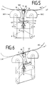
- FIGS. 5, 6 and 7 show a further embodiment of the dry shaving apparatus with a shaving head SK3 which is pivotably mounted about the axis Z and is designed as a long-hair cutter.
- the shaving heads SK1 and SK2 which are designed as short hair cutters, are each coupled at the end to a parallelogram joint P - only one of which is shown schematically.
- the design of the shaving head SK3 arranged between these two shaving heads SK1 and SK2 corresponds to the embodiment according to FIG. 4.
- the lower knives 59, 60 assigned to the upper knives 1 and 2 of the shaving heads SK1, SK2 are spring-mounted on the respective drive pins 61, 62.
- the spring-mounted drive element 43 automatically engages with the groove 41 of the transmission element 40 during the placement process of the completed frame 14 - see FIGS. 4, 5 or 6.
- the outside of the flat upper knife 36 of the The shaving head SK3 has the tangent T. Accordingly, the axis Z, about which the shaving head SK3 is pivotally mounted, lies slightly below the tangent T on the straight line G, that is to say below the intersection point SP of the straight line G with the tangent T. It has been shown that a displacement of the Z axis can be carried out without any appreciable impairment of the pivoting movement of the shaving head SK3 at a certain distance from the intersection point SP shown and described in FIGS. 1 and 2.
- the limits of the permissible distance of the axis Z to the intersection SP can be due to the numerous influencing variables, such as, for example, the outer contour of the shaving head SK3, the friction of its upper knife 36 on the skin, the skin-walking effect of the skin, the distance between the shaving heads SK1 to SK2 and the like, for the respective one Embodiment can be determined by practical tests.
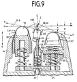
- FIG. 8 shows an exploded view of a further embodiment of a pivotably mounted shaving head SK3.
- a shaving head frame 49 is removably attached.
- a drive element 63 coupled to the drive of the dry shaving apparatus transmits the drive movement via a coupling element 64, which can be coupled to this, via three spring-mounted drive elements 61, 43 and 62 to the lower cutters 59, 33 and 60 of the three shaving heads SK1, SK2 and SK3 via the lower cutters 59 , 33 and 60 provided coupling elements 80, 34 and 81.
- Each of the upper knives 1 and 2 of the shaving heads SK1 and SK2 designed as short hair cutters is movably mounted in the frame 14 which can be coupled to the shaving head frame 49 such that a relative movement of the two shaving heads SK1 and SK2 to one another is ensured.
- An embodiment of such a movable The arrangement of the upper knives 1 and 2 in a frame 14 which can be coupled to a shaving head frame 49 is known, for example, from the document JP-4-132 581 A mentioned in the introduction to the description, which is expressly incorporated by reference here.
- each of the upper knives 1, 2 is resiliently mounted in a frame 14, so that when different external forces are exerted on the upper knives 1, 2, each of the upper knives 1, 2, relative to the other upper knife 1, 2, performs a relative movement.
- This distance X the size of which depends on the force acting on the respective upper knife 1, 2, also arises when both upper knives 1, 2 are evenly subjected to external forces and against the pressure of the springs provided in the frame 14 can be moved in the direction of the shaver housing 45.
- This relative movement of the upper knife 1, 2 also acts against the pressure of the springs, by means of which the respective lower knife 33, 59, 60 are held in contact with the respective upper knife 36, 1, 2.
- These springs are provided between the coupling element transmitting the drive movement and the respective lower knife 33, 59, 60.
- the springs assigned to the lower knives 59, 33, 60 are provided in the coupling element 64 and act on the drive elements 61, 43, 62 or the coupling elements 80, 34, 81.
- the storage of the shaving head SK3 by means of the bearing bolts 47, 48 in the two recesses 68, 69 ensures, on the one hand, the pivoting movement of the shaving head SK3 and a movement of the shaving head SK3 into the frame 14 in the direction of the housing 45.
- the means that shaving heads SK1, SK2, SK3 located in the starting position - as shown in FIGS. 8 and 9 - find a corresponding movement of the shaving heads SK1, SK2 and SK3 from the outside when acting on the outer knives 1, 2, 36 common horizontal straight line H by a distance X, to this horizontal straight line H and thus a displacement of the axis Z of the pivotable shaving head SK3 instead.
- FIG. 9 only one movement variant of three shaving heads SK1, SK2 and SK3 which can be moved independently of one another, for example, is shown schematically, for example.
- the shaving heads SK1 and SK2 are on a common coupling element 64 each against the pressure of one on the upper knife 1, 2 and one on its lower knife 59, 60 acting spring 90, 91 mounted independently of one another so as to be movable.
- the shaving head SK3 arranged between the shaving heads SK1 and SK2 can be moved in the recesses 68, 69 parallel to the direction of the ridges R and can be moved relative to the shaving heads SK1 and SK2 against the pressure of the spring 42 and can be pivoted about the axis Z.
- the shaving head SK2 and the shaving head SK3 move by a corresponding distance X in the direction of the arrow R.
- This movement results in a corresponding displacement of the axis Z within of the recesses 68, 69 and a swiveling movement of the shaving head SK3, the outer contour / upper knife of which automatically adapts to the swiveling angle, which is determined by the angle B which the tangent T or shear plane SE to the outer contour of the two shaving heads SK1 and SK2 to the horizontal line H.
- the three shaving heads SK1, SK2 and SK3 are shifted accordingly by a corresponding distance X from the starting position of the horizontal straight line H in the direction of the arrow R, due to the pivotable mounting of the shaving head SK3 in the recesses 68, 69 the shaving head SK3 assumes a pivoting angle which corresponds to the respective angle B of the tangent T or shear plane SE placed on the outer contour of the two shaving heads SK1 and SK2.
- An additional advantage of the embodiment according to FIGS. 8 and 9 is that the shaving head SK3, which can be moved in the direction of the arrow R against the pressure of a spring and pivotable about the axis Z, can also perform a relative movement with respect to the adjacent shaving heads SK1 and SK2, in particular a Can assume pivot position slightly below the pivot position of the shear plane SE. This favors the constant contact of the three shaving heads SK1, SK2 and SK3 on the skin to be shaved, in particular a continuous adaptation to the constantly changing course of the skin contour to be shaved.
Landscapes
- Life Sciences & Earth Sciences (AREA)
- Forests & Forestry (AREA)
- Engineering & Computer Science (AREA)
- Mechanical Engineering (AREA)
- Dry Shavers And Clippers (AREA)
- Brushes (AREA)
Applications Claiming Priority (2)
| Application Number | Priority Date | Filing Date | Title |
|---|---|---|---|
| DE4244164A DE4244164C2 (de) | 1992-12-24 | 1992-12-24 | Trockenrasierapparat mit einem schwenkbar gelagerten Langhaarschneider |
| DE4244164 | 1992-12-24 |
Publications (2)
| Publication Number | Publication Date |
|---|---|
| EP0603617A1 true EP0603617A1 (fr) | 1994-06-29 |
| EP0603617B1 EP0603617B1 (fr) | 1997-01-08 |
Family
ID=6476590
Family Applications (1)
| Application Number | Title | Priority Date | Filing Date |
|---|---|---|---|
| EP93119578A Expired - Lifetime EP0603617B1 (fr) | 1992-12-24 | 1993-12-04 | Rasoir à sec avec une tondeuse pivotante |
Country Status (5)
| Country | Link |
|---|---|
| US (1) | US5704126A (fr) |
| EP (1) | EP0603617B1 (fr) |
| JP (1) | JP3514794B2 (fr) |
| AT (1) | ATE147314T1 (fr) |
| DE (2) | DE4244164C2 (fr) |
Cited By (2)
| Publication number | Priority date | Publication date | Assignee | Title |
|---|---|---|---|---|
| US6223438B1 (en) | 1996-07-05 | 2001-05-01 | Braun Gmbh | Dry shaving apparatus |
| US6308414B1 (en) | 1996-07-05 | 2001-10-30 | Braun Gmbh | Dry shaving apparatus |
Families Citing this family (39)
| Publication number | Priority date | Publication date | Assignee | Title |
|---|---|---|---|---|
| US5611145A (en) * | 1991-12-20 | 1997-03-18 | Wetzel; Matthias | Dry-shaving apparatus |
| JP3699736B2 (ja) * | 1995-01-11 | 2005-09-28 | 株式会社泉精器製作所 | 電気かみそり |
| JP2002052270A (ja) * | 2000-08-11 | 2002-02-19 | Izumi Products Co | 回転式電気かみそり |
| DE10052296C1 (de) * | 2000-10-20 | 2002-04-04 | Braun Gmbh | Elektrisch betriebenes Haarentfernungsgerät mit einer Beleuchtungseinrichtung |
| JP3979052B2 (ja) * | 2001-09-25 | 2007-09-19 | 松下電工株式会社 | 往復式電気かみそり |
| ATE303886T1 (de) * | 2001-11-15 | 2005-09-15 | Matsushita Electric Works Ltd | Trockenrasierer mit schwenkbarem kopf |
| JP4161966B2 (ja) * | 2002-06-17 | 2008-10-08 | 松下電工株式会社 | 電気かみそり |
| DE60204780T2 (de) | 2002-10-01 | 2006-05-18 | The Gillette Co., Boston | Gelenkgetriebe mit virtueller Schwenkachse für Haarentfernungsgerät mit Schwingkopf |
| GB2393679A (en) * | 2002-10-01 | 2004-04-07 | Gillette Man Inc | Linkage mechanism providing a virtual pivot axis for razor apparatus with pivotal head |
| US7137205B2 (en) * | 2002-10-01 | 2006-11-21 | The Gillette Company | Linkage mechanism providing a virtual pivot axis for razor apparatus with pivotal head |
| US8627573B2 (en) | 2002-10-05 | 2014-01-14 | Braun Gmbh | Hair-removing device |
| DE10246519A1 (de) * | 2002-10-05 | 2004-04-15 | Braun Gmbh | Haarentfernungsgerät |
| JP2005040358A (ja) * | 2003-07-22 | 2005-02-17 | Matsushita Electric Works Ltd | シェーバー |
| JP4597989B2 (ja) * | 2003-08-27 | 2010-12-15 | コーニンクレッカ フィリップス エレクトロニクス エヌ ヴィ | 短毛切断装置及び長毛切断装置を備えたシェービング装置 |
| JP4878750B2 (ja) * | 2004-11-25 | 2012-02-15 | 株式会社泉精器製作所 | 往復式電気かみそり |
| DE102006004675A1 (de) * | 2006-02-02 | 2007-08-09 | Braun Gmbh | Elektrisch betriebener Rasierer |
| DE102006030947A1 (de) | 2006-07-05 | 2008-01-10 | Braun Gmbh | Elektrischer Trockenrasierapparat |
| US20080034591A1 (en) * | 2006-08-08 | 2008-02-14 | Kam Fai Fung | Shaver with swivel head |
| JP4265666B2 (ja) * | 2007-02-23 | 2009-05-20 | パナソニック電工株式会社 | 脱毛装置 |
| JP4862768B2 (ja) * | 2007-07-12 | 2012-01-25 | パナソニック電工株式会社 | 電気かみそり |
| DE102008031132A1 (de) * | 2008-07-01 | 2010-01-07 | Braun Gmbh | Elektrisches Kleingerät zum Entfernen von Haaren |
| DE102008048725A1 (de) * | 2008-09-24 | 2010-03-25 | Braun Gmbh | Haarentfernungsgerät mit Vorrichtung zur Vorbereitung der Haut |
| US8341846B1 (en) * | 2008-11-24 | 2013-01-01 | Lonnie Holmes | Hair clippers with electrically adjustable blades |
| JP4955711B2 (ja) * | 2009-01-15 | 2012-06-20 | パナソニック株式会社 | 電気かみそり |
| US8898909B2 (en) * | 2010-08-25 | 2014-12-02 | Spectrum Brands, Inc. | Electric shaver |
| EP2888086B1 (fr) * | 2013-11-05 | 2016-03-16 | Koninklijke Philips N.V. | Dispositif de soins personnels |
| EP2875916B2 (fr) * | 2013-11-22 | 2021-09-29 | Koninklijke Philips N.V. | Unité de montage et appareil de coupe de cheveux |
| EP2875915B1 (fr) * | 2013-11-22 | 2019-05-22 | Koninklijke Philips N.V. | Unité de liaison et appareil de coupe de cheveux |
| EP3305485B1 (fr) | 2016-09-28 | 2019-07-03 | Braun GmbH | Rasoir électrique |
| EP3300861B1 (fr) | 2016-09-28 | 2019-07-03 | Braun GmbH | Dispositif entraîné électriquement |
| EP3300854B1 (fr) | 2016-09-28 | 2020-06-10 | Braun GmbH | Rasoir électrique |
| EP3300863B1 (fr) * | 2016-09-28 | 2020-06-17 | Braun GmbH | Rasoir électrique |
| EP3300843B1 (fr) | 2016-09-28 | 2020-04-15 | Braun GmbH | Rasoir électrique |
| EP3300848B1 (fr) | 2016-09-28 | 2019-10-23 | Braun GmbH | Rasoir électrique |
| EP3403778B1 (fr) * | 2017-05-17 | 2020-01-01 | Panasonic Intellectual Property Management Co., Ltd. | Dispositif de coupe de cheveux |
| EP3546146B1 (fr) * | 2018-03-27 | 2021-08-18 | Braun GmbH | Dispositif d'épilation |
| EP3546155B1 (fr) | 2018-03-29 | 2022-07-20 | Braun GmbH | Dispositif de soins personnels tel qu'un rasoir électrique |
| EP3546154B1 (fr) | 2018-03-29 | 2022-06-01 | Braun GmbH | Rasoir électrique |
| JP2023144697A (ja) * | 2022-03-28 | 2023-10-11 | パナソニックIpマネジメント株式会社 | 刃ユニットおよび電気かみそり |
Citations (6)
| Publication number | Priority date | Publication date | Assignee | Title |
|---|---|---|---|---|
| DE1048509B (de) * | 1956-10-23 | 1959-01-08 | Elektrischer Rasierapparat | |
| DE1553659A1 (de) * | 1967-06-24 | 1971-05-27 | Braun Ag | Elektrisch antreibbarer Trockenrasierapparat mit zwei Scherkoepfen fuer Kurzhaarschnitt |
| US3659342A (en) * | 1969-10-21 | 1972-05-02 | Paul Kobler | Mechanical razors |
| EP0297300A1 (fr) * | 1987-06-27 | 1989-01-04 | Braun Aktiengesellschaft | Rasoir avec un système pivotant de tête de coupe |
| US4797997A (en) * | 1986-11-07 | 1989-01-17 | The Gillette Company | Dry shavers |
| WO1993012916A2 (fr) * | 1991-12-20 | 1993-07-08 | The Gillette Company | Appareil de rasage a sec |
Family Cites Families (10)
| Publication number | Priority date | Publication date | Assignee | Title |
|---|---|---|---|---|
| US2629169A (en) * | 1947-02-05 | 1953-02-24 | Jacob L Kleinman | Shaving implement |
| US2780864A (en) * | 1953-02-20 | 1957-02-12 | Jacob L Kleinman | Shaving implements |
| CH370673A (de) * | 1959-08-24 | 1963-07-15 | Kobler & Co | Trockenrasierapparat |
| US3967372A (en) * | 1972-03-31 | 1976-07-06 | Sunbeam Corporation | Shaver with adjustable long hair trimmer |
| US3827144A (en) * | 1973-05-24 | 1974-08-06 | Sperry Rand Corp | Shaver cutter head |
| US3911572A (en) * | 1974-06-14 | 1975-10-14 | Sperry Rand Corp | Trimmer device for an electric dry shaver |
| US4274199A (en) * | 1979-01-02 | 1981-06-23 | Sunbeam Corporation | Electric shaver |
| JPH04132581A (ja) * | 1990-09-25 | 1992-05-06 | Matsushita Electric Works Ltd | 往復式電気かみそり |
| US5185926A (en) * | 1992-02-07 | 1993-02-16 | Remington Products, Inc. | Multiple foil and cutting blade assembly for electric dry shavers |
| US5398412A (en) * | 1992-04-23 | 1995-03-21 | Matsushita Electric Works, Ltd. | Reciprocatory dry shaver |
-
1992
- 1992-12-24 DE DE4244164A patent/DE4244164C2/de not_active Expired - Fee Related
-
1993
- 1993-12-04 DE DE59305070T patent/DE59305070D1/de not_active Expired - Fee Related
- 1993-12-04 EP EP93119578A patent/EP0603617B1/fr not_active Expired - Lifetime
- 1993-12-04 AT AT93119578T patent/ATE147314T1/de not_active IP Right Cessation
- 1993-12-22 JP JP32514793A patent/JP3514794B2/ja not_active Expired - Fee Related
-
1995
- 1995-09-14 US US08/528,058 patent/US5704126A/en not_active Expired - Fee Related
Patent Citations (6)
| Publication number | Priority date | Publication date | Assignee | Title |
|---|---|---|---|---|
| DE1048509B (de) * | 1956-10-23 | 1959-01-08 | Elektrischer Rasierapparat | |
| DE1553659A1 (de) * | 1967-06-24 | 1971-05-27 | Braun Ag | Elektrisch antreibbarer Trockenrasierapparat mit zwei Scherkoepfen fuer Kurzhaarschnitt |
| US3659342A (en) * | 1969-10-21 | 1972-05-02 | Paul Kobler | Mechanical razors |
| US4797997A (en) * | 1986-11-07 | 1989-01-17 | The Gillette Company | Dry shavers |
| EP0297300A1 (fr) * | 1987-06-27 | 1989-01-04 | Braun Aktiengesellschaft | Rasoir avec un système pivotant de tête de coupe |
| WO1993012916A2 (fr) * | 1991-12-20 | 1993-07-08 | The Gillette Company | Appareil de rasage a sec |
Cited By (4)
| Publication number | Priority date | Publication date | Assignee | Title |
|---|---|---|---|---|
| US6223438B1 (en) | 1996-07-05 | 2001-05-01 | Braun Gmbh | Dry shaving apparatus |
| US6308414B1 (en) | 1996-07-05 | 2001-10-30 | Braun Gmbh | Dry shaving apparatus |
| US6615492B2 (en) | 1996-07-05 | 2003-09-09 | Braun Gmbh | Dry shaving apparatus |
| US7237339B2 (en) | 1996-07-05 | 2007-07-03 | Brann Gmbh | Dry shaving apparatus |
Also Published As
| Publication number | Publication date |
|---|---|
| JP3514794B2 (ja) | 2004-03-31 |
| DE59305070D1 (de) | 1997-02-20 |
| EP0603617B1 (fr) | 1997-01-08 |
| JPH06233873A (ja) | 1994-08-23 |
| ATE147314T1 (de) | 1997-01-15 |
| US5704126A (en) | 1998-01-06 |
| DE4244164C2 (de) | 1995-09-07 |
| DE4244164C1 (en) | 1993-07-15 |
Similar Documents
| Publication | Publication Date | Title |
|---|---|---|
| EP0603617B1 (fr) | Rasoir à sec avec une tondeuse pivotante | |
| DE69224440T3 (de) | Trockenrasierapparat | |
| EP0239920B1 (fr) | Rasoir électrique à tête de rasage pivotante | |
| DE69019680T2 (de) | Schwingkopf-Sicherheitsrasierer. | |
| EP1017546B1 (fr) | Rasoir electrique | |
| DE69303690T2 (de) | Schneidvorrichtung | |
| DE3721243C2 (fr) | ||
| DE69703844T2 (de) | Trockenrasierer | |
| DE19543095C1 (de) | Trockenrasierapparat | |
| EP0521295B1 (fr) | Tête de rasage, en particulier une unité de lames pour rasoir mécanique | |
| DE69433024T2 (de) | Schneidvorrichtungen für elektrische Haarschneidemaschine | |
| DE102006010323A1 (de) | Trockenrasierer mit schwenkbarem Scherkopf | |
| DE4128218C1 (fr) | ||
| EP0008483B1 (fr) | Tondeuse, en particulier pour rasoir électrique | |
| DE3218799C2 (de) | Vorrichtung zur Halterung des Obermessers einer Schwingschnitt-Tafelblechschere | |
| DE1553814C3 (de) | Elektrisches Trockenrasiergerät | |
| EP0529406B1 (fr) | Rasoir à sec | |
| DE750189C (de) | Schervorrichtung fuer Langdraht | |
| AT401150B (de) | Gerät zum schneiden von haaren | |
| DE3917849C1 (fr) | ||
| DE2019746A1 (de) | Trockenrasierapparat | |
| DE4303426C2 (de) | Elektrisches Trockenrasiergerät | |
| DE1582376C3 (de) | Mähmaschine | |
| DE1553790C3 (de) | Scherkopf für Trockenrasierapparate | |
| DE1582376B2 (de) | Maehmaschine |
Legal Events
| Date | Code | Title | Description |
|---|---|---|---|
| PUAI | Public reference made under article 153(3) epc to a published international application that has entered the european phase |
Free format text: ORIGINAL CODE: 0009012 |
|
| AK | Designated contracting states |
Kind code of ref document: A1 Designated state(s): AT CH DE FR GB IT LI NL |
|
| 17P | Request for examination filed |
Effective date: 19940721 |
|
| 17Q | First examination report despatched |
Effective date: 19950918 |
|
| RAP1 | Party data changed (applicant data changed or rights of an application transferred) |
Owner name: BRAUN AKTIENGESELLSCHAFT |
|
| GRAG | Despatch of communication of intention to grant |
Free format text: ORIGINAL CODE: EPIDOS AGRA |
|
| GRAH | Despatch of communication of intention to grant a patent |
Free format text: ORIGINAL CODE: EPIDOS IGRA |
|
| GRAH | Despatch of communication of intention to grant a patent |
Free format text: ORIGINAL CODE: EPIDOS IGRA |
|
| GRAA | (expected) grant |
Free format text: ORIGINAL CODE: 0009210 |
|
| ITF | It: translation for a ep patent filed | ||
| AK | Designated contracting states |
Kind code of ref document: B1 Designated state(s): AT CH DE FR GB IT LI NL |
|
| REF | Corresponds to: |
Ref document number: 147314 Country of ref document: AT Date of ref document: 19970115 Kind code of ref document: T |
|
| REG | Reference to a national code |
Ref country code: CH Ref legal event code: NV Representative=s name: PATENTANWALTSBUREAU BOSSHARD UND LUCHS Ref country code: CH Ref legal event code: EP |
|
| GBT | Gb: translation of ep patent filed (gb section 77(6)(a)/1977) |
Effective date: 19970108 |
|
| REF | Corresponds to: |
Ref document number: 59305070 Country of ref document: DE Date of ref document: 19970220 |
|
| ET | Fr: translation filed | ||
| PLBE | No opposition filed within time limit |
Free format text: ORIGINAL CODE: 0009261 |
|
| STAA | Information on the status of an ep patent application or granted ep patent |
Free format text: STATUS: NO OPPOSITION FILED WITHIN TIME LIMIT |
|
| 26N | No opposition filed | ||
| REG | Reference to a national code |
Ref country code: FR Ref legal event code: CD Ref country code: FR Ref legal event code: CA |
|
| REG | Reference to a national code |
Ref country code: CH Ref legal event code: PFA Free format text: BRAUN AKTIENGESELLSCHAFT TRANSFER- BRAUN AKTIENGESELLSCHAFT;BRAUN GMBH Ref country code: CH Ref legal event code: NV Representative=s name: PATENTANWALTSBUREAU BOSSHARD UND LUCHS;LUCHS & PAR |
|
| REG | Reference to a national code |
Ref country code: GB Ref legal event code: IF02 |
|
| PGFP | Annual fee paid to national office [announced via postgrant information from national office to epo] |
Ref country code: GB Payment date: 20021125 Year of fee payment: 10 |
|
| PGFP | Annual fee paid to national office [announced via postgrant information from national office to epo] |
Ref country code: FR Payment date: 20021217 Year of fee payment: 10 |
|
| PGFP | Annual fee paid to national office [announced via postgrant information from national office to epo] |
Ref country code: CH Payment date: 20021230 Year of fee payment: 10 |
|
| PG25 | Lapsed in a contracting state [announced via postgrant information from national office to epo] |
Ref country code: GB Free format text: LAPSE BECAUSE OF NON-PAYMENT OF DUE FEES Effective date: 20031204 |
|
| PGFP | Annual fee paid to national office [announced via postgrant information from national office to epo] |
Ref country code: AT Payment date: 20031219 Year of fee payment: 11 |
|
| PGFP | Annual fee paid to national office [announced via postgrant information from national office to epo] |
Ref country code: NL Payment date: 20031223 Year of fee payment: 11 |
|
| PG25 | Lapsed in a contracting state [announced via postgrant information from national office to epo] |
Ref country code: LI Free format text: LAPSE BECAUSE OF NON-PAYMENT OF DUE FEES Effective date: 20031231 Ref country code: CH Free format text: LAPSE BECAUSE OF NON-PAYMENT OF DUE FEES Effective date: 20031231 |
|
| GBPC | Gb: european patent ceased through non-payment of renewal fee |
Effective date: 20031204 |
|
| REG | Reference to a national code |
Ref country code: CH Ref legal event code: PL |
|
| PG25 | Lapsed in a contracting state [announced via postgrant information from national office to epo] |
Ref country code: FR Free format text: LAPSE BECAUSE OF NON-PAYMENT OF DUE FEES Effective date: 20040831 |
|
| REG | Reference to a national code |
Ref country code: FR Ref legal event code: ST |
|
| PG25 | Lapsed in a contracting state [announced via postgrant information from national office to epo] |
Ref country code: AT Free format text: LAPSE BECAUSE OF NON-PAYMENT OF DUE FEES Effective date: 20041204 |
|
| PG25 | Lapsed in a contracting state [announced via postgrant information from national office to epo] |
Ref country code: NL Free format text: LAPSE BECAUSE OF NON-PAYMENT OF DUE FEES Effective date: 20050701 |
|
| NLV4 | Nl: lapsed or anulled due to non-payment of the annual fee |
Effective date: 20050701 |
|
| PGFP | Annual fee paid to national office [announced via postgrant information from national office to epo] |
Ref country code: DE Payment date: 20051203 Year of fee payment: 13 |
|
| PG25 | Lapsed in a contracting state [announced via postgrant information from national office to epo] |
Ref country code: IT Free format text: LAPSE BECAUSE OF NON-PAYMENT OF DUE FEES;WARNING: LAPSES OF ITALIAN PATENTS WITH EFFECTIVE DATE BEFORE 2007 MAY HAVE OCCURRED AT ANY TIME BEFORE 2007. THE CORRECT EFFECTIVE DATE MAY BE DIFFERENT FROM THE ONE RECORDED. Effective date: 20051204 |
|
| PG25 | Lapsed in a contracting state [announced via postgrant information from national office to epo] |
Ref country code: DE Free format text: LAPSE BECAUSE OF NON-PAYMENT OF DUE FEES Effective date: 20070703 |