EP0603639B1 - Zwei-Ritzel-Achseinheit - Google Patents
Zwei-Ritzel-Achseinheit Download PDFInfo
- Publication number
- EP0603639B1 EP0603639B1 EP93119740A EP93119740A EP0603639B1 EP 0603639 B1 EP0603639 B1 EP 0603639B1 EP 93119740 A EP93119740 A EP 93119740A EP 93119740 A EP93119740 A EP 93119740A EP 0603639 B1 EP0603639 B1 EP 0603639B1
- Authority
- EP
- European Patent Office
- Prior art keywords
- gear
- axle assembly
- ratio
- axis
- axle
- Prior art date
- Legal status (The legal status is an assumption and is not a legal conclusion. Google has not performed a legal analysis and makes no representation as to the accuracy of the status listed.)
- Expired - Lifetime
Links
- 230000009467 reduction Effects 0.000 claims description 26
- 230000008859 change Effects 0.000 claims description 4
- 230000008901 benefit Effects 0.000 description 9
- 230000000712 assembly Effects 0.000 description 6
- 238000000429 assembly Methods 0.000 description 6
- 230000005540 biological transmission Effects 0.000 description 5
- 238000004519 manufacturing process Methods 0.000 description 3
- 230000033001 locomotion Effects 0.000 description 2
- 239000000654 additive Substances 0.000 description 1
- 230000000996 additive effect Effects 0.000 description 1
- 230000009699 differential effect Effects 0.000 description 1
- 230000004069 differentiation Effects 0.000 description 1
- 238000000926 separation method Methods 0.000 description 1
Images


Classifications
-
- B—PERFORMING OPERATIONS; TRANSPORTING
- B60—VEHICLES IN GENERAL
- B60K—ARRANGEMENT OR MOUNTING OF PROPULSION UNITS OR OF TRANSMISSIONS IN VEHICLES; ARRANGEMENT OR MOUNTING OF PLURAL DIVERSE PRIME-MOVERS IN VEHICLES; AUXILIARY DRIVES FOR VEHICLES; INSTRUMENTATION OR DASHBOARDS FOR VEHICLES; ARRANGEMENTS IN CONNECTION WITH COOLING, AIR INTAKE, GAS EXHAUST OR FUEL SUPPLY OF PROPULSION UNITS IN VEHICLES
- B60K17/00—Arrangement or mounting of transmissions in vehicles
- B60K17/04—Arrangement or mounting of transmissions in vehicles characterised by arrangement, location or kind of gearing
- B60K17/16—Arrangement or mounting of transmissions in vehicles characterised by arrangement, location or kind of gearing of differential gearing
- B60K17/165—Arrangement or mounting of transmissions in vehicles characterised by arrangement, location or kind of gearing of differential gearing provided between independent half axles
-
- F—MECHANICAL ENGINEERING; LIGHTING; HEATING; WEAPONS; BLASTING
- F16—ENGINEERING ELEMENTS AND UNITS; GENERAL MEASURES FOR PRODUCING AND MAINTAINING EFFECTIVE FUNCTIONING OF MACHINES OR INSTALLATIONS; THERMAL INSULATION IN GENERAL
- F16H—GEARING
- F16H48/00—Differential gearings
- F16H48/06—Differential gearings with gears having orbital motion
- F16H48/08—Differential gearings with gears having orbital motion comprising bevel gears
-
- F—MECHANICAL ENGINEERING; LIGHTING; HEATING; WEAPONS; BLASTING
- F16—ENGINEERING ELEMENTS AND UNITS; GENERAL MEASURES FOR PRODUCING AND MAINTAINING EFFECTIVE FUNCTIONING OF MACHINES OR INSTALLATIONS; THERMAL INSULATION IN GENERAL
- F16H—GEARING
- F16H48/00—Differential gearings
- F16H48/06—Differential gearings with gears having orbital motion
- F16H48/08—Differential gearings with gears having orbital motion comprising bevel gears
- F16H2048/082—Differential gearings with gears having orbital motion comprising bevel gears characterised by the arrangement of output shafts
-
- F—MECHANICAL ENGINEERING; LIGHTING; HEATING; WEAPONS; BLASTING
- F16—ENGINEERING ELEMENTS AND UNITS; GENERAL MEASURES FOR PRODUCING AND MAINTAINING EFFECTIVE FUNCTIONING OF MACHINES OR INSTALLATIONS; THERMAL INSULATION IN GENERAL
- F16H—GEARING
- F16H48/00—Differential gearings
- F16H48/38—Constructional details
- F16H48/40—Constructional details characterised by features of the rotating cases
Definitions
- the present invention relates to axle assemblies for driving a pair of independently rotatable axle shafts, and more particularly, to such an arrangement of the type in which differential gear means are provided to permit rotation of the axle shafts at different rotational speeds.
- axle assembly which is intended to be the rear-rear axle of a tandem axle arrangement.
- a "tandem" axle arrangement is one having two separate axle assemblies, for example, toward the rear end of the vehicle, wherein one axle assembly follows the other, in the direction of movement of the vehicle.
- the present invention is not limited to use in an axle assembly which is part of a tandem axle arrangement, but may be used in any axle assembly, including independently rotatable, generally co-axial axle shafts, each shaft being driven by a separate ring gear.
- US-A-2 145 183 shows a final drive gear for vehicles with swinging half-axles.
- the known arrangement comprises two transmission casing sections that are journalled on a common tube-like support structure which accomodates a differential gearing.
- the yoke of the differential is provided in the form of a spur gear and two output shafts are extending from the differential arrangement. Each of both shafts carries at its free end a further spur gear for rotating with the shaft.
- the last mentioned spur gear defines a part of a corresponding parallel axis gear set the output shaft of which supports a pinion gear for rotating therewith.
- the pinion gear engages a ring gear that is coupled to the related axle shaft driving the corresponding driving wheel. Due to this arrangement the load on each ring gear corresponds to substantially one half of the complete driving torque.
- axles having the overall configuration described above, have certain disadvantages.
- the total drive torque, to be delivered to the wheels is transmitted through a single ring gear, thus requiring that ring gear to be quite large and expensive.
- the bearing sets which support that particular ring gear within the axle housing are also required to be quite large and expensive.
- the inter-wheel differential is subjected to the full driving torque (being disposed downstream of the drive pinion-ring gear reduction), thus requiring a larger, much more expensive differential gear set.
- an object of the present invention to provide an axle assembly which utilizes the torque-sharing principles of twin countershaft devices, and which has the performance benefits inherent in twin-countershaft devices, as described above.
- an axle assembly of the type including independently rotatable, generally co-axial first and second axle shafts.
- First and second ring gear means are operable to drive the first and second axle shafts, respectively.
- First and second drive pinion gears are in meshing engagement with the first and second ring gear means, respectively.
- a differential gear means having at least one input pinion gear in driven relationship with an input means, and first and second output gears in meshing engagement with the input pinion gear.
- the first output gear is operable to transmit torque to the first drive pinion gear
- the second output gear is operable to transmit torque to the second drive pinion gear.
- the first output gear transmits torque to the first drive pinion gear through a first parallel axis gear set
- the second output gear transmits torque to the second drive pinion gear through a second parallel axis gear set
- the first and second parallel axis gear sets being substantially identical, and being arranged generally in a mirror image relative to an axis of rotation defined by the first and second axle shafts.
- the first output gear, the first drive pinion gear, the first ring gear means, and the first axle shaft define a first torque path.
- the second output gear, the second drive pinion gear, the second ring gear means, and the second axle shaft define a second torque path.
- the first and second torque paths are arranged generally in a mirror image relative to an axis of rotation defined by the axle shafts.
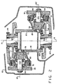
- FIG. 1 is a vertical, axial cross-section, of an axle assembly made in accordance with the present invention.
- FIG. 2 is a horizontal, axial cross-section, taken on line 2-2 of FIG. 1, and on the same scale.
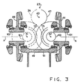
- FIG. 3 is a somewhat schematic transverse cross section, taken generally on line 3-3 of FIG. 1, and on the same scale.
- FIG. 4 is a simplified, schematic view of the axle assembly of the present invention, and is included primarily to illustrate conceptual and spatial relationships of the present invention.
- FIG. 1 illustrates a preferred embodiment of an axle assembly, generally designated 11, of the type which may comprise the rear-rear axle of a tandem rear axle arrangement.
- axle assembly generally designated 11, of the type which may comprise the rear-rear axle of a tandem rear axle arrangement.
- Such an arrangement would typically be used to transmit engine torque from the transmission to the rear drive wheels of a vehicle such as a class 8 truck.
- FIGS. 1 and 2 various parts are omitted from the drawings, primarily to avoid confusion by having some parts showing in the background, partially hidden by certain other parts which are shown in the foreground.
- FIG. 3 is illustrated as being taken on line 3-3 of FIG. 1, primarily because FIG. 3 is drawn as though taken on the axis of rotation of the ring gears and axle shafts.
- FIG. 3 in dotted line are included for illustration purposes, even though such parts would be "behind" the plane of FIG. 3, i.e., toward the forward end (left end) of the axle assembly in FIG. 1.
- the axle assembly 11 includes an axle housing 13 and a front bearing retainer plate 15.
- the retainer plate 15 is bolted to the axle housing 13 by means of a plurality of bolts 17.
- An input shaft 19 extends axially through the retainer plate 15, and is rotatably supported relative to the axle housing 13 by means of a bearing set 21, the bearing set 21 being pressed into a cylindrical opening defined by the retainer plate 15.
- the rearward end (right end in FIG. 1) of the input shaft 19 extends into an interwheel differential set, generally designated 23.
- the differential 23 includes a pinion yoke 25, which is preferably in splined engagement with the portion of the input shaft 19 which extends through the yoke 25.
- the pinion yoke 25 includes a pair of diametrically-opposed stub shafts 27, with an input pinion gear 29 being rotatably disposed on each of the shafts 27, as is generally well known in the differential art.
- Both of the input pinion gears 29 are in meshing engagement with a side gear 31, which is formed at the rearward end of a forward output shaft 33.
- the forward output shaft 33 is hollow, receives the input shaft 19 extending therethrough, and is substantially concentric with the input shaft 19.
- the forward end of the forward output shaft 33 is disposed adjacent the inner race of the bearing set 21.
- the input pinion gears 29 are also in meshing engagement with a side gear 37, which is rotatably supported relative to the axle housing 13 by means of a bearing set 39.
- the side gear 37 is in splined engagement with a rearward output shaft 41, the rearward end of which is rotatably supported relative to the axle housing 13 by means of a bearing set 43.
- the forward end of the rearward output shaft 41 comprises a relatively enlarged portion, defining a pilot bore which receives and pilots therein a pilot portion 45, extending from the rearward end of the input shaft 19.
- a spur gear 47 In splined engagement with the rearward end of the rearward output shaft 41 is a spur gear 47 which, in the subject embodiment, is the same as the spur gear 35, in terms of number of teeth, pitch diameter, etc.
- inter-wheel differential 23 has been illustrated herein as an "open” differential, partly for ease of illustration, those skilled in the art will understand that the invention is not so limited.
- the inter-wheel differential 23 could include some means to limit differentiation between the side gears 31 and 37.
- one of the outputs could be “lockable” relative to the input, as is illustrated and described in above-incorporated U.S. Patent No. 4,432,431.
- the spur gear 35 is in meshing engagement (FIG. 3) with a relatively larger forward spur gear 49, while the spur gear 47 is in meshing engagement (FIG. 3) with a relatively larger, rearward spur gear 51.
- the forward spur gear 49 is in splined engagement with a forward pinion shaft 53, which is rotatably supported relative to the axle housing 13 by means of a pair of tapered roller bearings 55 and 57, the bearings 55 and 57 being pressed into an annular housing insert 59.
- the insert 59 is bolted to the axle housing 13 by means of a plurality of bolts 61.
- the rearward spur gear 51 is in splined engagement with a rearward pinion shaft 63, which is rotatably supported relative to the axle housing 13 by means of a pair of tapered roller bearings 65 and 67.
- the bearings 65 and 67 are pressed into an annular housing insert 69, the insert 69 being attached to the axle housing 13 by means of a plurality of bolts 71.
- the forward pinion shaft 53 has a pinion gear 73 which, preferably, is formed integral with the shaft 53.
- the rearward pinion shaft 63 has a pinion gear 75, preferably formed integral with the shaft 63.
- the rearward end of the forward pinion shaft 53 includes a terminal portion 77 which is rotatably supported by a bearing set 79.
- the bearing set 79 is pressed into a transverse wall 81, which preferably is cast integrally with the axle housing 13.
- the forward end of the rearward pinion shaft 63 includes a terminal portion 83, which is rotatably supported by a bearing set 85, and the bearing set 85 is pressed into a transverse wall 87 which, preferably, is cast integrally with the axle housing 13.
- the forward pinion gear 73 is in meshing engagement with a ring gear 89, while the rearward pinion gear 75 is in meshing engagement with a ring gear 91.
- the ring gear 89 includes a hub portion 93, which preferably defines a set of internal splines for splined engagement with an axle shaft 95 (shown only in FIG. 4).
- the hub portion 93 is rotatably supported relative to the axle housing 13 by means of a pair of tapered roller bearing sets 97 and 99.
- the ring gear 91 includes a hub portion 101 which, preferably, defines a set of internal splines adapted for splined engagement with an axle shaft 103 (shown only in FIG. 4).
- the hub portion 101 is rotatably supported relative to the axle housing 13 by means of a pair of tapered roller bearing sets 105 and 107.
- FIG. 4 in conjunction with FIGS. 1 through 3, the operation of the axle assembly of the present invention will be described.
- the primary purpose of FIG. 4 is to show the axle assembly of the present invention in a somewhat simplified, schematic manner. Although somewhat schematic, FIG. 4 does accurately illustrate various conceptual and spatial relationships which are an important part of the present invention, but which may not be clearly understood from FIGS. 1 through 3.
- FIG. 4 for each gear there is a designation, in parenthesis, of the number of teeth, and for each shaft, there is a designation, in parenthesis, of a particular rotational speed of the shaft.
- these numbers of teeth, and shaft speeds are by way of example only, and apply only to one particular alternative embodiment of the present invention.
- the overall arrangement and configuration shown in FIG. 4 is applicable to all embodiments of the invention.
- the conventional axle assembly includes a ring and pinion (right-angle drive), with the inter-wheel differential being disposed on the "output" side of the ring and pinion combination.
- the relatively high speed, low torque input is transmitted by the input shaft 19 to the inter-wheel differential 23, where the "torque-sharing" and the separation between the torque paths occurs.
- One half of the input torque is then transmitted by the side gear 31 to the spur gear 35, while the other half of the torque is transmitted by the side gear 37 to the spur gear 47.
- each pair of gears comprise a parallel-axis gear set, capable of providing whatever gear reduction, if any, is desired.
- each ring gear 89 or 91 of the present invention transmits only half of the final output torque
- each ring gear is required to be only about one half the volume which would be required for a ring gear to transmit the entire output torque of the axle assembly.
- each of the ring gears 89 and 91, as well as the bearing sets 97, 99, 105, and 107 which support the ring gears can be much smaller and less expensive than would be required in the conventional axle assembly.
- one feature of the present invention is the symmetry of the overall configuration and the fact that various elements of which two are required are identical.
- the spur gears 49 and 51, the pinion shafts 53 and 63, the pinion gears 73 and 75, and the ring gears 89 and 91 can all be identical, and therefore, the same part number.
- the spur gears 35 and 47 are different, although both could have the same overall diameter, pitch diameter, circular pitch, etc.
- axle shafts 95 and 103 define a common axis of rotation A because they are typically substantially co-axial.
- the forward pinion shaft 53 and pinion gear 73 define a first drive pinion axis A1
- the rearward pinion shaft 63 and pinion gear 75 define a second drive pinion axis A2.
- the side gears 31 and 37 and the forward output shaft 33 and rearward output shaft 41 cooperate to define an output gear axis A3.
- the stub shafts 27 define a pinion shaft axis A4, oriented generally perpendicular to the output gear axis A3.
- the first and second drive pinion axes A1 and A2 are equally and oppositely spaced relative to the output gear axis A3 (although both are below the axis A3, as may best be seen in FIG. 3).
- the combination of the spur gears 35 and 49, the pinion gear 73, and the ring gear 89 is arranged, generally in a "mirror image" about the axis of rotation A, relative to the combination of the spur gears 47 and 51, the pinion gear 75, and the ring gear 91.
- the relationship is referred to as being "generally" a mirror image, rather than a perfect mirror image, only because it is not an essential feature of the present invention that the mirror image relationship exist, or if it does, that the relationship comprise a perfect mirror image.
- the invention makes it possible to for the various gears to be arranged in enough of a mirror image, to make it possible for the various torques and reaction forces to be "balanced", i.e., disposed equally and oppositely relative to the axis of rotation A or the pinion shift axis A4.
- the gear mesh between the pinion gear 73 and ring gear 89 be out of phase with the gear mesh between the pinion gear 75 and ring gear 91.
- Such an out of phase relationship will insure that the dynamic pulses generated as the gears go through the gear mesh will not be "additive", i.e., that the pulse between the gears 73 and 89 will not be a maximum at the same time that the pulse between the gears 75 and 91 is a maximum.
- the benefit of the desired out-of-phase relationship is to minimize generated noise.
- the provision of two different torque paths, and two gear sets (and therefore, potentially two different gear ratios) in each path offers many opportunities for dynamic load reduction and noise reduction.
- the likelihood of out-of-phase gear meshes can be increased by putting the forward spur gear 49 at an angular relationship to the pinion gear 73, which is different than the angular relationship of the rearward spur gear 51 to the pinion gear 75.
- the spur gear 35 can be put at an angular relationship to the side gear 31, which is different than the angular relationship of the side gear 37 to the spur gear 47.
- noise could be minimized by providing different gear mesh frequencies for the two pinion gear-ring gear combinations.
- the pinion gear 73 has ten teeth, and the ring gear 89 has 39 teeth (a 3.9 ratio) and the spur gears 35 and 49 have the same number of teeth (for a 1:1 ratio), then the overall ratio for that torque path is 3.9.
- the spur gears 47 and 51 could be selected to provide a gear ratio of approximately 1.054, such that the overall gear ratio for that torque path would also be 3.9.
- the forward output shaft 33 would have a speed of 780 rpm, while the rearward outward shaft 41 would have a speed of 814 rpm.
- 780 rpm plus 814 rpm, divided by two equals 797 rpm.
- the forward pinion shaft 53 would also have a speed of 780 rpm, and dividing that speed by the 3.9 ratio would yield an output for the axle shaft 95 of 200 rpm.
- the rearward pinion shaft 63 would rotate at 740 rpm (814 x 30/33). This speed of 740 rpm for the shaft 63, divided by the 3.7 ratio, would yield an output speed for the axle shaft 103 of 200 rpm.
- the difference in speed between the side gears 31 and 37 would be equal to only about 4.2 percent or the input speed, e.g., in the above example, a difference of about 33 rpm.
- the potential for noise reduction provided by the alternative embodiment described above may be better appreciated by reference to the table below, which indicates, in the last column ("MESH FREQUENCY") the variety of mesh frequencies (in cycles per second) which would occur in the embodiment just described.
- MESH FREQUENCY GEARS TEETH MESH FREQUENCY 73,89 10,39 130 35,49 29,29 377 31,29 16,10 4.53 75,91 10,37 123.3 47,51 30,33 407 37,29 16,10 4.53
- another advantage of the present invention is the ability to "change" gear ratios.
- all of the similar gears e.g., spur gears 49 and 51
- spur gears 49 and 51 have the same number of teeth, pitch, etc.
- all parts would be common (i.e., same part, same part number, etc.), except for the four spur gears 35, 49, 47, and 51.
- axle assembly of the present invention provides a number of advantages and accomplishes the objects set forth in the BACKGROUND OF THE DISCLOSURE.
- the axle assembly of the present invention makes it possible to use a smaller, less expensive, inter-wheel differential gear set than would be required if the differential were disposed "downstream" of the pinion gear-ring gear reduction, and would thus be subjected to a substantially greater torque (by a ratio of about 3.7 or 3.9 in the preceding examples).
- the axle assembly of the present invention also makes it possible to use substantially smaller pinion gears, ring gears, and bearings than would be required in the conventional axle assembly. Finally, there are substantial advantages in the symmetrical, mirror image arrangement of the various gears and shafts of the axle assembly of the present invention, resulting in a symmetrical, mirror image relationship of the two torque paths.
Landscapes
- Engineering & Computer Science (AREA)
- Mechanical Engineering (AREA)
- General Engineering & Computer Science (AREA)
- Chemical & Material Sciences (AREA)
- Combustion & Propulsion (AREA)
- Transportation (AREA)
- Retarders (AREA)
Claims (21)
- Achsanordnung (11) in der Bauart mit:voneinander unabhängig drehbaren, im Wesentlichen zueinander koaxialen ersten und zweiten Achswellen (95, 103), die eine Drehachse (A) definieren;ersten und zweiten Tellerradmitteln (89,91), die konzentrisch bezüglich der Drehachse angeordnet sind und dazu dienen, die erste bzw. die zweite Achswelle (95,103) anzutreiben;einem ersten und einem zweiten Ritzel (73,75), die mit den ersten bzw. zweiten Tellerradmitteln (89,91) kämmend in Eingriff stehen;Ausgleichsgetriebemitteln (23), die wenigstens ein Eingangsritzel (29), das in Antriebsverbindung mit Eingangsmitteln (19,25) steht, und erste und zweite Ausgangszahnrädern (31,37) umfassen, die mit dem Eingangsritzel (29) kämmend in Eingriff stehen; wobeidas erste Ausgangszahnrad (31) dazu dient, das Drehmoment auf das erste Antriebsritzel (73) über eine ersten Zahnradsatz (35, 49) mit parallelen Achsen zu übertragen, und das zweite Ausgangszahnrad (37) dazu dient, über einen zweiten Zahnradsatz (47, 51) der parallelen Achsen Drehmoment auf das zweite Antriebsritzel (75) zu übertragen;wobei der erste und der zweite Zahnradsatz (35, 49; 47, 51) mit parallelen Achsen ein erstes bzw. ein zweites Übersetzungsverhältnis definiert, der erste und der zweite Zahnradsatz (35, 49; 47, 51) mit parallelen Achsen leicht durch einen dritten bzw. vierten Zahnradsatz (35, 49; 47, 51) mit parallelen Achsen ersetzbar ist, der dritte und vierte Zahnradsatz (35, 49; 47, 51) mit parallelen Achsen ein drittes bzw. ein viertes Übersetzungsverhältnis aufweist und das dritte und das vierte Übersetzungsverhältnis sich von dem ersten und dem zweiten Übersetzungsverhältnis unterscheiden, um das Gesamtübersetzungsverhältnis der Achsanordnung (11) ohne weitere wesentliche Änderung an der Achsanordnung (11) zu ändern.
- Achsanordnung (11) nach Anspruch 1, dadurch gekennzeichnet, dass die ersten und zweiten Tellerradmittel im Wesentlichen identische erste (89) und zweite (91) Tellerradglieder aufweisen und dass das erste (73) und das zweite (75) Antriebsritzel im Wesentlichen gleich sind und eine erste (A1) und eine zweite (A2) Antriebsritzelachse definieren, wobei die Antriebsritzelachsen im Wesentlichen zueinander parallel sind.
- Achsanordnung (11) nach Anspruch 2, dadurch gekennzeichnet, dass die erste (A1) und die zweite (A2) Antriebsritzelachse bezüglich der Drehachse (A), die durch die Achswellen (95, 103) definiert ist, zueinander im Wesentlichen spiegelbildlich angeordnet sind.
- Achsanordnung (11) nach Anspruch 2, dadurch gekennzeichnet, dass in jedem Augenblick das erste (89) Tellerradglied und das erste (73) Antriebsritzel einen ersten Zahneingriff und das zweite (91) Tellerradglied und das zweite (75) Antriebsritzel einen zweiten Zahneingriff bilden, wobei der erste und der zweite Zahneingriff nicht in Phase sind.
- Achsanordnung (11) nach Anspruch 1, dadurch gekennzeichnet, dass die Ausgleichsgetriebemittel (23) eine Anzahl von im Wesentlichen identischen Eingangsritzeln (29), die mit dem ersten (31) und dem zweiten (37) Ausgangszahnrad in Eingriff stehen, aufweisen, wobei das erste und das zweite Ausgangszahnrad im Wesentlichen gleich sind und sie eine gemeinsame Ausgangszahnraddrehachse (A3) definieren.
- Achsanordnung (11) nach Anspruch 5, dadurch gekennzeichnet, dass die Ausgangszahnraddrehachse (A3) im Wesentlichen rechtwinklig zu der Drehachse (A) angeordnet ist, die durch die Achswellen (95, 103) definiert ist.
- Achsanordnung (11) nach Anspruch 5, dadurch gekennzeichnet, dass die Ausgleichsgetriebemittel (23) eine Ritzelwelle (27) aufweisen, deren Rotationsachse (A4) rechtwinklig zu der Ausgangszahnraddrehachse (A3) ist und diese schneidet, wobei die Anzahl der Eingangsritzel (29) auf der Ritzelwelle drehbar sind, um drehfest mit dieser um die Drehachse (A4) zu rotieren.
- Achsanordnung (11) nach Anspruch 7, dadurch gekennzeichnet, dass die Eingangsmittel (19) dazu dienen, um in antriebsmäßiger Verbindung mit der Ritzelwelle (27) das gesamte Eingangsantriebsdrehmoment auf die Ritzelwelle zu übertragen.
- Achsanordnung (11) nach Anspruch 8, dadurch gekennzeichnet, dass die Eingangsmittel eine Eingangswelle (19) aufweisen, die zur Antriebsverbindung mit der Ritzelwelle (27) vorgesehen ist und deren Drehachse mit der Ausgangszahnraddrehachse (A3) zusammenfällt.
- Achsanordnung (11) nach Anspruch 9, dadurch gekennzeichnet, dass die Eingangswelle (19) sich axial durch das zweite (31) Ausgangszahnrad hindurch erstreckt und von diesem umgeben ist.
- Achsanordnung nach Anspruch 1, dadurch gekennzeichnet, dass der erste Zahnradsatz (35, 49) mit parallelen Achsen und der zweite Zahnradsatz (47, 51) mit parallelen Achsen im Wesentlichen identisch und bezüglich der Drehachse (A) im Wesentlichen spiegelbildlich angeordnet sind.
- Achsanordnung (11) nach Anspruch 1, dadurch gekennzeichnet, dass der erste Zahnradsatz (35, 49) mit parallelen Achsen eine erste Anzahl von Zahnradzähnen und der zweite Zahnradsatz (47, 51) mit parallelen Achsen eine zweite Anzahl von Zahnradzähnen aufweist und dass die erste und die zweite Anzahl von Zahnradzähnen sich voneinander unterscheiden.
- Achsanordnung (11) nach Anspruch 1, dadurch gekennzeichnet, dass das erste Ausgangszahnrad (31), das erste Antriebsritzel (73), die ersten Tellerradmittel (89) und die erste Achswelle (95) einen ersten Drehmomentenpfad definieren, dass das zweite Ausgangszahnrad (37), das zweite Antriebsritzel (75) und die zweiten Tellerradmittel (91) sowie die zweite Achswelle (103) einen zweiten Drehmomentenpfad bilden und dass der erste und der zweite Drehmomentenpfad bezüglich der Drehachse (A) im Wesentlichen spiegelbildlich zueinander angeordnet sind.
- Achsanordnung (11) nach Anspruch 13, dadurch gekennzeichnet, dass das erste Antriebsritzel (73) und die ersten Tellerradmittel (89) eine erste Anzahl von Zahnradzähnen aufweisen und dass das zweite Antriebsritzel (75) sowie die zweiten Tellerradmittel (91) eine zweite Anzahl von Zahnradzähnen aufweisen und dass die erste und die zweite Anzahl von Zahnradzähnen sich voneinander unterscheiden.
- Achsanordnung (11) nach Anspruch 1, dadurch gekennzeichnet, dass der erste Zahnradsatz (35, 49) mit parallelen Achsen ein erstes Übersetzungsverhältnis R1 und der zweite Zahnradsatz (47, 51) mit parallelen Achsen ein zweites Übersetzungsverhältnis R2 aufweist; und dass das erste Antriebsritzel (73) und die ersten Tellerradmittel (89) ein erstes Untersetzungsverhältnis r1 und das zweite Antriebsritzel (75) sowie die zweiten Tellerradmittel (91) ein zweites Untersetzungsverhältnis r2 aufweisen.
- Achsanordnung (11) in der Bauart mit:voneinander unabhängig drehbaren, im Wesentlichen zueinander koaxialen ersten und zweiten Achswellen (95, 103);ersten und zweiten Tellerradmitteln (89,91), die dazu dienen, die erste bzw. die zweite Achswelle (95,103) anzutreiben;einem ersten und einem zweiten Antriebsritzel (73, 75), die mit den ersten bzw. zweiten Tellerradmitteln (89,91) kämmend in Eingriff stehen;Ausgleichsgetriebemitteln (23), die wenigstens ein Eingangsritzel (29), das in Antriebsverbindung mit Eingangsmitteln (19,25) steht, und erste und zweite Ausgangszahnrädern (31,37) umfassen, die mit dem Eingangsritzel (29) kämmend in Eingriff stehen; wobeidas erste Ausgangszahnrad (31) dazu dient, das Drehmoment auf das erste Antriebsritzel (73) über eine ersten Zahnradsatz (35, 49) mit parallelen Achsen zu übertragen, und das zweite Ausgangszahnrad (37) dazu dient, über einen zweiten Zahnradsatz (47, 51) der parallelen Achsen Drehmoment auf das zweite Antriebsritzel (75) zu übertragen;wobei der erste Zahnradsatz (35,49) mit parallelen Achsen ein erstes Übersetzungsverhältnis R1 und der zweite Zahnradsatz (47,51) mit parallelen Achsen ein zweites Übersetzungsverhältnis R2 definieren, das erste Antriebsritzel (73) und die ersten Tellerradmittel (89) ein erstes Untersetzungsverhältnis r1 und das zweite Antriebsritzel (75) sowie die zweiten Tellerradmittel (91) ein zweites Untersetzungsverhältnis r2 aufweisen und sich wenigstens das erste Übersetzungsverhältnis R1 von dem zweiten Übersetzungsverhältnis R2 oder das erste Untersetzungsverhältnis r1 von dem zweiten Untersetzungsverhältnis r2 unterscheidet.
- Achsanordnung (11) nach Anspruch 16, dadurch gekennzeichnet, dass das Produkt aus dem ersten Übersetzungsverhältnis R1 und dem zweiten Untersetzungsverhältnis r1 gleich dem Produkt aus dem zweiten Übersetzungsverhältnis R2 und dem zweiten Untersetzungsverhältnis r2 ist.
- Achsanordnung (11) nach Anspruch 16, dadurch gekennzeichnet, dass sich das erste Übersetzungsverhältnis R1 von dem zweiten Übersetzungsverhältnis R2 unterscheidet und dass das erste Untersetzungsverhältnis r1 sich von dem zweiten Untersetzungsverhältnis r2 unterscheidet.
- Achsanordnung (11) nach Anspruch 16, dadurch gekennzeichnet, dass die erste (95) und die zweite (103) Achswelle eine Drehzahl S aufweisen; dass das erste Ausgangszahnrad (31) eine Drehzahl S1 aufweist, die gleich dem Produkt aus der Drehzahl S dem ersten Übersetzungsverhältnis R1 und dem ersten Untersetzungsverhältnis r1 ist, dass das zweite Ausgangszahnrad (37) eine Drehzahl S2 aufweist, die gleich dem Produkt der Drehzahl S mit dem zweiten Übersetzungsverhältnis R2 und dem zweiten Untersetzungsverhältnis r2 ist, und dass sich die Drehzahl S1 sich von der Drehzahl S2 unterscheidet.
- Achsanordnung (11) nach Anspruch 16, dadurch gekennzeichnet, dass das erste Übersetzungsverhältnis R1 anders ist als das zweite Übersetzungsverhältnis R2 und dass das erste Untersetzungsverhältnis r1 gleich dem zweiten Untersetzungsverhältnis r2 ist.
- Auchsanordnung (11) nach Anspruch 16, dadurch gekennzeichnet, dass das erste Übersetzungsverhältnis R1 gleich dem zweiten Übersetzungsverhältnis R2 ist und dass das erste Untersetzungsverhältnis r1 anders ist als das zweite Untersetzungsverhältnis r2.
Applications Claiming Priority (2)
| Application Number | Priority Date | Filing Date | Title |
|---|---|---|---|
| US07/994,245 US5358457A (en) | 1992-12-21 | 1992-12-21 | Twin pinion axle assembly |
| US994245 | 1997-12-19 |
Publications (2)
| Publication Number | Publication Date |
|---|---|
| EP0603639A1 EP0603639A1 (de) | 1994-06-29 |
| EP0603639B1 true EP0603639B1 (de) | 1997-03-19 |
Family
ID=25540456
Family Applications (1)
| Application Number | Title | Priority Date | Filing Date |
|---|---|---|---|
| EP93119740A Expired - Lifetime EP0603639B1 (de) | 1992-12-21 | 1993-12-08 | Zwei-Ritzel-Achseinheit |
Country Status (3)
| Country | Link |
|---|---|
| US (1) | US5358457A (de) |
| EP (1) | EP0603639B1 (de) |
| DE (1) | DE69309017T2 (de) |
Families Citing this family (5)
| Publication number | Priority date | Publication date | Assignee | Title |
|---|---|---|---|---|
| US5913938A (en) * | 1997-08-18 | 1999-06-22 | Brooks; Eddie L. | Gear reduction assembly |
| US6855087B2 (en) | 2002-11-19 | 2005-02-15 | Visteon Global Technologies, Inc. | Axle assembly |
| GB0408600D0 (en) * | 2004-04-19 | 2004-05-19 | Goodrich Control Sys Ltd | Pump assembly |
| US7959176B2 (en) | 2005-03-11 | 2011-06-14 | Alan Bidwell | Manually propelled wheelchair device |
| US11674590B2 (en) | 2020-08-10 | 2023-06-13 | Dana Automotive Systems Group, Llc | Methods and systems for a gear box with multiple ratios |
Family Cites Families (15)
| Publication number | Priority date | Publication date | Assignee | Title |
|---|---|---|---|---|
| US1920175A (en) * | 1933-08-01 | Driving mechanism for the wheels of | ||
| DE486854C (de) * | 1929-11-26 | Edmund Rumpler Dr Ing | Fuehrungsvorrichtung fuer schwingbare Halbachsen von Kraftfahrzeugen | |
| US1433575A (en) * | 1919-03-01 | 1922-10-31 | Taylor Cecil Hamelin | Transmission gear |
| US1419240A (en) * | 1920-01-30 | 1922-06-13 | Graham Brothers | Tractor gearing |
| US1502090A (en) * | 1920-08-07 | 1924-07-22 | Firm Daimlermotoren Ges | Running gear for motor cars |
| US1456399A (en) * | 1921-02-28 | 1923-05-22 | Pescara Raul Pateras | Differential drive for helicopters |
| US1705111A (en) * | 1922-10-10 | 1929-03-12 | Union Trust Co | Power-transmitting mechanism |
| US1866656A (en) * | 1929-01-21 | 1932-07-12 | Ledwinka Hans | Motor vehicle driving device |
| US2145183A (en) * | 1935-11-30 | 1939-01-24 | Ledwinka Hans | Final drive gear for vehicles with swinging half-axles |
| US2276663A (en) * | 1938-06-08 | 1942-03-17 | Mercier Pierre Ernest | Airscrew system |
| US2494217A (en) * | 1946-10-25 | 1950-01-10 | Cierva Autogiro Co Ltd | Helicopter |
| US3374687A (en) * | 1965-03-20 | 1968-03-26 | Wagner Josef | Transmission for helicopter rotor shafts |
| DE2826022A1 (de) * | 1978-06-14 | 1979-12-20 | Westdeutsche Getriebewerk Gmbh | Leistungsverzweigungsgetriebe |
| US4297907A (en) * | 1979-06-01 | 1981-11-03 | Kaman Aerospace Corporation | Torque splitting gear drive |
| US4432431A (en) * | 1981-08-07 | 1984-02-21 | Eaton Corporation | Change speed multiple axle shift lock out |
-
1992
- 1992-12-21 US US07/994,245 patent/US5358457A/en not_active Expired - Lifetime
-
1993
- 1993-12-08 EP EP93119740A patent/EP0603639B1/de not_active Expired - Lifetime
- 1993-12-08 DE DE69309017T patent/DE69309017T2/de not_active Expired - Fee Related
Also Published As
| Publication number | Publication date |
|---|---|
| US5358457A (en) | 1994-10-25 |
| EP0603639A1 (de) | 1994-06-29 |
| DE69309017D1 (de) | 1997-04-24 |
| DE69309017T2 (de) | 1997-10-16 |
Similar Documents
| Publication | Publication Date | Title |
|---|---|---|
| US20240262175A1 (en) | Transmission and vehicle with transmission | |
| US4677873A (en) | Transfer case with inter-axle dual-planetary differential | |
| US5389048A (en) | Parallel-axis differential with triplet combination gears | |
| US5518463A (en) | Torque distributing mechanism for differential | |
| US6514169B2 (en) | Tandem axle assembly with different hypoid offsets | |
| US6361468B1 (en) | Automatic transmission | |
| US5484348A (en) | Differential unit | |
| US5030185A (en) | Limited slip differential | |
| JPH10138773A (ja) | 動力伝達装置 | |
| AU2002310011A1 (en) | Tandem axle assembly with different hypoid offsets | |
| US20070213166A1 (en) | Double Differential Assembly | |
| US6855087B2 (en) | Axle assembly | |
| US6726591B2 (en) | Four-wheel drive system for vehicles | |
| EP1296847B1 (de) | Zahnradantriebe | |
| US5358457A (en) | Twin pinion axle assembly | |
| GB2354563A (en) | Lockable differential | |
| EP0231318B1 (de) | Differentialgetriebe mit drehmomentverteilung für motorfahrzeuge | |
| JP3641519B2 (ja) | デファレンシャル装置 | |
| JPH0478850B2 (de) | ||
| US6523430B1 (en) | Power take-off unit with gearset | |
| JP3212780B2 (ja) | 動力伝達装置 | |
| EP0274169B1 (de) | Kraftantriebsvorrichtung für Fahrzeug mit Vierradantrieb | |
| JPH02296040A (ja) | 制限差動装置 | |
| CN223839698U (zh) | 各对行星齿轮副间相互啮合联接的双太阳齿轮行星轮系差速器 | |
| JPH04312247A (ja) | プラネタリーギヤ機構 |
Legal Events
| Date | Code | Title | Description |
|---|---|---|---|
| PUAI | Public reference made under article 153(3) epc to a published international application that has entered the european phase |
Free format text: ORIGINAL CODE: 0009012 |
|
| AK | Designated contracting states |
Kind code of ref document: A1 Designated state(s): DE FR GB |
|
| 17P | Request for examination filed |
Effective date: 19940907 |
|
| 17Q | First examination report despatched |
Effective date: 19950712 |
|
| GRAG | Despatch of communication of intention to grant |
Free format text: ORIGINAL CODE: EPIDOS AGRA |
|
| GRAH | Despatch of communication of intention to grant a patent |
Free format text: ORIGINAL CODE: EPIDOS IGRA |
|
| GRAH | Despatch of communication of intention to grant a patent |
Free format text: ORIGINAL CODE: EPIDOS IGRA |
|
| GRAA | (expected) grant |
Free format text: ORIGINAL CODE: 0009210 |
|
| AK | Designated contracting states |
Kind code of ref document: B1 Designated state(s): DE FR GB |
|
| REF | Corresponds to: |
Ref document number: 69309017 Country of ref document: DE Date of ref document: 19970424 |
|
| ET | Fr: translation filed | ||
| PLBE | No opposition filed within time limit |
Free format text: ORIGINAL CODE: 0009261 |
|
| STAA | Information on the status of an ep patent application or granted ep patent |
Free format text: STATUS: NO OPPOSITION FILED WITHIN TIME LIMIT |
|
| 26N | No opposition filed | ||
| REG | Reference to a national code |
Ref country code: GB Ref legal event code: IF02 |
|
| PGFP | Annual fee paid to national office [announced via postgrant information from national office to epo] |
Ref country code: FR Payment date: 20021119 Year of fee payment: 10 |
|
| PGFP | Annual fee paid to national office [announced via postgrant information from national office to epo] |
Ref country code: GB Payment date: 20021204 Year of fee payment: 10 |
|
| PGFP | Annual fee paid to national office [announced via postgrant information from national office to epo] |
Ref country code: DE Payment date: 20021230 Year of fee payment: 10 |
|
| PG25 | Lapsed in a contracting state [announced via postgrant information from national office to epo] |
Ref country code: GB Free format text: LAPSE BECAUSE OF NON-PAYMENT OF DUE FEES Effective date: 20031208 |
|
| PG25 | Lapsed in a contracting state [announced via postgrant information from national office to epo] |
Ref country code: DE Free format text: LAPSE BECAUSE OF NON-PAYMENT OF DUE FEES Effective date: 20040701 |
|
| GBPC | Gb: european patent ceased through non-payment of renewal fee |
Effective date: 20031208 |
|
| PG25 | Lapsed in a contracting state [announced via postgrant information from national office to epo] |
Ref country code: FR Free format text: LAPSE BECAUSE OF NON-PAYMENT OF DUE FEES Effective date: 20040831 |
|
| REG | Reference to a national code |
Ref country code: FR Ref legal event code: ST |