EP0603645A1 - Vorrichtung zum Öffnen und Drehen von Schlauchwaren in Strängform - Google Patents
Vorrichtung zum Öffnen und Drehen von Schlauchwaren in Strängform Download PDFInfo
- Publication number
- EP0603645A1 EP0603645A1 EP93119759A EP93119759A EP0603645A1 EP 0603645 A1 EP0603645 A1 EP 0603645A1 EP 93119759 A EP93119759 A EP 93119759A EP 93119759 A EP93119759 A EP 93119759A EP 0603645 A1 EP0603645 A1 EP 0603645A1
- Authority
- EP
- European Patent Office
- Prior art keywords
- fabric
- rotating
- belt
- tubular
- belts
- Prior art date
- Legal status (The legal status is an assumption and is not a legal conclusion. Google has not performed a legal analysis and makes no representation as to the accuracy of the status listed.)
- Withdrawn
Links
- 239000004744 fabric Substances 0.000 title claims abstract description 125
- 238000005520 cutting process Methods 0.000 description 5
- 238000004043 dyeing Methods 0.000 description 4
- 238000007664 blowing Methods 0.000 description 2
- 230000008602 contraction Effects 0.000 description 2
- 238000012423 maintenance Methods 0.000 description 2
- 239000002184 metal Substances 0.000 description 2
- 238000003892 spreading Methods 0.000 description 2
- 238000011144 upstream manufacturing Methods 0.000 description 2
- 230000000712 assembly Effects 0.000 description 1
- 238000000429 assembly Methods 0.000 description 1
- 230000003247 decreasing effect Effects 0.000 description 1
- 230000000694 effects Effects 0.000 description 1
- 238000004519 manufacturing process Methods 0.000 description 1
- 238000000034 method Methods 0.000 description 1
- 238000003860 storage Methods 0.000 description 1
Images




Classifications
-
- D—TEXTILES; PAPER
- D06—TREATMENT OF TEXTILES OR THE LIKE; LAUNDERING; FLEXIBLE MATERIALS NOT OTHERWISE PROVIDED FOR
- D06B—TREATING TEXTILE MATERIALS USING LIQUIDS, GASES OR VAPOURS
- D06B23/00—Component parts, details, or accessories of apparatus or machines, specially adapted for the treating of textile materials, not restricted to a particular kind of apparatus, provided for in groups D06B1/00 - D06B21/00
- D06B23/08—Untwisting devices
-
- D—TEXTILES; PAPER
- D06—TREATMENT OF TEXTILES OR THE LIKE; LAUNDERING; FLEXIBLE MATERIALS NOT OTHERWISE PROVIDED FOR
- D06C—FINISHING, DRESSING, TENTERING OR STRETCHING TEXTILE FABRICS
- D06C5/00—Shaping or stretching of tubular fabrics upon cores or internal frames
-
- D—TEXTILES; PAPER
- D06—TREATMENT OF TEXTILES OR THE LIKE; LAUNDERING; FLEXIBLE MATERIALS NOT OTHERWISE PROVIDED FOR
- D06H—MARKING, INSPECTING, SEAMING OR SEVERING TEXTILE MATERIALS
- D06H7/00—Apparatus or processes for cutting, or otherwise severing, specially adapted for the cutting, or otherwise severing, of textile materials
- D06H7/04—Apparatus or processes for cutting, or otherwise severing, specially adapted for the cutting, or otherwise severing, of textile materials longitudinally
- D06H7/08—Apparatus or processes for cutting, or otherwise severing, specially adapted for the cutting, or otherwise severing, of textile materials longitudinally for cutting tubular fabric longitudinally
Definitions
- the present invention refers to an apparatus for expanding and rotating tubular fabrics in rope-like form.
- tubular fabrics After dyeing, tubular fabrics come out in rope-like form, so it is necessary to expand them and carry out following operations such as lengthwise cutting or simple storage.
- tubular fabric in rope-like form passes through an automatic untwisting assembly that unrolls the fabric and delivers it free of any twistings. This allows the fabric to be easily spread out and at the same time cuts down tensions in the fabric.
- an expanding device is generally located downstream of the first automatic untwisting assembly.
- the expanding device is formed by a metal ring fitted with several small plates.
- the ring is inserted inside the tubular fabric and cooperates with a series of magnet plates disposed at the outside. In this way the ring is kept in a raised position and expands the fabric without causing high friction on it.
- the fabric is expanded and arrives to a further spreading assembly in a well stretched and regular form according the wefts of the fabric.
- the spread tubular fabric has to be straightened and oriented so as to allow it to go on straight to following workstations.
- the fabric needs to be cut lengthwise after it is untwisted and expanded.
- Tubular fabric cutting is a step of primary importance in fabric manufacturing, especially when it is accomplished after dyeing operations. Plants for expanding and cutting a tubular fabric in rope-like form after dyeing are designed to work automatically and continuously at high speed.
- the fabric in rope-like form is made to pass through an automatic untwisting assembly that eliminates twistings and renders the fabric easy to be expanded. Also, the untwisting assembly reduces mechanical traction on the fabric.
- the untwisted fabric is made to pass over a basket disposed downstream of the automatic untwisting assembly. The basket opens and expands the tubular fabric. Then, this is delivered to a disc-like cutter located immediately downstream of the basket. The cutter cooperates with the basket so as to follow expansion and contraction movements thereof according to the diameter of the tubular fabric.
- a triangular frame device Downstream of the basket and cutter assemblies is a triangular frame device for opening the cut fabric and stretch it out without causing weft distortions.
- a variable diameter basket requires a rather complex cutter support device, as the cutter has to move lengthwise along perpendicular axes to follow expansion and contraction of the basket.
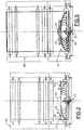
- inventions shown in Figures 1 to 12 are of the kind for opening and cutting tubular fabrics, while the ones shown in Figures 13 to 15 are only for opening tubular fabrics.
- a fabric in rope-like form 10 advances in the direction indicated by arrow A towards an untwisting device for eliminating the twist in the fabric.
- an untwisting device for eliminating the twist in the fabric.
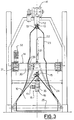
- a structure 12 Downstream of the untwisting device is a structure 12, the free end of which carries an idly mounted ring 13 through which the fabric 10 coming from the untwisting device is made to pass.
- the fabric Downstream of this unit the fabric is free until it comes to and passes through a further device 14, that will be better described further on. Then, the fabric arrives to a conventional cutter 15, of the type generally used in this kind of plant.
- a unit 16 downstream of the cutter is a unit 16 comprising a motor 17 that sends air to a scroll 19 through a pump 18.
- a tube 20 extends from the free end of the scroll 19 and is provided at its ends with a plurality of nozzles 21, 22.
- the tube is slipped inside the fabric above the cutter 15, through the device 14 and inside the above indicated free portion of fabric that is comprised between the ring 13 and the device 14.
- the nozzles blow the air the is sent by the pump 18 inside said free portion of fabric, blowing it up so as to get it to take the arrangement shown in Figures 1, 2 and 3.
- a triangular device 24 Downstream of the assembly formed by the cutter and the scroll 19 is a triangular device 24, of known kind per se. Owing to the particular solution that is proposed, the device 24 extends upwardly beyond the cutter 15 and inside the device 14, to the extent that is deemed more convenient without causing encumbrance or hindrance problems to the other devices.
- the fabric that is opened by the cutter and laid open by the triangle 24 is then delivered to rollers 25 of a foulard unit.
- the rollers deliver it to other devices known “per se”, such as expanding and centring devices 26, cloth folders, and so on.
- the device 14 consists of a belt 30 that winds over pulleys 31, one of which is rotated in reciprocating rotary motion by a motor 32.
- a set of equally spaced rollers 33 having their axes disposed substantially parallel to the plane of the belt are idly mounted on the belt.
- the belt 30 Upon rotating in both ways due to the action of the motor 32, the belt 30 causes the rollers 33 on the belt to friction horizontally the fabric 10 passing inside the belt.
- the rollers 33 make the fabric rotate in the two opposite ways with respect to its vertical direction of advancement.
- the rollers 33 are idle, they transmit irrelevant friction, or no friction at all, to the fabric moving vertically. Therefore, the fabric can maintain its vertical speed.
- oscillating rollers 34 can be fitted in a side position, in such a way that if they are rotated in the direction of arrow B they bias one side of the belt towards the other side for variating (increasing or decreasing) the width of the tubular fabric arriving to the cutter 15.
- the cutter 15 will obviously be mounted on a sledge 35 so as to allow it to slide sideways and cut automatically with the precision of the needle.
- the cutter 15 and the belt 30 are also connected so as to cooperate in directing the fabric correctly while it descends to be cut and expand out on the triangle 24.
- the triangle is advantageously slipped to a considerable extent inside the tubular fabric and above the belt 30 so as to ensure perfect expansion without causing weft distortion.
- This apparatus that provides blowing up of the tubular fabric at portion 23 by simply insufflating air inside through nozzles 21 and 22, allows to eliminate the use of a conventional basket.
- Another advantage is that the rotation of the tubular fabric upstream of the cutter is accomplished from the outside (by the rollers 33 of belt 30). Therefore, no mechanical tools or units have to be employed inside the tubular fabric, as is instead currently done when a conventional basket is used.
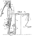
- the device 14 is formed by two pairs of helically scored rolls.
- the pair of rolls 40 that are fitted on one side have opposite handed helics scored thereon with respect to the rolls 41 located on the other side.
- Suitable motor means provide reciprocating rotary motion to the two pairs of rolls 40, 41, so as to rotate in either way the fabric that advances vertically, in the same way as this rotation was accomplished in the embodiment of Figures 1 to 3 by the belt 30 and its rollers 33.
- the pairs of rolls 40, 41 do not provide considerable friction against the vertical advancement of the fabric. This is also demonstrated by the fact that these rolls are well known in prior art and are currently used in several applications, as for example the expanding units indicated by numeral 26 in the drawings.
- FIGs 7 and 8 show a solution wherein the fabric 23 is rotated from the inside instead of the outside, as shown in the previous figures.
- the rotating device is an umbrella 50 that rotates about its own vertical axis and has arms 51 fitted with idle rollers 52 upon which the fabric slides. These rollers 52 have the same function of the rollers 33 of Figures 1-3 of the first embodiment, so their characteristics and operation no longer need to be described in detail.
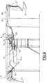
- Figure 9 shows the aforesaid apparatus, wherein the device 14 is a hybrid of the above described first two embodiments.
- the third embodiment shows that by using air to blow the fabric up and a device 14 to rotate it before it arrives to the cutter, the apparatus can be disposed horizontal instead of vertical. This arrangement involves obvious maintenance facilitations and renders the various parts of the apparatus more accessible.
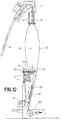
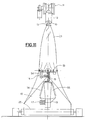
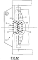
- FIGs 10 to 13 show a variant of the device 14 for rotating the fabric 23.
- This variant provides two chains or belts 42, 53 fitted with the rollers 33 already described with reference to Figures 1 to 3.
- One belt 53 is positioned at the inside of the fabric 23, while the other belt 42 is on the outside and is moved by a motor 54.
- the two belts 42 and 53 face each other for a portion along which the rollers on one belt are displaced with respect to the ones on the other belt.
- the fabric passing between the two belts in that part is rotated in either way by moving the outer belt 42.
- the latter urges also the inner belt 53 to rotate and, consequently, the fabric that is interposed there between.
- the scroll 19 can send air to a flat body 55 instead of the tube, as in the previous examples.
- the body 55 is formed by two overlapping surfaces separated by an air passage gap.
- the edges of the flat body are provided with a plurality of nozzles 56 sending the air sideways and upwards in the fabric 23, obtaining the same effect of the aforesaid tube with nozzles.
- numeral 1 indicates a frame for sustaining the apparatus of this invention in case it is only desired to open the tubular fabric.
- Numeral 23 indicates a tubular fabric in rope-like form coming from a dyeing apparatus (not shown).
- the fabric 23 advancing in the direction of arrow A is delivered to an untwisting device 11, known per se, for eliminating twistings in the tubular fabric.
- the fabric Downstream of the idle ring 13 the fabric is free of twistings, but is not expand out.
- the fabric passes through a expanding device 57 which, according to this invention, consists of a plurality of air nozzles disposed in various positions, also in opposite positions.
- the nozzles are obtained in two plates 58 that are fixed to the frame 60 and air fed through an air conduit 59 by a pump, not shown for simplicity.
- the fabric Upon passing through these two plates and being air insufflated, the fabric expands and arrives in this form to a successive centring device 14 that can be accomplished in three different embodiments herein disclosed.
- the device 11 comprises the already described belt 30 wound on pulleys 31 and provided with equally spaced idle rollers 33 having their axes substantially parallel to the belt's motion plane.
- the rollers 33 friction horizontally the fabric 23 passing in the belt.
- the fabric is rotated in the two opposite ways with respect to the vertical direction in which the fabric advances.
- the wefts are maintained rectilinear.
- the rollers 33 being idle, realise very little friction or almost no friction at all on the fabric moving vertically. Therefore, the fabric can maintain its vertical speed.
- a second embodiment of the centring device shown in the drawings makes use of two rolls 40, 41 with helically scored surfaces, of the kind disclosed in Figures 4 to 6.
- This embodiment also exploits suitable motor means (not shown) for providing reciprocating rotary motion to the two rolls 40, 41, so as to always rotate in either way the fabric as it advances vertically.
- suitable motor means not shown
- the two rolls 40, 41 do not friction the fabric considerably: as a matter of fact, similar rolls are used in the sector for other applications, for example in cloth folders or spreading devices of known kind.
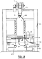
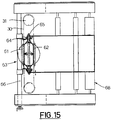
- a third embodiment of the device 14 shown in Figures 13 to 15 makes use of two rigid bars 61,62.
- This arrangement is employed for fabrics not requiring the weft to be positioned vertical.
- the two bars can have nozzles to allow air passage and be connected to the air feed of tube 59 (not shown).
- This provides further expanding of the fabric and keeps it always contacting the two bars, so that the fabric is well stretched out when it arrives to the expanding and tensioning assembly 63 located downstream of the centring device.
- the tensioning assembly 63 is common to all three of the embodiments of the apparatus of the drawings, and it is composed by two idle wheels 64 that cooperate with two pairs of V shaped walls 65 between which the fabric passes. Said walls are movable along an axle 66 connected to the frame for following the different shapes of the fabric.
- the apparatus of this invention is fitted with a roll 67 for pulling the fabric and make it pass in a cloth folding assembly 68 to be stored.
Landscapes
- Engineering & Computer Science (AREA)
- Textile Engineering (AREA)
- Treatment Of Fiber Materials (AREA)
Applications Claiming Priority (4)
| Application Number | Priority Date | Filing Date | Title |
|---|---|---|---|
| ITTO921038A IT1258129B (it) | 1992-12-24 | 1992-12-24 | Apparecchiatura per l'allargamento di maglie tubolari in corda. |
| ITTO921038 | 1992-12-24 | ||
| ITTO921037 | 1992-12-24 | ||
| ITTO921037A IT1258128B (it) | 1992-12-24 | 1992-12-24 | Apparecchiatura per il taglio di maglie tubolari. |
Publications (1)
| Publication Number | Publication Date |
|---|---|
| EP0603645A1 true EP0603645A1 (de) | 1994-06-29 |
Family
ID=26332218
Family Applications (1)
| Application Number | Title | Priority Date | Filing Date |
|---|---|---|---|
| EP93119759A Withdrawn EP0603645A1 (de) | 1992-12-24 | 1993-12-08 | Vorrichtung zum Öffnen und Drehen von Schlauchwaren in Strängform |
Country Status (1)
| Country | Link |
|---|---|
| EP (1) | EP0603645A1 (de) |
Cited By (7)
| Publication number | Priority date | Publication date | Assignee | Title |
|---|---|---|---|---|
| EP0708195A1 (de) * | 1994-10-21 | 1996-04-24 | BIANCO S.p.A. | Vorrichtung zum Zentrieren eines Schlauchförmigen Gewebes |
| EP1970484A1 (de) * | 2007-03-13 | 2008-09-17 | Corino Macchine S.r.l. | Mehrzweckseilöffnungsvorrichtung |
| CN101476224B (zh) * | 2008-11-20 | 2011-05-11 | 天津工业大学 | 一种长丝退捻装置 |
| ITTO20100075A1 (it) * | 2010-02-03 | 2011-08-04 | Bianco Spa | Braccio di un telaio per il posizionamento angolare di un tessuto tubolare, e telaio provvisto di tale braccio |
| ITTO20110069A1 (it) * | 2011-01-26 | 2012-07-27 | Bianco Spa | Gruppo di torsione per ruotare un tessuto tubolare |
| CN108893968A (zh) * | 2018-09-28 | 2018-11-27 | 浙江三德纺织服饰有限公司 | 一种成像追踪剖幅系统及其使用方法 |
| CN115287853A (zh) * | 2022-08-24 | 2022-11-04 | 佛山市科伦机电设备有限公司 | 一种印染用绳状混布的退捻分布机 |
Citations (7)
| Publication number | Priority date | Publication date | Assignee | Title |
|---|---|---|---|---|
| DE2254371A1 (de) * | 1972-11-07 | 1974-05-30 | Erhardt & Leimer Kg | Vorrichtung zum oeffnen schlauchfoermiger wirkware |
| US3813862A (en) * | 1972-03-31 | 1974-06-04 | I Tsuchida | Apparatus for detecting and correcting torsion of travelling fabric |
| FR2394632A1 (fr) * | 1977-06-15 | 1979-01-12 | Bassani Mariano | Dispositif pour le detordage des tissus mis en torsade |
| DE2844663A1 (de) * | 1978-10-13 | 1980-04-24 | Heliot Maurice Ets | Verfahren und vorrichtung zur herstellung oder bearbeitung von schlauchartigen erzeugnissen |
| GB2070660A (en) * | 1980-02-29 | 1981-09-09 | Bianco Snc Off | Apparatus for cutting and opening tubular knitted fabric |
| FR2567164A1 (fr) * | 1984-07-04 | 1986-01-10 | Domisse | Machine de detorsion et d'ouverture des tricots. |
| EP0264677A1 (de) * | 1986-10-16 | 1988-04-27 | Brückner Apparatebau GmbH | Verfahren und Vorrichtung zur Nassbehandlung von textiler Schlauchware |
-
1993
- 1993-12-08 EP EP93119759A patent/EP0603645A1/de not_active Withdrawn
Patent Citations (7)
| Publication number | Priority date | Publication date | Assignee | Title |
|---|---|---|---|---|
| US3813862A (en) * | 1972-03-31 | 1974-06-04 | I Tsuchida | Apparatus for detecting and correcting torsion of travelling fabric |
| DE2254371A1 (de) * | 1972-11-07 | 1974-05-30 | Erhardt & Leimer Kg | Vorrichtung zum oeffnen schlauchfoermiger wirkware |
| FR2394632A1 (fr) * | 1977-06-15 | 1979-01-12 | Bassani Mariano | Dispositif pour le detordage des tissus mis en torsade |
| DE2844663A1 (de) * | 1978-10-13 | 1980-04-24 | Heliot Maurice Ets | Verfahren und vorrichtung zur herstellung oder bearbeitung von schlauchartigen erzeugnissen |
| GB2070660A (en) * | 1980-02-29 | 1981-09-09 | Bianco Snc Off | Apparatus for cutting and opening tubular knitted fabric |
| FR2567164A1 (fr) * | 1984-07-04 | 1986-01-10 | Domisse | Machine de detorsion et d'ouverture des tricots. |
| EP0264677A1 (de) * | 1986-10-16 | 1988-04-27 | Brückner Apparatebau GmbH | Verfahren und Vorrichtung zur Nassbehandlung von textiler Schlauchware |
Cited By (9)
| Publication number | Priority date | Publication date | Assignee | Title |
|---|---|---|---|---|
| EP0708195A1 (de) * | 1994-10-21 | 1996-04-24 | BIANCO S.p.A. | Vorrichtung zum Zentrieren eines Schlauchförmigen Gewebes |
| US5598614A (en) * | 1994-10-21 | 1997-02-04 | Bianco S.P.A. | Device for centering a tubular fabric |
| EP1970484A1 (de) * | 2007-03-13 | 2008-09-17 | Corino Macchine S.r.l. | Mehrzweckseilöffnungsvorrichtung |
| CN101476224B (zh) * | 2008-11-20 | 2011-05-11 | 天津工业大学 | 一种长丝退捻装置 |
| ITTO20100075A1 (it) * | 2010-02-03 | 2011-08-04 | Bianco Spa | Braccio di un telaio per il posizionamento angolare di un tessuto tubolare, e telaio provvisto di tale braccio |
| ITTO20110069A1 (it) * | 2011-01-26 | 2012-07-27 | Bianco Spa | Gruppo di torsione per ruotare un tessuto tubolare |
| CN108893968A (zh) * | 2018-09-28 | 2018-11-27 | 浙江三德纺织服饰有限公司 | 一种成像追踪剖幅系统及其使用方法 |
| CN108893968B (zh) * | 2018-09-28 | 2024-04-19 | 浙江三德纺织服饰有限公司 | 一种成像追踪剖幅系统及其使用方法 |
| CN115287853A (zh) * | 2022-08-24 | 2022-11-04 | 佛山市科伦机电设备有限公司 | 一种印染用绳状混布的退捻分布机 |
Similar Documents
| Publication | Publication Date | Title |
|---|---|---|
| US4545544A (en) | Fabric handling apparatus and method | |
| US5103621A (en) | Film spreading device for use in wrapping apparatus | |
| US5826314A (en) | Device for transversely stretching web | |
| US5779232A (en) | Method and device for the production of a longitudinal fold | |
| CN218024507U (zh) | 一种纵向弹性复合无纺布生产装置 | |
| US3652080A (en) | Apparatus for cutting and folding flexible sheet material | |
| US4053151A (en) | High speed fabric folder | |
| US3955251A (en) | Fabric spreading and stretching apparatus | |
| US5598614A (en) | Device for centering a tubular fabric | |
| US3218829A (en) | Spreader for knit fabrics for use on circular knitting machines | |
| US4914995A (en) | Rotary cutting apparatus | |
| US3552248A (en) | Tenter means for fabrics and the like | |
| JPS6087151A (ja) | 平らな帯状材料または帯状薄片を巻くための装置 | |
| DE2509506C2 (de) | Vorrichtung zum maschinellen Falten und Nähen der Längskanten einer fortlaufenden Gewebebahn | |
| US3401584A (en) | Method and apparatus for slitting and opening tubular knitted fabric | |
| US3345232A (en) | Method and apparatus for making criss-cross material | |
| US5529470A (en) | Apparatus for flattening a blown foil tube of thermoplastic synthetic resin | |
| EP1258555A1 (de) | Vorrichtung zum breithalten von Warenbahnen | |
| CN103072843B (zh) | 一种编织袋裁切防皱机构 | |
| US4734088A (en) | Apparatus for making bags | |
| US3604648A (en) | Continuous web handling and winding apparatus | |
| CN110678316A (zh) | 用于扫掠转子叶片的单向纤维预制件的连续剪切成型的设备 | |
| CN207451190U (zh) | 一种连续高效打卷机 | |
| JPH03167369A (ja) | ホース状製品の丸形幅出機 | |
| US3551969A (en) | Apparatus for slitting,opening and processing tubular knitted fabric |
Legal Events
| Date | Code | Title | Description |
|---|---|---|---|
| PUAI | Public reference made under article 153(3) epc to a published international application that has entered the european phase |
Free format text: ORIGINAL CODE: 0009012 |
|
| AK | Designated contracting states |
Kind code of ref document: A1 Designated state(s): DE ES FR GB IT |
|
| 17P | Request for examination filed |
Effective date: 19941109 |
|
| 17Q | First examination report despatched |
Effective date: 19961002 |
|
| STAA | Information on the status of an ep patent application or granted ep patent |
Free format text: STATUS: THE APPLICATION IS DEEMED TO BE WITHDRAWN |
|
| 18D | Application deemed to be withdrawn |
Effective date: 19970221 |