EP0603655A2 - Strombegrenzender Solenoid-Treiber - Google Patents
Strombegrenzender Solenoid-Treiber Download PDFInfo
- Publication number
- EP0603655A2 EP0603655A2 EP93119820A EP93119820A EP0603655A2 EP 0603655 A2 EP0603655 A2 EP 0603655A2 EP 93119820 A EP93119820 A EP 93119820A EP 93119820 A EP93119820 A EP 93119820A EP 0603655 A2 EP0603655 A2 EP 0603655A2
- Authority
- EP
- European Patent Office
- Prior art keywords
- solenoid
- current
- signal
- input
- output
- Prior art date
- Legal status (The legal status is an assumption and is not a legal conclusion. Google has not performed a legal analysis and makes no representation as to the accuracy of the status listed.)
- Granted
Links
- 239000003990 capacitor Substances 0.000 claims description 12
- 238000000034 method Methods 0.000 claims description 9
- 238000012544 monitoring process Methods 0.000 claims description 5
- 238000002955 isolation Methods 0.000 claims description 4
- 238000001514 detection method Methods 0.000 abstract description 2
- 238000012360 testing method Methods 0.000 description 5
- 230000007423 decrease Effects 0.000 description 3
- 238000013461 design Methods 0.000 description 2
- 239000004065 semiconductor Substances 0.000 description 2
- 238000013459 approach Methods 0.000 description 1
- 150000001875 compounds Chemical class 0.000 description 1
- 230000001934 delay Effects 0.000 description 1
- 238000003745 diagnosis Methods 0.000 description 1
- 230000005669 field effect Effects 0.000 description 1
- 230000001939 inductive effect Effects 0.000 description 1
- 238000012423 maintenance Methods 0.000 description 1
- 238000013024 troubleshooting Methods 0.000 description 1
Images


Classifications
-
- G—PHYSICS
- G05—CONTROLLING; REGULATING
- G05F—SYSTEMS FOR REGULATING ELECTRIC OR MAGNETIC VARIABLES
- G05F1/00—Automatic systems in which deviations of an electric quantity from one or more predetermined values are detected at the output of the system and fed back to a device within the system to restore the detected quantity to its predetermined value or values, i.e. retroactive systems
- G05F1/10—Regulating voltage or current
-
- B—PERFORMING OPERATIONS; TRANSPORTING
- B60—VEHICLES IN GENERAL
- B60L—PROPULSION OF ELECTRICALLY-PROPELLED VEHICLES; SUPPLYING ELECTRIC POWER FOR AUXILIARY EQUIPMENT OF ELECTRICALLY-PROPELLED VEHICLES; ELECTRODYNAMIC BRAKE SYSTEMS FOR VEHICLES IN GENERAL; MAGNETIC SUSPENSION OR LEVITATION FOR VEHICLES; MONITORING OPERATING VARIABLES OF ELECTRICALLY-PROPELLED VEHICLES; ELECTRIC SAFETY DEVICES FOR ELECTRICALLY-PROPELLED VEHICLES
- B60L7/00—Electrodynamic brake systems for vehicles in general
- B60L7/003—Dynamic electric braking by short circuiting the motor
-
- H—ELECTRICITY
- H03—ELECTRONIC CIRCUITRY
- H03K—PULSE TECHNIQUE
- H03K17/00—Electronic switching or gating, i.e. not by contact-making and –breaking
- H03K17/08—Modifications for protecting switching circuit against overcurrent or overvoltage
- H03K17/082—Modifications for protecting switching circuit against overcurrent or overvoltage by feedback from the output to the control circuit
- H03K17/0826—Modifications for protecting switching circuit against overcurrent or overvoltage by feedback from the output to the control circuit in bipolar transistor switches
-
- H—ELECTRICITY
- H03—ELECTRONIC CIRCUITRY
- H03K—PULSE TECHNIQUE
- H03K17/00—Electronic switching or gating, i.e. not by contact-making and –breaking
- H03K17/51—Electronic switching or gating, i.e. not by contact-making and –breaking characterised by the components used
- H03K17/56—Electronic switching or gating, i.e. not by contact-making and –breaking characterised by the components used by the use, as active elements, of semiconductor devices
- H03K17/60—Electronic switching or gating, i.e. not by contact-making and –breaking characterised by the components used by the use, as active elements, of semiconductor devices the devices being bipolar transistors
- H03K17/64—Electronic switching or gating, i.e. not by contact-making and –breaking characterised by the components used by the use, as active elements, of semiconductor devices the devices being bipolar transistors having inductive loads
Definitions
- This invention relates to apparatus and methods for driving and limiting the current of electric solenoids.
- Electric solenoids have been used in automotive applications for some time, and a variety of control systems have been designed to control their operating currents.
- One reason for the variety of control systems is the variation of system source voltages and solenoid characteristics. Automotive applications typically involve an interface of a computer operating at 5 volts to a solenoid powered by a 12-volt or 24-volt power supply. The resistance of each solenoid must be relatively low to ensure that, even with the lowest reasonable system voltage applied, adequate current is developed to effectively attract an associated armature.
- a relatively high system voltage is applied to a solenoid having a low resistance, however, a higher than required current is developed; and the solenoid is forced to dissipate the excess energy as heat.
- the voltage applied to a solenoid having a resistance of 3 ohms varies between 7 and 30 volts, the power varies between 16 and 300 watts.
- Producing a solenoid that is simultaneously capable of being actuated by a low system voltage and capable of dissipating the excess energy generated by a high system voltage is difficult and costly, and the resulting solenoid is likely to be impractically large for many planned applications.
- a common method of controlling current applied to a solenoid is that of using a linear control system.
- a solenoid driver in the control system absorbs excess energy not required to drive the solenoid.
- a disadvantage of such a system is that it supplies more energy to the solenoid driver and to the solenoid than is needed, for example, with a switch-mode control system.
- High-side solenoid drivers that is, solenoid drivers disposed on the power supply side of a solenoid
- solenoid control systems require the attendant use of level shifting circuitry, however, which adds cost and complexity.
- level shifting circuitry As the circuitry becomes more sophisticated, the cost and complexity of associated interface circuitry also increases.
- semiconductors for example, NPN bipolar transistors and N-channel field-effect transistors
- semiconductors used in control systems using low-side solenoid drivers are available in a wider selection with better characteristics at lower cost than are those used in high-side solenoid drivers.
- An object of the present invention is to provide an improved, relatively uncomplicated, relatively inexpensive, switch-mode, solenoid driver and method for accurately controlling current applied to an electric solenoid and to minimize power dissipated by the solenoid and its associated driver.
- Another object of the present invention is to selectively limit current applied to a solenoid.
- Still another object of the present invention is to provide an improved apparatus and method for accurately controlling current applied to one of a number of electric solenoids.
- Yet another object of the present invention is to provide a solenoid driver capable of supplying an actuating current to a solenoid during the armature attracting phase and supplying a reduced holding current after the armature has been attracted.
- a feature of the present invention is the protection provided the solenoid driver against damage resulting from being shorted to the source of electric current.
- Another feature of the present invention is means provided for fault detection.
- a first embodiment of the present invention includes a low-side, switch-mode, solenoid driver for controlling electric current from a system power supply, or source of electric current, to actuate and hold actuated an electric solenoid.
- the current is applied in response to a solenoid control signal and with respect to a predetermined current reference signal.
- a switching transistor is used to rapidly switch current applied to the solenoid on and off to generate a pulsed current.
- Current is switched on until a signal representative of current flowing through the solenoid increases to an upper limit, whereupon it is switched off. The current remains off until the signal decreases to a lower limit, whereupon the current is again switched on.
- Solenoid inductance integrates the resulting pulsed current into a substantially steady-state current.
- the solenoid driver also includes a detecting circuit for detecting current flow through the solenoid and generating in response thereto a peak signal representative of the amount of current flowing therethrough.
- the detecting circuit includes a current sensing resistor connected in series with the solenoid and the switching transistor. Since the sensing resistor is connected in series with the solenoid, the amount of voltage developed across the resistor is representative of the amount of current flowing through the solenoid.
- the voltage developed across the sensing resistor is applied to a differential amplifier having a peak detector connected to its output to develop a peak signal representative of the peak current flowing through the solenoid.
- the peak signal is input, with the predetermined current reference signal, to a comparator; and a deviation signal is generated that is representative of the difference therebetween.
- the deviation signal is input, with the solenoid control signal, to a logical NOR gate; and a solenoid current control signal is generated that controls the switching transistor.
- the present invention also includes a microprocessing unit, one function of which is to generate a current set point signal.
- a current set point circuit receives the current set point signal from an output of the microprocessing unit and generates in response thereto the current reference signal.
- An analog-to-digital converter is connected between the peak detector and an input of the microprocessing unit for converting the analog peak signal to a digital monitoring signal, representative of the amount of current flowing through the solenoid, to be used by the microprocessing unit to diagnose system faults and log errors to facilitate trouble shooting.
- a second embodiment of the present invention includes a low-side, switch-mode, solenoid driver for controlling electric current from a system power supply, or source of electric current, to actuate and hold actuated one of a plurality of electric solenoids.
- the solenoid driver of the second embodiment functions in a manner that is similar to that of the first but additionally includes a set of Darlington amplifiers and associated circuitry for each solenoid. It also includes a logical NOR gate for each solenoid, each of the NOR gates being input with a separate solenoid control signal to select a specific one of the plurality of solenoids.
- a third embodiment of the present invention includes a high-side, switch-mode, solenoid driver for controlling electric current from a system power supply, or source of electric current, to actuate and hold actuated an electric solenoid.
- the solenoid driver of the third embodiment principally differs from that of the first in that the switching transistor is disposed between the source of electric current and the solenoid, the solenoid driver therefore being referred to as a high-side solenoid driver.
- the solenoid driver functions in a manner similar to that of the first embodiment but additionally includes a current control transistor that receives the solenoid current control signal and controls the switching transistor in response thereto.
- Solenoid drivers may be divided into two general categories, high-side solenoid drivers and low-side solenoid drivers.
- a schematic illustration of a simplified high-side solenoid driver is shown by FIG. 1 of the drawings.
- a high-side solenoid driver generally indicated by the reference numeral 10 , is typically disposed between a system power supply, or source of electric current 12 , and an associated solenoid 14 being controlled thereby.
- the high-side solenoid driver also includes a power supply 16 , a microprocessing unit 18 , a buffer 20 and a switching transistor 22 .
- FIG. 2 of the drawings A schematic illustration of a simplified low-side solenoid driver 10 is shown by FIG. 2 of the drawings.
- a low-side solenoid driver generally indicated by the reference numeral 24 , is typically disposed between a solenoid 14 being controlled thereby and ground.
- the low-side solenoid driver also includes a power supply 16 , a microprocessing unit 18 , a buffer 20 and a switching transistor 26 .
- Low-side solenoid drivers offer the advantages of having available for use therein a wider selection of semiconductor devices with more desirable characteristics and at a lower cost than do high-side solenoid drivers. Advantage has been taken of these factors in the design of the solenoid drivers in the first two of three disclosed embodiments of the present invention.
- a solenoid must be designed to have sufficient magnetomotive force, or ampere turns, to ensure the attraction of an associated armature. Once the armature has been attracted, however, magnetic reluctance within the magnetic circuit is reduced; and a lower current can be used to hold the armature in its attracted position. If a control circuit is used that reduces current flowing through the solenoid once its armature has been attracted, the amount of excess energy the solenoid must dissipate is also reduced; and the size, weight and cost of the solenoid can be reduced accordingly. Since the holding current is lower than the actuation current, the armature release time is shortened. The use of this type of control circuit can significantly improve the performance-versus-cost ratio of the solenoid and has been incorporated into the solenoid driver control circuit of the three embodiments of the present invention.
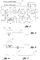
- FIG. 3 of the drawings Shown is a schematic depicting a low-side, switch-mode, solenoid driver, generally indicated by the reference numeral 28 , for controlling electric current to actuate and hold actuated an electric solenoid 14 .
- the control of current applied to the solenoid 14 is effectively a function of three factors, a solenoid control signal 30 , a current reference signal 32 and current measured flowing through the solenoid 14 .
- the solenoid control signal 30 indicates that the solenoid 14 is to be actuated.
- the current reference signal 32 provides a reference against which a signal representative of the actual current flowing through the solenoid 14 is compared, the circuit controlling the application of current to the solenoid being opened and closed as the current flowing through the solenoid 14 respectively exceeds and falls below predetermined limits.
- a switching transistor 34 or switching means, having a collector 33 connected to the solenoid 14 , a base 35 and an emitter 37 connected to ground through a current sensing resistor 36 is used to rapidly switch the current on and off, resulting in a pulsed current being applied to the solenoid 14 .
- Solenoid inductance integrates the resulting pulsed current into a substantially steady-state current.
- a field decay protection diode 39 is connected between the collector 33 and the emitter 37 of the switching transistor 34 to provide protection therefor.
- the current reference signal 32 is set to provide sufficient current for a predetermined "pull-in" period to actuate the solenoid 14 and attract an associated armature (not shown).
- the magnetic reluctance of the solenoid 14 decreases; and the current required to hold the attracted armature in position also decreases. At this time, the current reference signal 32 is reduced to the level required to maintain the armature in its attracted position.
- the current flowing through the solenoid 14 is monitored by measuring the voltage across a sensing resistor 36 connected in series with the solenoid 14 and the switching transistor 34 . Since the sensing resistor 36 is in series with the solenoid 14 , the amount of voltage developed across the sensing resistor 36 is representative of the amount of current flowing through the solenoid 14 .
- the sensing resistor 36 is part of a detecting circuit, or detecting means, generally indicated by the reference numeral 38 , that also includes a differential amplifier 40 and a peak detector, generally indicated by the reference numeral 42 .
- the differential amplifier 40 has an inverting input 44 , a noninverting input 46 and an output 48 .
- the peak detector 42 includes a peak detector capacitor 50 , a peak detector bleed resistor 51 and a peak detector diode 52 having a cathode 54 and an anode 56 .
- the anode 56 of the peak detector diode 52 is connected to the output 48 of the differential amplifier 40 ; and the peak detector capacitor 50 and the peak detector bleed resistor 51 are connected between the cathode 54 of the peak detector diode 52 and ground, the connection between the peak detector capacitor 50 and the cathode 54 of the peak detector diode 52 effectively being the output 58 of the peak detector 42 .
- the emitter 37 of the switching transistor 34 is also connected through a differential amplifier input resistor 47 to the noninverting input 46 of the differential amplifier 40 , and a first differential amplifier gain resistor 60 is connected between the inverting input 44 of the differential amplifier 40 and ground.
- a second differential amplifier gain resistor 62 is connected between the inverting input 44 of the differential amplifier 40 and the cathode 54 of the peak detector diode 52 .
- the solenoid driver 28 could have been designed with the current sensing resistor 36 disposed in the collector circuit of the switching transistor 34 so that current would flow through the current sensing resistor 36 whether the switching transistor 34 is on or off. This would simplify the monitoring of solenoid current flow; but, since the voltage read across the current sensing resistor 36 would have to be level shifted, the differential amplifier 40 would have to be more complex and costly. In one potential solution to this problem, the voltage could be divided to reduce it to a level within an acceptable range of the differential amplifier 40 and then amplified; but this approach is complicated and expensive. Another potential solution would be to use a Norton amplifier; but, due to the variable characteristics of available amplifiers, this has not proved to be practical.
- the peak detector 42 can have a decay rate that mimics the decay rate of current in the solenoid 14 .
- the ratio of the resistances of the first and second differential amplifier gain resistors ( 60 and 62 respectively) determines the gain of the differential amplifier 40
- the absolute value of the resistances of the first and second differential amplifier gain resistors ( 60 and 62 respectively) determines the discharge rate of the peak detector capacitor 50 .
- the amplifier gain A V is given by the following equation.
- a peak detector discharge resistor (not shown) may be placed across the peak detector capacitor; but, as shown in the circuit of FIG. 3 , it may be eliminated by properly selecting the resistance values of the first and second differential amplifier gain resistors ( 60 and 62 respectively) according to equations (1) and (2).
- the peak detector 42 additionally provides the solenoid driver 28 with protection against damage resulting from being shorted to the source of electric current 12 . If the solenoid driver 28 should become shorted to the source of electric current 12 , a current having an instantaneous level far exceeding that represented by the current reference signal 32 is forced through the current sensing resistor 36 . Accordingly, the differential amplifier 40 pumps the output voltage of the peak detector 42 to a maximum.
- the rise rate of current being driven through a normal inductive load is slowed as a function of the time constant of the load, the time constant being the ratio (L/R) of load inductance to resistance.
- An associated control circuit is therefore capable of maintaining the current within prescribed limits. Under short circuit conditions, however, the rise rate is nearly instantaneous; and associated control circuit components are incapable of responding rapidly enough to maintain the current within the limits. Under such conditions the current is limited only by the system voltage, or source of electrical current, the resistance of the current sense resistor 36 and the gain of the output device.
- the solenoid driver 28 of the first embodiment once the control circuit does respond and the switching transistor 34 is switched off, it requires a significant amount of time for the peak detector to respond sufficiently for the switching transistor 34 to be switched on again.
- the current flow would have a predominantly low level punctuated by short spikes of high level current. Power dissipation by the solenoid driver 28 is thus minimal, and the latter is capable of withstanding a continuous short to the source of electric current.
- the peak detector 42 must have a range of operation substantially greater than normal.
- a typical example would include a solenoid driver 28 wherein a current of 1 ampere flowing through the current sensing resistor 36 would be represented by a voltage of 1 volt appearing at the output 58 of the peak detector 42 .
- an armature attracting, or pull-in, current of 2 amperes would be represented by a voltage of 2 volts.
- a short circuit would drive the output 58 of the peak detector 42 to a significantly higher level of 3.5 or 4 volts.
- a substantial amount of time would be required for the voltage to decay from this level to that of 1 or 2 volts, thus providing a low duty cycle during a short circuit.
- Another requirement to be satisfied includes keeping the impedance being driven by the differential amplifier 40 sufficiently high so that the differential amplifier 40 is capable of responding quickly.
- a comparator 64 or comparing means, having an inverting input 66 , a noninverting input 68 and an output 70 .
- a first comparator gain resistor 72 is connected between the noninverting input 68 of the comparator 64 and the output 58 of the peak detector 42 .
- a second comparator gain resistor 74 is connected between the noninverting input 68 of the comparator 64 and the output 70 of the comparator 64 .
- a logical NOR gate 76 or logical gating means, having a control input 78 , a reference input 80 and an output 82 is also included. Its control input 78 receives the solenoid control signal 30 , and its reference input 80 is connected to the output 70 of the comparator 64 .
- the output 82 of the logical NOR gate 76 is connected to the base 35 of the switching transistor 34 .
- the resulting voltage developed across the current sensing resistor 36 is applied to the noninverting input 46 of the differential amplifier 40 .
- the peak detector 42 connected to the output 48 of the differential amplifier 40 develops a peak signal representative of the peak current flowing through the solenoid 14 .
- the peak signal is input to the noninverting input 68 of the comparator 64 , the predetermined current reference signal 32 is input to the inverting input 66 thereof, and a deviation signal is generated that is representative of the difference therebetween.
- the deviation signal is input, with the solenoid control signal 30 , to the logical NOR gate 76 ; and a solenoid current control signal is generated that is applied to and that controls the switching transistor 34 .
- the solenoid current control signal switches the switching transistor 34 off when the solenoid current is determined to have exceeded a predetermined upper limit and switches the switching transistor 34 on, provided the solenoid control signal 30 is still present, when the solenoid current is determined to have fallen below a predetermined lower limit.
- a flyback diode 84 is also included in the first disclosed embodiment.
- the flyback diode 84 is connected across the solenoid 14 to discharge the solenoid 14 .
- the flyback diode 84 has a cathode 86 and an anode 88 , the cathode 86 being connected to the source of electric current 12 through a flyback resistor 90 to enhance turn off properties of the circuit, the flyback resistor 90 allowing the solenoid 14 to discharge more rapidly than it charges.
- the first disclosed embodiment also includes a microprocessing unit 18 , a current set point circuit, generally indicated by the reference numeral 92 , and an analog-to-digital converter 94 .
- the current set point circuit 92 is connected between an output 96 of the microprocessing unit 18 and the inverting input 66 of the comparator 64
- the analog-to-digital converter 94 is connected between the output 58 of the peak detector 42 and an input 98 of the microprocessing unit 18 .
- the current set point circuit 92 includes a first set point resistor 100 connected between the output 96 of the microprocessing unit 18 and the inverting input 66 of the comparator 64 , a second set point resistor 102 connected between the inverting input 66 of the comparator 64 and a positive source of voltage, a third set point resistor 104 connected between the inverting input 66 of the comparator 64 and ground, and a set point capacitor 106 connected between the inverting input 66 of the comparator 64 and ground.
- One function of the microprocessing unit 18 is to generate a current set point signal.
- the latter has an initial amplitude that is maintained for a predetermined "pull-in" period, the amplitude then being reduced during a subsequent period.
- the current set point circuit 92 receives the current set point signal from the microprocessing unit 18 and generates in response thereto the current reference signal 32 .
- FIG. 4 of the drawings is a graphic representation of the current reference signal 32 , generally indicated by the reference numeral 32 .
- the current reference signal 32 Being responsive to the current set point signal, the current reference signal 32 has a corresponding initial amplitude, illustrated by an initial portion 108 , such that solenoid current generated as a result thereof is capable of attracting the solenoid armature.
- the current reference signal 32 also has a corresponding reduced amplitude, illustrated by a subsequent portion 110 , during the subsequent period such that the current applied to the solenoid is capable of maintaining the armature in its attracted position.
- the amplitude and duration of the initial portion 108 is representative of the armature attracting, or pull-in, current and is a function of system voltage.
- FIG. 5 of the drawings is a graphic representation of a typical switch-mode current waveform. Generally illustrated are the current levels flowing through the solenoid during the pull-in time, that is, the period during which the associated solenoid armature is being initially attracted, and during the hold time, that is, the period during which the armature is being held in its attracted position.
- FIG. 6 is a graphic representation of a magnified portion of the switch-mode current waveform of Figure 5 , the portion being indicated by a circle 6 .
- the waveform shown by FIG. 6 reflects the solenoid current as it varies between its predetermined upper and lower limits.
- the period and amplitude of the solenoid current illustrated are a function of comparator hysteresis and circuit delays.
- Another function of the microprocessing unit 18 (FIG. 3 ) is to provide means for monitoring solenoid current and to log any anomalies to facilitate the diagnosis of system problems. It is for this reason that the output 58 of the peak detector 42 is connected to the microprocessing unit 18 through the analog-to-digital converter 94 .
- the analog-to-digital converter 94 converts the analog peak signal to a digital monitoring signal to be input to the microprocessing unit 18 .
- the anomaly can be logged; and, if desired, the solenoid driver 28 can be switched off.
- a current detected as being below a predetermined level might indicate that the solenoid 14 is disconnected or open or that an output pin is shorted to ground. Again, appropriate precautionary or maintenance action can be taken and the anomalies logged.
- a method for testing a solenoid used in such an application includes applying a series of short test pulses 112 , such as graphically represented by FIG. 7 of the drawings, to the solenoid.
- the width of the pulses ranges between 1/2 and 2 milliseconds, the period between pulses ranges between 60 and 100 milliseconds and the pulse amplitude ranges between 300 and 500 milliamperes.
- the signal aspects vary depending on the characteristics of the solenoid, but a typically preferred signal has a pulse width of 1 millisecond and an amplitude of 400 milliamperes, the period between pulses being 80 milliseconds.
- the current sensed by the current sensing resistor 36 (FIG. 3 ) is measured.
- the pulses used for testing are too short to cause a response by the solenoid 14 , typical response times of which range between 5 and 7 milliseconds.
- the pulses 112 are, however, long enough to generate a measurable current flowing through the solenoid 14 ; and the current measured must be within a predetermined range or an error is logged.
- FIG. 8 of the drawings Shown is a low-side, switch-mode, solenoid driver, generally indicated by the reference numeral 114 , for controlling electric current to one of a number of electronic solenoids 14 .
- the solenoid driver 114 is similar to that 28 of the first embodiment except that the logical gating means includes, for each solenoid 14 , a logical NOR gate 76 and that the switching means includes, for each solenoid 14 , a Darlington amplifier 116 .
- a Darlington amplifier is basically a transistor circuit including a driver transistor 118 and an output transistor 120 the collectors of which are connected together, the emitter of the driver transistor 118 being directly connected to the base of the output transistor 120 so that the emitter current of the driver transistor 118 equals the base current of the output transistor 120 .
- the circuit effectively functions as a compound transistor having one base terminal 122 , one collector terminal 124 and one emitter terminal 126 .
- Each of the Darlington amplifiers 116 shown also includes a field decay protection diode 128 connected between the common collector and the emitter of the output transistor 120 .
- Each of the number of solenoids 14 is connected between the source of electric current 12 and the collector terminal 124 of its associated Darlington amplifier 116 .
- a base resistor 130 is connected between the base terminal 122 of each Darlington amplifier 116 and ground, and a switching capacitor 132 is connected between the collector terminal 124 of each Darlington amplifier 116 and ground.
- the base terminal 122 of each Darlington amplifier 116 is also connected to the output 82 of one of the NOR gates 76 .
- a flyback diode 134 and a flyback resistor 136 are connected in series across each solenoid 14 .
- the detecting circuit, or detecting means, generally indicated by the reference numeral 138 is also similar to that 38 in the first embodiment except for the addition of an input resistor 146 connecting the noninverting input 46 of the differential amplifier 40 to the emitter terminal 126 of each of the Darlington amplifiers 116 and an input capacitor 148 connected between the noninverting input 46 of the differential amplifier 40 and ground.
- the comparator 64 or comparing means, of the second embodiment additionally includes a comparator output resistor 150 connected between the output 70 of the comparator 64 and a source of positive voltage.
- a separate solenoid control signal 30 is input to each NOR gate 76 to select a particular solenoid 14 .
- the solenoid control signal 30 enables one half of the NOR gate 76 associated with the selected solenoid 14 . With this signal 30 present, whenever the deviation signal generated by the comparator 64 indicates that the current flowing through the solenoid 14 is below a lower limit, the Darlington amplifier 116 associated with the selected solenoid 14 is switched to apply current to the solenoid 14 .
- the Darlington amplifier 116 associated therewith is switched to interrupt the flow of current thereto.
- the operation of the solenoid driver 114 is similar to that 28 of the first embodiment.
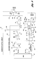
- FIG. 9 of the drawings The third disclosed embodiment of the present invention is illustrated by FIG. 9 of the drawings. It is similar to the solenoid driver 28 of the first embodiment in that it controls electric current from a system power supply, or source of electric current 12 , to actuate and hold actuated an electric solenoid 14. It differs basically in being a high-side solenoid driver, generally indicated by the reference numeral 151 , rather than a low-side solenoid driver.
- the low-side and the high-side solenoid drivers use many similar components but arrange a number of them somewhat differently.
- the primary difference is that the high-side solenoid driver is disposed between the source of electric current 12 and the solenoid 14 rather than being disposed between the solenoid 14 and ground, as is the case with a low-side solenoid driver.
- the switching means of the high-side solenoid driver includes a switching transistor 152 having a collector 154 , a base 156 and an emitter 158 and a switching diode 160 having a cathode 162 connected to the emitter 158 of the switching transistor 152 and to the source of electric current 12 and an anode 164 connected to the collector 154 of the switching transistor 152 .
- the switching means also includes a current control transistor 166 having a collector 168 , a base 170 and an emitter 172 .
- a first switching resistor 174 is connected between the source of electric current 12 and the base 156 of the switching transistor 152
- a second switching resistor 176 is connected between the base 156 of the switching transistor 152 and the collector 168 of the current control transistor 166 .
- the emitter 172 of the current control transistor 166 is connected to ground, and the base 170 thereof is connected to the output 82 of the NOR gate 76 .
- the detecting circuit, or detecting means, generally indicated by the reference numeral 180 is also similar to that 38 in the first embodiment except that the solenoid 14 is connected between the current sensing resistor 36 and ground. Additional components include a switching capacitor 182 connected across the solenoid 14 , and a flyback diode 184 having an anode 186 connected to ground and a cathode 188 connected across the series circuit of the current sensing resistor 36 and the solenoid 14 .
- the high-side solenoid driver 151 also includes an isolation diode 196 having an anode 198 connected to the collector 154 of the switching transistor 152 and a cathode 200 connected to the cathode 188 of the flyback diode 184 .
- That 64 of the third embodiment additionally includes a comparator output resistor 150 connected between the output 70 of the comparator 64 and a source of positive voltage.
- the high-side solenoid driver 151 requires a true differential amplifier 40 using resistors having a precision of about 0.1 percent. Also, because the differential amplifier gain network is somewhat different, a separate peak detector bleed resistor 202 is connected across the peak detector capacitor 50 . The operation of the solenoid driver 151 is similar to that 28 of the first embodiment.
- the high-side solenoid driver 151 of the third embodiment could readily be modified by one skilled in the art in a manner similar to that represented by the low-side solenoid driver 114 of the second embodiment to control the application of current to one of a number of solenoids 14 .
Landscapes
- Engineering & Computer Science (AREA)
- Power Engineering (AREA)
- Transportation (AREA)
- Mechanical Engineering (AREA)
- Physics & Mathematics (AREA)
- Electromagnetism (AREA)
- General Physics & Mathematics (AREA)
- Radar, Positioning & Navigation (AREA)
- Automation & Control Theory (AREA)
- Electronic Switches (AREA)
- Investigating Or Analyzing Materials By The Use Of Magnetic Means (AREA)
- Tests Of Circuit Breakers, Generators, And Electric Motors (AREA)
- Testing And Monitoring For Control Systems (AREA)
- Emergency Protection Circuit Devices (AREA)
- Continuous-Control Power Sources That Use Transistors (AREA)
- Relay Circuits (AREA)
- Control Of Electrical Variables (AREA)
- Electrical Control Of Air Or Fuel Supplied To Internal-Combustion Engine (AREA)
- Magnetically Actuated Valves (AREA)
Applications Claiming Priority (2)
| Application Number | Priority Date | Filing Date | Title |
|---|---|---|---|
| US07/994,779 US5347419A (en) | 1992-12-22 | 1992-12-22 | Current limiting solenoid driver |
| US994779 | 1992-12-22 |
Publications (3)
| Publication Number | Publication Date |
|---|---|
| EP0603655A2 true EP0603655A2 (de) | 1994-06-29 |
| EP0603655A3 EP0603655A3 (de) | 1994-10-05 |
| EP0603655B1 EP0603655B1 (de) | 1997-11-19 |
Family
ID=25541040
Family Applications (1)
| Application Number | Title | Priority Date | Filing Date |
|---|---|---|---|
| EP93119820A Expired - Lifetime EP0603655B1 (de) | 1992-12-22 | 1993-12-09 | Strombegrenzender Solenoid-Treiber |
Country Status (12)
| Country | Link |
|---|---|
| US (1) | US5347419A (de) |
| EP (1) | EP0603655B1 (de) |
| JP (1) | JPH06242844A (de) |
| KR (1) | KR100306980B1 (de) |
| CN (1) | CN1059750C (de) |
| AU (1) | AU665328B2 (de) |
| BR (1) | BR9305344A (de) |
| CA (1) | CA2110976C (de) |
| DE (1) | DE69315310T2 (de) |
| ES (1) | ES2110560T3 (de) |
| MX (1) | MX9400031A (de) |
| ZA (1) | ZA939484B (de) |
Cited By (4)
| Publication number | Priority date | Publication date | Assignee | Title |
|---|---|---|---|---|
| WO1998020400A3 (de) * | 1996-11-04 | 1998-07-23 | Itt Mfg Enterprises Inc | Schaltungsanordnung zur anpassung des stromes eines ventiltreibers an den benötigten strom zur betätigung des ventiles |
| US6191929B1 (en) | 1996-02-13 | 2001-02-20 | Siemens Aktiengesellschaft | Control device for an internal combustion engine |
| WO2001048905A3 (fr) * | 1999-12-23 | 2002-04-04 | Delachaux Sa | Generateur de signal electrique a frequence variable, asservissement et moyens de calcul de faible cout |
| EP1763137A3 (de) * | 2005-09-08 | 2009-04-01 | Goodrich Control Systems Ltd | Treiberschaltung |
Families Citing this family (45)
| Publication number | Priority date | Publication date | Assignee | Title |
|---|---|---|---|---|
| DE4414609B4 (de) * | 1994-04-27 | 2005-12-22 | Robert Bosch Gmbh | Einrichtung zur Ansteuerung eines Verbrauchers |
| US6900720B2 (en) * | 2001-12-27 | 2005-05-31 | Micro Enhanced Technology, Inc. | Vending machines with field-programmable locks |
| US6359547B1 (en) * | 1994-11-15 | 2002-03-19 | William D. Denison | Electronic access control device |
| US5796261A (en) * | 1995-05-08 | 1998-08-18 | Chrysler Corporation | Method and device for detecting solenoid actuation |
| CN1058580C (zh) * | 1995-06-29 | 2000-11-15 | 贾金寿 | 节电消声避流消弧装置 |
| DE19526683A1 (de) * | 1995-07-21 | 1997-01-23 | Fev Motorentech Gmbh & Co Kg | Verfahren zur Erkennung des Ankerauftreffens an einem elektromagnetisch betätigbaren Stellmittel |
| US5662081A (en) * | 1995-07-24 | 1997-09-02 | Outboard Marine Corporation | Oil supply failure detection circuit |
| US5687050A (en) * | 1995-07-25 | 1997-11-11 | Ficht Gmbh | Electronic control circuit for an internal combustion engine |
| EP0757389B1 (de) * | 1995-07-31 | 2001-09-26 | STMicroelectronics S.r.l. | Hochspannungstreiberschaltung für induktive Lasten |
| US5622148A (en) * | 1995-12-04 | 1997-04-22 | Ford Motor Company | Control for a motor vehicle cranking system |
| GB9600493D0 (en) * | 1996-01-11 | 1996-03-13 | T M Products Ltd | Switch status sensor |
| US5784244A (en) * | 1996-09-13 | 1998-07-21 | Cooper Industries, Inc. | Current limiting circuit |
| US5784245A (en) * | 1996-11-27 | 1998-07-21 | Motorola Inc. | Solenoid driver and method for determining solenoid operational status |
| US6019441A (en) * | 1997-10-09 | 2000-02-01 | General Motors Corporation | Current control method for a solenoid operated fluid control valve of an antilock braking system |
| US5910890A (en) * | 1998-02-12 | 1999-06-08 | Eaton Corporation | Circuit for controlling application of electricity to a coil of and electric current switching apparatus |
| US6545852B1 (en) | 1998-10-07 | 2003-04-08 | Ormanco | System and method for controlling an electromagnetic device |
| US6307376B1 (en) * | 1998-12-23 | 2001-10-23 | Eaton Corporation | Fault detection system and method for solenoid controlled actuators of a transmission system |
| US6406102B1 (en) | 1999-02-24 | 2002-06-18 | Orscheln Management Co. | Electrically operated parking brake control system |
| US6493204B1 (en) | 1999-07-09 | 2002-12-10 | Kelsey-Hayes Company | Modulated voltage for a solenoid valve |
| US6477026B1 (en) | 2000-07-05 | 2002-11-05 | Case Corporation | Single package solenoid having control circuit |
| US20110276609A1 (en) | 2001-12-27 | 2011-11-10 | Denison William D | Method for Controlling and Recording the Security of an Enclosure |
| US20050184857A1 (en) | 2003-12-11 | 2005-08-25 | Triteq Lock And Security, Llc | Electronic security apparatus and method for monitoring mechanical keys and other items |
| US7725897B2 (en) * | 2004-11-24 | 2010-05-25 | Kabushiki Kaisha Toshiba | Systems and methods for performing real-time processing using multiple processors |
| US6850402B2 (en) | 2002-03-01 | 2005-02-01 | Honeywell International Inc. | Circuit and method for controlling current flow through a solenoid |
| US6873190B2 (en) * | 2003-03-18 | 2005-03-29 | Hewlett-Packard Development Company, L.P. | Apparatus for sensing the presence of an inductive load driven by a pulse width modulated signal |
| US7145259B2 (en) * | 2003-11-11 | 2006-12-05 | Remy Inc. | Engine starting motor anti-milling device |
| US7508645B2 (en) * | 2004-07-09 | 2009-03-24 | Abb Technology Ag | Method and apparatus for operating a magnetic actuator in a power switching device |
| CN100532743C (zh) * | 2005-04-01 | 2009-08-26 | Smc株式会社 | 电磁操纵阀和电磁操纵阀驱动电路 |
| US20110254661A1 (en) | 2005-12-23 | 2011-10-20 | Invue Security Products Inc. | Programmable security system and method for protecting merchandise |
| TWI357545B (en) * | 2007-10-09 | 2012-02-01 | Holtek Semiconductor Inc | Power supply circuit capable of generating output |
| CN101441956B (zh) * | 2008-10-31 | 2011-03-23 | 上海电科电器科技有限公司 | 一种低压开关电器电磁铁控制电路 |
| TWI411212B (zh) * | 2009-10-20 | 2013-10-01 | Alpha & Omega Semiconductor | 電感式轉換裝置及能量控制方法 |
| CN102055315B (zh) * | 2009-10-30 | 2013-12-04 | 万国半导体(开曼)股份有限公司 | 电感式转换装置及能量控制方法 |
| US8468810B2 (en) * | 2009-12-04 | 2013-06-25 | Tenneco Automotive Operating Company Inc. | NOx elimination injector firing control circuit |
| KR101779428B1 (ko) * | 2010-12-24 | 2017-09-18 | 엘지전자 주식회사 | 전력 제어 장치 및 전력 제어 방법 |
| DE102011001610B4 (de) | 2011-03-28 | 2018-07-05 | Faculty of Electrical Engineering University of Ljubljana | Verfahren zur Steuerung von Magnetspulen (Solenoiden) |
| US8687333B2 (en) | 2011-06-16 | 2014-04-01 | Hamilton Sundstrand Corporation | Overcurrent limiting for high side solenoid switch controls |
| CN103984029B (zh) * | 2014-05-28 | 2017-02-15 | 苏州工业职业技术学院 | 一种冰箱电磁门磁性传感器 |
| BR112017013997B1 (pt) | 2014-12-29 | 2022-06-28 | Invue Security Products Inc | Sistema de segurança de mercadoria e método para proteger um item de mercadoria suscetível a furto |
| WO2017181137A1 (en) | 2016-04-15 | 2017-10-19 | Mobile Tech, Inc. | Authorization control for an anti-theft security system |
| CN109994299A (zh) * | 2017-12-29 | 2019-07-09 | 深圳市优必选科技有限公司 | 一种恒流抱闸系统 |
| US11193957B2 (en) | 2019-08-13 | 2021-12-07 | Analog Devices International Unlimited Company | Shunt resistor averaging techniques |
| US11137419B2 (en) | 2019-12-17 | 2021-10-05 | Analog Devices International Unlimited Company | Mutiple range current sensor techniques |
| CN112628451B (zh) * | 2020-12-25 | 2022-08-02 | 潍柴动力股份有限公司 | 电磁阀的驱动方法、装置、存储介质和设备 |
| CN115242096A (zh) * | 2022-07-08 | 2022-10-25 | 深圳威迈斯新能源股份有限公司 | 带磁平衡的电源变换电路及其控制方法 |
Family Cites Families (12)
| Publication number | Priority date | Publication date | Assignee | Title |
|---|---|---|---|---|
| US4155112A (en) * | 1977-06-06 | 1979-05-15 | Motorola, Inc. | Power supply circuitry |
| JPS5614668A (en) * | 1979-07-17 | 1981-02-12 | Japan Electronic Control Syst Co Ltd | Current controller for solenoid valve |
| JPS60143610A (ja) * | 1983-12-29 | 1985-07-29 | Nec Home Electronics Ltd | ソレノイド駆動回路 |
| US4536818A (en) * | 1984-03-02 | 1985-08-20 | Ford Motor Company | Solenoid driver with switching during current decay from initial peak current |
| GB8616965D0 (en) * | 1986-07-11 | 1986-08-20 | Lucas Ind Plc | Drive circuit |
| US4764840A (en) * | 1986-09-26 | 1988-08-16 | Motorola, Inc. | Dual limit solenoid driver control circuit |
| KR910003489B1 (ko) * | 1987-10-02 | 1991-06-01 | 지이제루 기기 가부시기가이샤 | 구동회로 |
| US5028861A (en) * | 1989-05-24 | 1991-07-02 | Motorola, Inc. | Strobed DC-DC converter with current regulation |
| JPH0396370A (ja) * | 1989-07-18 | 1991-04-22 | Brother Ind Ltd | 印字動作用ソレノイド駆動制御装置 |
| JPH03164912A (ja) * | 1989-11-24 | 1991-07-16 | Mitsubishi Electric Corp | デューティソレノイドバルブの駆動装置 |
| JPH0826911B2 (ja) * | 1990-02-07 | 1996-03-21 | 三菱電機株式会社 | 自動車用電磁クラツチ電流制御装置 |
| JP3030076B2 (ja) * | 1990-11-01 | 2000-04-10 | 三菱電機株式会社 | 電流制御回路 |
-
1992
- 1992-12-22 US US07/994,779 patent/US5347419A/en not_active Expired - Fee Related
-
1993
- 1993-12-08 CA CA002110976A patent/CA2110976C/en not_active Expired - Fee Related
- 1993-12-09 ES ES93119820T patent/ES2110560T3/es not_active Expired - Lifetime
- 1993-12-09 DE DE69315310T patent/DE69315310T2/de not_active Expired - Fee Related
- 1993-12-09 EP EP93119820A patent/EP0603655B1/de not_active Expired - Lifetime
- 1993-12-17 ZA ZA939484A patent/ZA939484B/xx unknown
- 1993-12-20 AU AU52563/93A patent/AU665328B2/en not_active Ceased
- 1993-12-21 BR BR9305344A patent/BR9305344A/pt not_active IP Right Cessation
- 1993-12-21 KR KR1019930028756A patent/KR100306980B1/ko not_active Expired - Fee Related
- 1993-12-22 JP JP5324771A patent/JPH06242844A/ja active Pending
- 1993-12-22 CN CN93121273A patent/CN1059750C/zh not_active Expired - Fee Related
-
1994
- 1994-01-03 MX MX9400031A patent/MX9400031A/es unknown
Cited By (4)
| Publication number | Priority date | Publication date | Assignee | Title |
|---|---|---|---|---|
| US6191929B1 (en) | 1996-02-13 | 2001-02-20 | Siemens Aktiengesellschaft | Control device for an internal combustion engine |
| WO1998020400A3 (de) * | 1996-11-04 | 1998-07-23 | Itt Mfg Enterprises Inc | Schaltungsanordnung zur anpassung des stromes eines ventiltreibers an den benötigten strom zur betätigung des ventiles |
| WO2001048905A3 (fr) * | 1999-12-23 | 2002-04-04 | Delachaux Sa | Generateur de signal electrique a frequence variable, asservissement et moyens de calcul de faible cout |
| EP1763137A3 (de) * | 2005-09-08 | 2009-04-01 | Goodrich Control Systems Ltd | Treiberschaltung |
Also Published As
| Publication number | Publication date |
|---|---|
| JPH06242844A (ja) | 1994-09-02 |
| KR940015737A (ko) | 1994-07-21 |
| EP0603655A3 (de) | 1994-10-05 |
| ZA939484B (en) | 1994-08-09 |
| CN1092199A (zh) | 1994-09-14 |
| AU665328B2 (en) | 1995-12-21 |
| ES2110560T3 (es) | 1998-02-16 |
| AU5256393A (en) | 1994-07-07 |
| CA2110976A1 (en) | 1994-06-23 |
| DE69315310D1 (de) | 1998-01-02 |
| CN1059750C (zh) | 2000-12-20 |
| BR9305344A (pt) | 1994-07-26 |
| EP0603655B1 (de) | 1997-11-19 |
| CA2110976C (en) | 2000-07-25 |
| KR100306980B1 (ko) | 2001-11-30 |
| MX9400031A (es) | 1994-07-29 |
| US5347419A (en) | 1994-09-13 |
| DE69315310T2 (de) | 1998-06-25 |
Similar Documents
| Publication | Publication Date | Title |
|---|---|---|
| EP0603655B1 (de) | Strombegrenzender Solenoid-Treiber | |
| US5111123A (en) | Motor driver interface fault detection apparatus using initial turn-on and noise timers | |
| US4967309A (en) | Dual current sensing driver circuit | |
| EP0710199B1 (de) | Prüf- und drehzahlregelung von elektrischen motoren in kraftfahrzeugen mit elektronisch gesteuerten bremssystemen | |
| CN101873951B (zh) | 检测短路的电磁铁线圈的方法 | |
| US4214290A (en) | Control circuit for electromagnetically operated contactor | |
| US5079667A (en) | Relay driving circuit for a latch-in relay | |
| JP2002503440A (ja) | 過電圧を低減するための方法及び装置 | |
| JPS5821405B2 (ja) | デンジコイルヨウクドウカイロ | |
| US4453194A (en) | Integrated power circuit with current sensing means | |
| US5561391A (en) | Clamp circuit and method for detecting an activation of same | |
| SE521256C2 (sv) | Förfarande och anordning för övervakning av en strömförbrukares funktionsduglighet | |
| JPH0444282B2 (de) | ||
| CA2042102C (en) | Mdi fault detection circuit with dual mode fault detection | |
| JPH08506889A (ja) | 複数のコイルをモニタするための回路構成 | |
| US5614798A (en) | Circuit configuration for identifying a short circuit or shunt event in a servomotor system | |
| SK279147B6 (sk) | Zapojenie na kontrolu koncových stupňov, respektív | |
| US4949211A (en) | Protective, bi-level drive for FET's | |
| US4885658A (en) | Apparatus for controlling the operation of an electromagnetic fuel intake or exhaust valve of an internal combustion engine | |
| US4513339A (en) | Current detecting apparatus | |
| US6382740B1 (en) | Protective circuit for a controlling element and method for testing the control circuit of a controlling element | |
| GB2049960A (en) | Interface circuit for indicating the state of a set of switch contacts | |
| US6291954B1 (en) | Method and circuit arrangement for monitoring the operating state of a load | |
| EP0387641A1 (de) | Vorrichtung zur automatischen Druckspalteinstellung für einen Druckkopf | |
| US4918564A (en) | Load driver with delayed turn-off |
Legal Events
| Date | Code | Title | Description |
|---|---|---|---|
| PUAI | Public reference made under article 153(3) epc to a published international application that has entered the european phase |
Free format text: ORIGINAL CODE: 0009012 |
|
| AK | Designated contracting states |
Kind code of ref document: A2 Designated state(s): DE ES FR GB IT SE |
|
| PUAL | Search report despatched |
Free format text: ORIGINAL CODE: 0009013 |
|
| AK | Designated contracting states |
Kind code of ref document: A3 Designated state(s): DE ES FR GB IT SE |
|
| 17P | Request for examination filed |
Effective date: 19950318 |
|
| 17Q | First examination report despatched |
Effective date: 19960329 |
|
| GRAG | Despatch of communication of intention to grant |
Free format text: ORIGINAL CODE: EPIDOS AGRA |
|
| GRAH | Despatch of communication of intention to grant a patent |
Free format text: ORIGINAL CODE: EPIDOS IGRA |
|
| GRAH | Despatch of communication of intention to grant a patent |
Free format text: ORIGINAL CODE: EPIDOS IGRA |
|
| GRAA | (expected) grant |
Free format text: ORIGINAL CODE: 0009210 |
|
| AK | Designated contracting states |
Kind code of ref document: B1 Designated state(s): DE ES FR GB IT SE |
|
| REF | Corresponds to: |
Ref document number: 69315310 Country of ref document: DE Date of ref document: 19980102 |
|
| ITF | It: translation for a ep patent filed | ||
| REG | Reference to a national code |
Ref country code: ES Ref legal event code: FG2A Ref document number: 2110560 Country of ref document: ES Kind code of ref document: T3 |
|
| ET | Fr: translation filed | ||
| PLBE | No opposition filed within time limit |
Free format text: ORIGINAL CODE: 0009261 |
|
| STAA | Information on the status of an ep patent application or granted ep patent |
Free format text: STATUS: NO OPPOSITION FILED WITHIN TIME LIMIT |
|
| 26N | No opposition filed | ||
| REG | Reference to a national code |
Ref country code: GB Ref legal event code: IF02 |
|
| PGFP | Annual fee paid to national office [announced via postgrant information from national office to epo] |
Ref country code: GB Payment date: 20041104 Year of fee payment: 12 |
|
| PGFP | Annual fee paid to national office [announced via postgrant information from national office to epo] |
Ref country code: FR Payment date: 20041201 Year of fee payment: 12 |
|
| PGFP | Annual fee paid to national office [announced via postgrant information from national office to epo] |
Ref country code: SE Payment date: 20041202 Year of fee payment: 12 |
|
| PGFP | Annual fee paid to national office [announced via postgrant information from national office to epo] |
Ref country code: ES Payment date: 20041222 Year of fee payment: 12 |
|
| PGFP | Annual fee paid to national office [announced via postgrant information from national office to epo] |
Ref country code: DE Payment date: 20041230 Year of fee payment: 12 |
|
| PG25 | Lapsed in a contracting state [announced via postgrant information from national office to epo] |
Ref country code: IT Free format text: LAPSE BECAUSE OF NON-PAYMENT OF DUE FEES;WARNING: LAPSES OF ITALIAN PATENTS WITH EFFECTIVE DATE BEFORE 2007 MAY HAVE OCCURRED AT ANY TIME BEFORE 2007. THE CORRECT EFFECTIVE DATE MAY BE DIFFERENT FROM THE ONE RECORDED. Effective date: 20051209 Ref country code: GB Free format text: LAPSE BECAUSE OF NON-PAYMENT OF DUE FEES Effective date: 20051209 |
|
| PG25 | Lapsed in a contracting state [announced via postgrant information from national office to epo] |
Ref country code: SE Free format text: LAPSE BECAUSE OF NON-PAYMENT OF DUE FEES Effective date: 20051210 Ref country code: ES Free format text: LAPSE BECAUSE OF NON-PAYMENT OF DUE FEES Effective date: 20051210 |
|
| PG25 | Lapsed in a contracting state [announced via postgrant information from national office to epo] |
Ref country code: DE Free format text: LAPSE BECAUSE OF NON-PAYMENT OF DUE FEES Effective date: 20060701 |
|
| EUG | Se: european patent has lapsed | ||
| GBPC | Gb: european patent ceased through non-payment of renewal fee |
Effective date: 20051209 |
|
| PG25 | Lapsed in a contracting state [announced via postgrant information from national office to epo] |
Ref country code: FR Free format text: LAPSE BECAUSE OF NON-PAYMENT OF DUE FEES Effective date: 20060831 |
|
| REG | Reference to a national code |
Ref country code: FR Ref legal event code: ST Effective date: 20060831 |
|
| REG | Reference to a national code |
Ref country code: ES Ref legal event code: FD2A Effective date: 20051210 |