EP0603682A1 - Système de télécommande pour ascenseurs - Google Patents
Système de télécommande pour ascenseurs Download PDFInfo
- Publication number
- EP0603682A1 EP0603682A1 EP93119984A EP93119984A EP0603682A1 EP 0603682 A1 EP0603682 A1 EP 0603682A1 EP 93119984 A EP93119984 A EP 93119984A EP 93119984 A EP93119984 A EP 93119984A EP 0603682 A1 EP0603682 A1 EP 0603682A1
- Authority
- EP
- European Patent Office
- Prior art keywords
- call
- equipment
- car
- elevator
- service centre
- Prior art date
- Legal status (The legal status is an assumption and is not a legal conclusion. Google has not performed a legal analysis and makes no representation as to the accuracy of the status listed.)
- Granted
Links
- 238000004891 communication Methods 0.000 claims abstract description 23
- 238000012544 monitoring process Methods 0.000 claims abstract description 13
- 230000006870 function Effects 0.000 description 27
- 238000012360 testing method Methods 0.000 description 14
- 230000005540 biological transmission Effects 0.000 description 9
- 238000009434 installation Methods 0.000 description 7
- 230000008859 change Effects 0.000 description 5
- 239000004020 conductor Substances 0.000 description 4
- 238000001914 filtration Methods 0.000 description 4
- 238000001514 detection method Methods 0.000 description 3
- 230000000977 initiatory effect Effects 0.000 description 3
- 230000036039 immunity Effects 0.000 description 2
- 238000000034 method Methods 0.000 description 2
- 238000007639 printing Methods 0.000 description 2
- 230000005236 sound signal Effects 0.000 description 2
- 230000000007 visual effect Effects 0.000 description 2
- 230000002159 abnormal effect Effects 0.000 description 1
- 230000009471 action Effects 0.000 description 1
- 238000010616 electrical installation Methods 0.000 description 1
- 230000005611 electricity Effects 0.000 description 1
- 238000005516 engineering process Methods 0.000 description 1
- 230000010354 integration Effects 0.000 description 1
- 238000012423 maintenance Methods 0.000 description 1
- 230000007257 malfunction Effects 0.000 description 1
- 230000001681 protective effect Effects 0.000 description 1
- 230000004044 response Effects 0.000 description 1
- 230000036962 time dependent Effects 0.000 description 1
- 238000012546 transfer Methods 0.000 description 1
- 230000001960 triggered effect Effects 0.000 description 1
- 238000011179 visual inspection Methods 0.000 description 1
Images


Classifications
-
- B—PERFORMING OPERATIONS; TRANSPORTING
- B66—HOISTING; LIFTING; HAULING
- B66B—ELEVATORS; ESCALATORS OR MOVING WALKWAYS
- B66B5/00—Applications of checking, fault-correcting, or safety devices in elevators
- B66B5/0006—Monitoring devices or performance analysers
- B66B5/0018—Devices monitoring the operating condition of the elevator system
- B66B5/0025—Devices monitoring the operating condition of the elevator system for maintenance or repair
-
- B—PERFORMING OPERATIONS; TRANSPORTING
- B66—HOISTING; LIFTING; HAULING
- B66B—ELEVATORS; ESCALATORS OR MOVING WALKWAYS
- B66B5/00—Applications of checking, fault-correcting, or safety devices in elevators
- B66B5/0006—Monitoring devices or performance analysers
Definitions
- the present invention relates to a system as defined in the preamble of claim 1 for regional and local supervision and monitoring of elevator equipment.
- US-PS 3 973 648 presents an apparatus for monitoring elevator groups by means of a central computer and a modem link.
- the central computer selects an elevator group, which then returns digital data in serial form about events relating to the operation, disturbances and alarms in the elevator group.
- the apparatus is provided with a hardware interface used for monitoring and transmission.
- a drawback with the system is that the data are transmitted in an undecoded form.
- the central computer must decode the received data and decide whether the decoded information has resulted in service operations.
- For the transmission of up-to- date data to the central computer rented communication lines have to be resereved for a long time and a lot of computer time is required.
- Another drawback is that the central computer calls the elevator groups to be monitored. Therefore, the information is not obtained at the instant it is generated but only after a delay depending on the inquiry period. Besides, at least during periods of a low traffic volume, it is possible that no events are registered.
- the remote monitoring hardware of the elevator generally consists of a modem/control unit which is placed in the machine room and reacts to the car alarm button being pressed, calls a service point and establishes a voice connection between the passenger who made the alarm and the serviceman. In some cases, several elevators can be connected to the same monitoring unit if they have a common machine room.
- the REM system is divided into three levels.
- Level I comprises the monitoring and voice connection equipment for the car alarm button;
- level II comprises level I + filtering of wanton use, a system for monitoring elevator failures and other vital elevator events.
- Level III level II + high- level elevator monitoring system.
- the REM system comprises two subsystems: service centre equipment placed in the service centre, and on-site equipment placed at the site of installation in the buildings where elevators are to be monitored. Communication between the on-site and service centre equipments occurs via the common telephone network. One receiver can serve hundreds of on-site equipments.
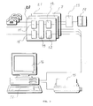
- Fig. 1 presents the on-site equipment. It consists of four main parts, one of which is the base unit 5, depicted in detail in Fig. 2. It has a few indicator devices showing the status of the equipment. An optional accessory is a keypad/display, which can be used to indicate device status in detail or for configuration.
- a car interface for the first car is included in the base unit 5. Normally, the base unit 5 is placed in the machine room of the elevator.
- a car interface unit 3 is needed when several car units 2 are connected to the base unit 5.
- the connections between the base unit 5 and the car interface units 3 are implemented using a four-wire cable.
- the car unit 2 is placed in the elevator car. It contains the electronics required for the audio and data communication and receives its power via a 2- wire connection 42.
- An I/O unit 1 is normally placed in the elevator machine room.
- the I/O unit 1 has digital inputs and outputs to be used in a level II system. Indicators show the status of each input and output.
- a car interface unit 3 for connecting a car unit 2 is integrated in the I/O unit.
- the equipment can be provided with a keypad/display, which is used to show status details or to configure the device.
- the I/O unit 1 is also provided with indicators for simple status data:
- the alarm button may be either a potential-free contact or an alarm button in an existing alarm bell circuit. By selection, it can be a NC (normally closed) or a NO (normally open) type contact.
- the alarm bell circuit may be supplied with a voltage of 6 - 48 VAC/DC.
- efficient LED types with a max. current consumption of 2 mA must be used.
- Each LED is connected to the car unit with 2 wires.
- one or two relays can be mounted for the connection of lamps requiring more current, supplied from an external power source.
- the loudspeaker and microphone to be used for voice communication are delivered with the car unit 2.
- Fig. 2 illustrates the operation of the base unit 5.
- Each base unit 5 can handle 8 elevators in one building or group of buildings.
- the on-site equipment allows the use of a 4-wire cable of a length of 1000 m between the base unit and the car interface units 3 (or I/O units 1).
- the 2-wire cable between the car unit 2 and the elevator machine room unit (base unit 5, car interface unit 3 or I/O unit 1) may be up to 300 m long.
- the on-site equipment and the receiver 20 have a no-break power supply allowing at least 8 hours of stand-by operation.
- the car unit 2 contains a user interface, comprising a push button, two lamps (LEDs), one microphone and one loudspeaker.
- the push button is used to start an emergency call, one of the lamps indicates the status of the emergency call and the other the 'car listened to' status.
- the microphone and the loudspeaker are used for voice communication after a connection to the service centre has been established.
- the 'car listened to' light is lit when the microphone is on.
- the base unit 5 has indicators for simple status data:
- the base unit 5 may also be connected to an intelligent keypad/display for the input of additional status information and for configuration of the on-site equipment.
- an intelligent keypad/display for the input of additional status information and for configuration of the on-site equipment.
- the same protocol is used as on the telephone line.
- Fig. 3 presents the service centre equipment.
- the receiver 20 is regarded as a normal office machine and is placed on a table or in a cabinet.
- the receiver 20 is a closed unit with two cables, one of which connects it to the telephone network, the other to the electrical network.
- the cabinet can accommodate a battery.
- the receiver 20 is provided with interfaces for the connection of a log printer 14, a computer 16 and an operator's telephone.
- the computer 16 has a testing program used for the installation. After the installation has been com- peleted, the normal operating program can be started. The servicing and maintenance of the on-site equipment is taken care of by the normal elevator service personnel. The on-site equipment must be so designed that it requires no servicing except for the following checks:
- the receiver 20 has its own internal no-break power supply allowing 8 hours of operation without mains supply.
- the receiver 20 is provided with a switch and a lamp indicating whether the service centre receiver 20 is unmanned.
- the receiver 20 has automatic testing functions and corresponding visual indicators for the following purposes:
- Each elevator has its own identification code which is communicated in connection with each call.
- An on-site equipment can send a message to several service centres: to the main service centre, at least two back-up service centres, to a programming service centre and also to an ordinary telephone.
- the primary function of the REM system is to report an emergency situation. An emergency situation is created by trapped passengers by pressing the alarm button in the elevator car. The system establishes a voice connection between the trapped passengers and the service centre operator.
- Another function of the system is to report elevator malfunctions and service needs. If an immediate service visit is not required, the need is reported in connection with a routine call. This function is included in level II equipment.
- the system performs an automatic self-test and reports all disturbances found in its operation.
- the self-test report comprises a battery check and the absence of mains power.
- Each on-site equipment in the system sends regular routine calls to the service centre. With the aid of this routine call, the service centre monitors the on-site equipment. If the service centre does not receive a routine call regularly, it can initiate a service visit to the site. This regular connection is also used for the reporting of low-priority service needs and for the transfer of certain parameters from the service centre to the on-site equipment.
- the service centre may call an on-site equipment to establish a connection for data communication for the setting of parameters or for the collection of data from the installation in question. A voice connection can be created as well.
- a copy call is a copy of a message previously communicated to another service centre.
- the on-site equipment is used by trapped passengers and elevator service engineers who use the on-site equipment when servicing the elevators.
- the service centre equipment is used by service centre operators.
- the base unit 5 For each type of call, the base unit 5 establishes a telephone connection to the service centre according to a phone number list.
- the first part of the data transmission from the on-site equipment consists of the identification code of the equipment and the call type.
- the call type defines the data to be transmitted. It should be possible to send several messages without interrupting the telephone connection. The service centre will then answer depending on the call type.
- Pressing the alarm button in the elevator car is the normal way to initiate an emergency call. To avoid false alarms, the alarm button has to be pressed for a certain time before an emergency call is initiated. This time period is called the 'filter time'. If the alarm button is pressed and released again for a short period, the on-time is accumulated. If the button has been released for a period longer than the 'filter time', the accumulated value is reset.
- the time filtering is the only possible filtering in a level I system. In level II systems there are options to be configured:
- a special 'voice test call' is initiated if the status 'service engineer on site' exists.
- a call can be initiated by an elevator failure or by an internal fault condition, or by internal counters or timers.
- technical alarm calls are intitiated by internal failures, including 'battery voltage low', 'mains missing during a (programmable) period' and 'no response from configured car units'.
- technical alarm calls can also be initiated by using monitoring functions based on signals from the elevator controller connected to an I/O unit. Such functions can be configured individually for each elevator.
- the conditions are to be programmed by using a combination of softtypes (predefined behavior of a certain input type) and logical functions.
- the configuration possibilities include timer functions and latches.
- Each input can be programmed with one of the sofftypes in order to achieve the desired reaction.
- For each input a text string can also be allocated, for easy identification.
- One special function could be 'automatic car calls'.
- One or two outputs are configured and connected to the elevator controller. When 'automatic car call' has been activated, the car call outputs will be activated in sequence to see if it is possible to bring the car to another position. This function could also be remotely controlled from the service centre.
- the timers can be programmed for periods ranging from a second to an hour. If a technical failure occurs, it should be possible to delay the initiation of a technical alarm call. If the car has been taken in use after the reporting of a technical failure, a cancellation report should be sent immediately.
- service calls are initiated by elevator event counters registering 1) the number of starts, 2) the number of door closings, 3) the total running time. If car position data is available, a counter for each landing door could be configured as well.
- the equipment can be configured to generate a copy call to the main service centre for each message sent to a backup service centre.
- the phone number list holds at least six phone numbers to be used for the different types of calls.
- Each phone number consists of max. 24 digits, including the coding for dialling, e.g. 'wait for dial tone', 'change to touch-tone dialling' or 'change to pulse dialling'. Automatic adjustment of time is included in the routine calls, synchronizing the automatic time/date setting function.
- the above-mentioned calling sequence and functions may be overruled by local regulations.
- the system has a built-in number checking feature to filter out certain phone numbers, like 000 or 999.
- the routine call includes an automatic time/date setting function to synchronize the on-site real-time clock with the service centre computer time/date.
- This automatic time adjustment also includes a feature allowing time zone differences between the service centre and the on-site equipment. Included in the on-site equipment are parameters to be configured for automatic adjusting of summer/winter time change independently of the routine call time.
- the base unit 5 has visual indicators for faults and status. The condition of the battery is tested every 15 seconds. If a test fails, a service call will be initiated. A complete capacity test of the battery is not included. An automatic routine call is performed at a programmed time and interval. This function can be enabled/disabled. Information about service needs is automatically transmitted when the routine call takes place. The routine call procedure must be as short as possible to minimize the load on the service centre receivers and the cost of the communication.
- All programmable functions have default values in order to minimize the configuring of the individual on-site equipment. All time-dependent events, together with the time and date, are registered in an event log. The logged information can be retrieved locally or from a service centre.
- the event log holds the information about events in a FIFO (First-In-First-Out) buffer. Memory for at least 50 events should be reserved. All types of calls made to a service centre are logged in the event log. Also events related to the base unit 5 are logged, i.e. telephone line failures, 2-wire bus failures and base unit self-test failures. Each event in the event log has a status field holding information about whether it has been successfully reported, is not reported or is not to be reported. The same event repeated at short intervals should not be allowed to fill the event log, but either be 'counted up' or not registered until the previous event has been reset. The status log maintains all status signals, e.g. 'emergency call', 'service engineer on site', 'elevator out of use', or 'service need'.
- FIFO First-In-First-Out
- This status log also includes event counter values relating to the previous service visit.
- Each elevator has its own programmable ID and address information.
- the ID code contains up to 20 characters, the address up to 40 characters.
- the address part of the message can optionally be omitted.
- the message also includes the reason for the call and the number of trials needed to come through to the receiving receiver 20.
- the car position is reported on the basis of digital inputs if available (only for level II systems).
- All parameters for the on-site equipment can be programmed/configured at the factory and down-loaded from the service centre computer via the receiver, or they can be programmed locally.
- a password When programming, whether locally or remotely, a password must be used for access to the configuration tables. The password can be changed by authorized personnel.
- the call-back trigger function is initiated upon detection of ringing.
- the no-break power supply should allow at least 8 hours of operation.
- the on-site equipment is expandable for handling up to 8 cars.
- An emergency call in progress is indicated by the ALARM lamp in the calling car and by a sound, e.g. resembling dialling tones, issued via the loudspeaker.
- a speak- mode indicator light is lit, showing that 'the car is supervised' or 'listened to' and that the microphone is connected. In broadcast mode the lamp is off.
- Call back with voice is possible as the service centre can always make a voice call to a car, even when the alarm button has not been activated. This possibility has been included mainly for testing purposes.
- the car unit and its signal lights behave exactly like in the case of an emergency call. To make a voice call to a car, the call-back function must first be triggered. A trapped passenger can repeat an emergency call by re-activating the alarm button.
- broadcast voice mode When broadcast voice mode is selected by the service centre operator, a broadcast voice message will be sent to all cars where an emergency call is in progress.
- the data communication between the base unit 5 and the service centre is implemented using an open protocol in order to provide maximum integration possibilities.
- the commands can be issued on-site.
- Voice call to a normal telephone should also be possible. See section 'phone number list'. It must be possible to select between 1) calling the service centre first to get the phone number and 2) calling the programmed phone number first.
- commands can be given via the telephone keypad (DTMF). At least one command is necessary for termination of voice mode. Other commands may be necessary, e.g. 'gain control', 'extend voice period', and 'acknowledge voice contact'.
- Full duplex communication is to be used in the system. No switch is to be used in the service centre. This also gives the possibility to make a voice call from the on-site equipment to a normal telephone.
- the service centre equipment is normally controlled by means of a computer, using its keyboard and display.
- the normal mode gives the best possible operator interface and allows a 'customer elevator database' to be integrated in the system.
- the log printer can be configured to print all received messages in normal mode.
- the service centre equipment can also be operated in back-up mode. This mode is automatically selected when the computer is not on-line, not running, not connected or not powered. When the equipment is operated in back-up mode, all emergency calls can still be handled and all received messages are printed out on the log printer.
- the functions relating to setup/control of the receiver 20 are as follows:
- the functions available to the operator include:
- the receiver 20 is provided with a number of indicators showing the status of the equipment, including a sound signal telling the operator when to take action. Voice communication takes place via a telephone head/handset. All texts in the computer are in the local language. When several alternatives are possible, help facilities and menus are available. Error messages are issued for different types of errors and failures.
- the shaft wiring needed to connect the car unit is implemented with two wires by making use of the free conductors in the existing cables.
- Each on-site equipment can be configured at the factory, by remote control from the service centre, or by using an optional keypad/display, connected either to the base unit 5 or to the I/O units 1.
- the base unit 5 is mounted in the machine room close to the elevator control panel. The mounting is to be carried out using max. four screws, without removing any devices from the box. A separate mains supply cable must be provided and all local regulations relating to electrical installations must be observed.
- the system is so designed that no earth connection is needed. However, local regulations may require the use of a protective earth connection. All terminals must be screw terminals, clearly marked, easy to find and easy to work on.
- One or two batteries are to be installed in the base unit.
- the car unit 2 is placed on the outside of the elevator car, i.e. on the back of a removable car panel.
- the car unit is designed for flexible mounting.
- the printed-circuit board of the car unit is to be mounted with 4 screws. It is provided with separately mounted screw terminals for the connection of a loudspeaker, microphone, LEDs, alarm button, and a 2-wire bus (from the base unit).
- an installation program specially designed for this purpose must be executed.
- the optional keypad/display may be connected to the base unit 5, or the program may be executed under remote control from the service centre.
- the installation program is divided into two parts:
Landscapes
- Indicating And Signalling Devices For Elevators (AREA)
- Selective Calling Equipment (AREA)
- Maintenance And Inspection Apparatuses For Elevators (AREA)
- Elevator Control (AREA)
- Surface Acoustic Wave Elements And Circuit Networks Thereof (AREA)
- Vehicle Body Suspensions (AREA)
Applications Claiming Priority (2)
| Application Number | Priority Date | Filing Date | Title |
|---|---|---|---|
| FI925842 | 1992-12-22 | ||
| FI925842A FI111934B (fi) | 1992-12-22 | 1992-12-22 | Hissilaitteiden kauko-ohjausjärjestelmä |
Publications (2)
| Publication Number | Publication Date |
|---|---|
| EP0603682A1 true EP0603682A1 (fr) | 1994-06-29 |
| EP0603682B1 EP0603682B1 (fr) | 1997-05-28 |
Family
ID=8536450
Family Applications (1)
| Application Number | Title | Priority Date | Filing Date |
|---|---|---|---|
| EP93119984A Expired - Lifetime EP0603682B1 (fr) | 1992-12-22 | 1993-12-10 | Système de télécommande pour ascenseurs |
Country Status (11)
| Country | Link |
|---|---|
| US (1) | US5445245A (fr) |
| EP (1) | EP0603682B1 (fr) |
| JP (1) | JPH06227767A (fr) |
| AT (1) | ATE153631T1 (fr) |
| AU (1) | AU678914B2 (fr) |
| BR (1) | BR9305211A (fr) |
| CA (1) | CA2112202C (fr) |
| DE (1) | DE69311082T2 (fr) |
| ES (1) | ES2101933T3 (fr) |
| FI (1) | FI111934B (fr) |
| SG (1) | SG49639A1 (fr) |
Cited By (8)
| Publication number | Priority date | Publication date | Assignee | Title |
|---|---|---|---|---|
| EP0653371A3 (fr) * | 1993-11-12 | 1996-03-27 | Otis Elevator Co | Système de surveillance à distance pour ascenseur. |
| FR2755277A1 (fr) * | 1996-10-25 | 1998-04-30 | Richardier Martin Rene | Procede de commande a distance et d'assistance pour centrale de commande et de paiement |
| DE29817351U1 (de) * | 1998-09-28 | 1999-10-07 | C. Haushahn GmbH & Co., 70469 Stuttgart | Vorrichtung zum Sonderbetrieb von Aufzugsanlagen |
| ES2137132A1 (es) * | 1996-06-06 | 1999-12-01 | Zergonsa Sur Este S L | Sistema de comunicacion de averias para ascensores. |
| ES2145689A1 (es) * | 1998-01-26 | 2000-07-01 | Apamac S A | Sistema de seguridad para ascensores. |
| SG97809A1 (en) * | 1998-09-17 | 2003-08-20 | Inventio Ag | Remote control of lift installations |
| ITRN20130022A1 (it) * | 2013-06-07 | 2014-12-08 | Liftware S R L | Sistema di telecontrollo per ascensori di tipologia diversificata |
| EP2421783B1 (fr) | 2009-04-24 | 2015-08-12 | Inventio AG | Procédé destiné à la communication à l'aide d'une installation d'ascenseur |
Families Citing this family (26)
| Publication number | Priority date | Publication date | Assignee | Title |
|---|---|---|---|---|
| US5714726A (en) * | 1992-12-22 | 1998-02-03 | Kone Oy | Method for performing an alarm call in an elevator system |
| US5736694A (en) * | 1992-12-22 | 1998-04-07 | Kone Oy | Method for providing a phone alarm call in an elevator system |
| JP3202396B2 (ja) * | 1993-03-26 | 2001-08-27 | 株式会社日立ビルシステム | エレベータの異常解析データ収集装置 |
| US5975248A (en) * | 1995-08-11 | 1999-11-02 | Drucegrove Limited | Communications system |
| US5760350A (en) * | 1996-10-25 | 1998-06-02 | Otis Elevator Company | Monitoring of elevator door performance |
| US5780787A (en) * | 1996-10-31 | 1998-07-14 | Otis Elevator Company | Monitoring of manual elevator door systems |
| US5817993A (en) * | 1996-11-27 | 1998-10-06 | Otis Elevator Company | Monitoring of elevator door reversal data |
| DE19823813B4 (de) * | 1998-03-20 | 2009-05-07 | Rud. Prey GmbH Aufzüge und Feuerwehrtechnik | Verfahren und Störfallleitsystem zur automatischen Benachrichtigung über einen eingetretenen Störfall |
| ES2154238B1 (es) * | 1999-08-06 | 2001-10-01 | J P Bastiaans Belot | Sistema de comunicacion para ascensores con emision de informacion diferida. |
| CN100337895C (zh) * | 2001-09-28 | 2007-09-19 | 东芝电梯株式会社 | 电梯的远程监视装置 |
| EP1637494A4 (fr) * | 2003-06-20 | 2009-09-16 | Mitsubishi Electric Corp | Systeme de surveillance d'ascenseurs et support d'enregistrement lisible par ordinateur dans lequel est stocke un programme de surveillance d'ascenseurs |
| US6971480B2 (en) * | 2003-08-29 | 2005-12-06 | Electronic Micro Systems Inc. | Elevator communication devices, systems and methods |
| DE102005004667B4 (de) * | 2005-02-02 | 2025-01-02 | TÜV Nord GmbH | Diagnoseeinrichtung |
| US7699142B1 (en) | 2006-05-12 | 2010-04-20 | Wurtec Elevator Products & Services | Diagnostic system having user defined sequence logic map for a transportation device |
| JP2008092599A (ja) * | 2007-11-28 | 2008-04-17 | Nokia Corp | ネットワーク識別される非常セッションを取り扱う方法及びシステム |
| KR101286181B1 (ko) * | 2009-09-16 | 2013-07-15 | 오티스 엘리베이터 컴파니 | 다중 서브시스템들을 갖는 엘리베이터 제어 시스템의 원격 접근 |
| WO2012154170A1 (fr) | 2011-05-10 | 2012-11-15 | Otis Elevator Company | Gestion de commande à distance d'un système d'ascenseur |
| CN102795519A (zh) * | 2011-05-27 | 2012-11-28 | 上海三菱电梯有限公司 | 电梯远程监控装置 |
| AU2013322887B2 (en) * | 2012-09-25 | 2017-02-23 | Inventio Ag | Method for restoring a safety system for an elevator installation |
| CN106395568B (zh) * | 2015-07-31 | 2020-05-05 | 奥的斯电梯公司 | 电梯恢复轿厢 |
| CN107176508A (zh) | 2016-03-11 | 2017-09-19 | 奥的斯电梯公司 | 电梯交互终端和电梯交互系统 |
| US10850941B2 (en) | 2016-10-29 | 2020-12-01 | Otis Elevator Company | Communication with a passenger in a transportation system |
| EP3415454B1 (fr) * | 2017-06-14 | 2021-09-22 | KONE Corporation | Compensation de défaillance automatique d'ascenseurs, d'escaliers roulants et de portes automatiques |
| US11148906B2 (en) | 2017-07-07 | 2021-10-19 | Otis Elevator Company | Elevator vandalism monitoring system |
| EP3911133B1 (fr) * | 2018-12-20 | 2025-04-02 | Zhejiang Jiecang Linear Motion Technology Co., Ltd | Dispositif de commande pour plate-forme de levage et plate-forme de levage |
| US20220177266A1 (en) * | 2020-12-04 | 2022-06-09 | Otis Elevator Company | Voice activated elevator passenger interface configuration device |
Citations (11)
| Publication number | Priority date | Publication date | Assignee | Title |
|---|---|---|---|---|
| US3973648A (en) * | 1974-09-30 | 1976-08-10 | Westinghouse Electric Corporation | Monitoring system for elevator installation |
| US4697243A (en) * | 1985-07-25 | 1987-09-29 | Westinghouse Electric Corp. | Methods of servicing an elevator system |
| JPH0256391A (ja) * | 1988-08-19 | 1990-02-26 | Mitsubishi Electric Corp | エレベータの制御装置 |
| GB2226428A (en) * | 1988-11-19 | 1990-06-27 | Hitachi Ltd | "Remote monitor and diagnosis apparatus" |
| JPH02239072A (ja) * | 1989-03-14 | 1990-09-21 | Hitachi Elevator Eng & Service Co Ltd | 昇降機制御装置 |
| JPH02268399A (ja) * | 1989-04-11 | 1990-11-02 | Hitachi Elevator Eng & Service Co Ltd | エレベータの監視装置 |
| JPH0356379A (ja) * | 1989-07-25 | 1991-03-11 | Hitachi Elevator Eng & Service Co Ltd | エレベータの遠隔監視装置 |
| JPH03200682A (ja) * | 1989-08-28 | 1991-09-02 | Hitachi Elevator Eng & Service Co Ltd | エレベータの非常通話装置 |
| US5064026A (en) * | 1989-06-13 | 1991-11-12 | Mitsubishi Denki Kabushiki Kaisha | Elevator monitor apparatus |
| JPH04235881A (ja) * | 1991-01-16 | 1992-08-24 | Toshiba Corp | 個人住宅用エレベータ非常時遠隔救出装置 |
| JPH04252650A (ja) * | 1991-01-29 | 1992-09-08 | Matsushita Electric Ind Co Ltd | エレベータの通報装置 |
Family Cites Families (6)
| Publication number | Priority date | Publication date | Assignee | Title |
|---|---|---|---|---|
| US4431086A (en) * | 1982-01-29 | 1984-02-14 | Westinghouse Electric Corp. | Elevator system |
| DE3763766D1 (de) * | 1986-07-07 | 1990-08-23 | Inventio Ag | System zur fernverwaltung von aufzugsanlagen. |
| US4823914A (en) * | 1987-06-24 | 1989-04-25 | Elevator Performance Technologies, Inc. | Status line monitoring system and method of using same |
| JPH0737306B2 (ja) * | 1989-05-18 | 1995-04-26 | 三菱電機株式会社 | エレベータ遠隔制御方法 |
| JPH03172294A (ja) * | 1989-11-28 | 1991-07-25 | Mitsubishi Electric Corp | エレベーターの防犯装置 |
| JPH0420465A (ja) * | 1990-05-14 | 1992-01-24 | Toshiba Corp | エレベータの遠隔保守装置 |
-
1992
- 1992-12-22 FI FI925842A patent/FI111934B/fi not_active IP Right Cessation
-
1993
- 1993-12-10 EP EP93119984A patent/EP0603682B1/fr not_active Expired - Lifetime
- 1993-12-10 DE DE69311082T patent/DE69311082T2/de not_active Expired - Lifetime
- 1993-12-10 AT AT93119984T patent/ATE153631T1/de active
- 1993-12-10 ES ES93119984T patent/ES2101933T3/es not_active Expired - Lifetime
- 1993-12-10 SG SG1996002225A patent/SG49639A1/en unknown
- 1993-12-13 US US08/165,597 patent/US5445245A/en not_active Expired - Lifetime
- 1993-12-20 JP JP5344488A patent/JPH06227767A/ja active Pending
- 1993-12-22 CA CA002112202A patent/CA2112202C/fr not_active Expired - Lifetime
- 1993-12-22 BR BR9305211A patent/BR9305211A/pt not_active IP Right Cessation
-
1995
- 1995-11-06 AU AU36657/95A patent/AU678914B2/en not_active Expired
Patent Citations (11)
| Publication number | Priority date | Publication date | Assignee | Title |
|---|---|---|---|---|
| US3973648A (en) * | 1974-09-30 | 1976-08-10 | Westinghouse Electric Corporation | Monitoring system for elevator installation |
| US4697243A (en) * | 1985-07-25 | 1987-09-29 | Westinghouse Electric Corp. | Methods of servicing an elevator system |
| JPH0256391A (ja) * | 1988-08-19 | 1990-02-26 | Mitsubishi Electric Corp | エレベータの制御装置 |
| GB2226428A (en) * | 1988-11-19 | 1990-06-27 | Hitachi Ltd | "Remote monitor and diagnosis apparatus" |
| JPH02239072A (ja) * | 1989-03-14 | 1990-09-21 | Hitachi Elevator Eng & Service Co Ltd | 昇降機制御装置 |
| JPH02268399A (ja) * | 1989-04-11 | 1990-11-02 | Hitachi Elevator Eng & Service Co Ltd | エレベータの監視装置 |
| US5064026A (en) * | 1989-06-13 | 1991-11-12 | Mitsubishi Denki Kabushiki Kaisha | Elevator monitor apparatus |
| JPH0356379A (ja) * | 1989-07-25 | 1991-03-11 | Hitachi Elevator Eng & Service Co Ltd | エレベータの遠隔監視装置 |
| JPH03200682A (ja) * | 1989-08-28 | 1991-09-02 | Hitachi Elevator Eng & Service Co Ltd | エレベータの非常通話装置 |
| JPH04235881A (ja) * | 1991-01-16 | 1992-08-24 | Toshiba Corp | 個人住宅用エレベータ非常時遠隔救出装置 |
| JPH04252650A (ja) * | 1991-01-29 | 1992-09-08 | Matsushita Electric Ind Co Ltd | エレベータの通報装置 |
Non-Patent Citations (9)
| Title |
|---|
| PATENT ABSTRACTS OF JAPAN vol. 14, no. 224 (M - 0972) 11 May 1990 (1990-05-11) * |
| PATENT ABSTRACTS OF JAPAN vol. 14, no. 563 (M - 1058) 14 December 1990 (1990-12-14) * |
| PATENT ABSTRACTS OF JAPAN vol. 15, no. 208 (M - 1117) 28 May 1991 (1991-05-28) * |
| PATENT ABSTRACTS OF JAPAN vol. 15, no. 24 (P - 1156) 21 January 1991 (1991-01-21) * |
| PATENT ABSTRACTS OF JAPAN vol. 15, no. 468 (M - 1184) 27 November 1991 (1991-11-27) * |
| PATENT ABSTRACTS OF JAPAN vol. 16, no. 181 (M - 1242) 30 April 1992 (1992-04-30) * |
| PATENT ABSTRACTS OF JAPAN vol. 16, no. 195 (M - 1246) 12 May 1992 (1992-05-12) * |
| PATENT ABSTRACTS OF JAPAN vol. 17, no. 2 (M - 1348) 5 January 1993 (1993-01-05) * |
| PATENT ABSTRACTS OF JAPAN vol. 17, no. 32 (E - 1309) 21 January 1993 (1993-01-21) * |
Cited By (10)
| Publication number | Priority date | Publication date | Assignee | Title |
|---|---|---|---|---|
| EP0653371A3 (fr) * | 1993-11-12 | 1996-03-27 | Otis Elevator Co | Système de surveillance à distance pour ascenseur. |
| ES2137132A1 (es) * | 1996-06-06 | 1999-12-01 | Zergonsa Sur Este S L | Sistema de comunicacion de averias para ascensores. |
| FR2755277A1 (fr) * | 1996-10-25 | 1998-04-30 | Richardier Martin Rene | Procede de commande a distance et d'assistance pour centrale de commande et de paiement |
| WO1998019442A1 (fr) * | 1996-10-25 | 1998-05-07 | Richardier Martin Rene | Procede de commande a distance et d'assistance pour centrale de commande et de paiement |
| ES2145689A1 (es) * | 1998-01-26 | 2000-07-01 | Apamac S A | Sistema de seguridad para ascensores. |
| SG97809A1 (en) * | 1998-09-17 | 2003-08-20 | Inventio Ag | Remote control of lift installations |
| DE29817351U1 (de) * | 1998-09-28 | 1999-10-07 | C. Haushahn GmbH & Co., 70469 Stuttgart | Vorrichtung zum Sonderbetrieb von Aufzugsanlagen |
| EP2421783B1 (fr) | 2009-04-24 | 2015-08-12 | Inventio AG | Procédé destiné à la communication à l'aide d'une installation d'ascenseur |
| ITRN20130022A1 (it) * | 2013-06-07 | 2014-12-08 | Liftware S R L | Sistema di telecontrollo per ascensori di tipologia diversificata |
| EP2840052A1 (fr) * | 2013-06-07 | 2015-02-25 | Liftware S.r.l. | Système de controle à distance pour ascenseurs |
Also Published As
| Publication number | Publication date |
|---|---|
| DE69311082T2 (de) | 1997-11-06 |
| AU678914B2 (en) | 1997-06-12 |
| US5445245A (en) | 1995-08-29 |
| AU3665795A (en) | 1996-03-21 |
| AU3665695A (en) | 1996-03-21 |
| SG49639A1 (en) | 1998-06-15 |
| EP0603682B1 (fr) | 1997-05-28 |
| BR9305211A (pt) | 1994-06-28 |
| DE69311082D1 (de) | 1997-07-03 |
| FI925842A0 (fi) | 1992-12-22 |
| AU678913B2 (en) | 1997-06-12 |
| FI925842L (fi) | 1994-06-23 |
| CA2112202C (fr) | 1997-07-01 |
| AU665878B2 (en) | 1996-01-18 |
| JPH06227767A (ja) | 1994-08-16 |
| AU5254293A (en) | 1994-07-07 |
| CA2112202A1 (fr) | 1994-06-23 |
| ES2101933T3 (es) | 1997-07-16 |
| ATE153631T1 (de) | 1997-06-15 |
| FI111934B (fi) | 2003-10-15 |
Similar Documents
| Publication | Publication Date | Title |
|---|---|---|
| EP0603682B1 (fr) | Système de télécommande pour ascenseurs | |
| US5736694A (en) | Method for providing a phone alarm call in an elevator system | |
| US5714726A (en) | Method for performing an alarm call in an elevator system | |
| JPH0630776Y2 (ja) | エレベータ設備の遠隔管理装置 | |
| US5200987A (en) | Remote supervisory monitoring and control apparatus connected to monitored equipment | |
| GB2106354A (en) | Alarm monitor | |
| WO2009010481A1 (fr) | Système de bus série destiné à être utilisé dans des ascenseurs et d'autres appareils de levage ou analogues | |
| FI107726B (fi) | Menetelmä hissijärjestelmän toiminnan testaamiseksi | |
| US4651339A (en) | Multi-subscriber warning system | |
| EP0084685B1 (fr) | Centre de commande d'alarme | |
| JPH1069591A (ja) | 集合住宅警報監視統合システム | |
| KR100714079B1 (ko) | 방재,방송통합중계장치 | |
| JPH1074294A (ja) | 集合住宅警報監視統合システム | |
| JP2507684B2 (ja) | エレベ―タ―遠隔監視装置 | |
| JPH0317501Y2 (fr) | ||
| GB2226934A (en) | Radio communication system | |
| CN222286299U (zh) | 一种多期建设的火灾报警处置系统 | |
| JPS62181594A (ja) | 集合住宅用集中監視システム | |
| JPH06164750A (ja) | エレベータかご内通話装置 | |
| JPH06243368A (ja) | 防災監視装置 | |
| KR100509829B1 (ko) | 휠체어리프트원격관제시스템 | |
| JPH03182197A (ja) | 中央監視システムによる管理ビル群夜間在宅管理システム | |
| JPH02198992A (ja) | エレベーター遠隔監視機構の点検装置 | |
| JPH1145388A (ja) | 集合住宅システム | |
| JP3028864B2 (ja) | エレベータの通報装置 |
Legal Events
| Date | Code | Title | Description |
|---|---|---|---|
| PUAI | Public reference made under article 153(3) epc to a published international application that has entered the european phase |
Free format text: ORIGINAL CODE: 0009012 |
|
| AK | Designated contracting states |
Kind code of ref document: A1 Designated state(s): AT BE CH DE DK ES FR GB GR IE IT LI LU MC NL PT SE |
|
| 17P | Request for examination filed |
Effective date: 19940727 |
|
| 17Q | First examination report despatched |
Effective date: 19960401 |
|
| GRAG | Despatch of communication of intention to grant |
Free format text: ORIGINAL CODE: EPIDOS AGRA |
|
| GRAH | Despatch of communication of intention to grant a patent |
Free format text: ORIGINAL CODE: EPIDOS IGRA |
|
| GRAH | Despatch of communication of intention to grant a patent |
Free format text: ORIGINAL CODE: EPIDOS IGRA |
|
| GRAA | (expected) grant |
Free format text: ORIGINAL CODE: 0009210 |
|
| AK | Designated contracting states |
Kind code of ref document: B1 Designated state(s): AT BE CH DE DK ES FR GB GR IE IT LI LU MC NL PT SE |
|
| PG25 | Lapsed in a contracting state [announced via postgrant information from national office to epo] |
Ref country code: GR Free format text: LAPSE BECAUSE OF FAILURE TO SUBMIT A TRANSLATION OF THE DESCRIPTION OR TO PAY THE FEE WITHIN THE PRESCRIBED TIME-LIMIT Effective date: 19970528 Ref country code: DK Effective date: 19970528 |
|
| REF | Corresponds to: |
Ref document number: 153631 Country of ref document: AT Date of ref document: 19970615 Kind code of ref document: T |
|
| REG | Reference to a national code |
Ref country code: CH Ref legal event code: EP |
|
| REF | Corresponds to: |
Ref document number: 69311082 Country of ref document: DE Date of ref document: 19970703 |
|
| REG | Reference to a national code |
Ref country code: ES Ref legal event code: FG2A Ref document number: 2101933 Country of ref document: ES Kind code of ref document: T3 |
|
| ET | Fr: translation filed | ||
| PG25 | Lapsed in a contracting state [announced via postgrant information from national office to epo] |
Ref country code: PT Effective date: 19970828 |
|
| REG | Reference to a national code |
Ref country code: CH Ref legal event code: NV Representative=s name: KELLER & PARTNER PATENTANWAELTE AG |
|
| PG25 | Lapsed in a contracting state [announced via postgrant information from national office to epo] |
Ref country code: LU Free format text: LAPSE BECAUSE OF NON-PAYMENT OF DUE FEES Effective date: 19971210 Ref country code: IE Free format text: LAPSE BECAUSE OF NON-PAYMENT OF DUE FEES Effective date: 19971210 |
|
| PLBE | No opposition filed within time limit |
Free format text: ORIGINAL CODE: 0009261 |
|
| STAA | Information on the status of an ep patent application or granted ep patent |
Free format text: STATUS: NO OPPOSITION FILED WITHIN TIME LIMIT |
|
| 26N | No opposition filed | ||
| PG25 | Lapsed in a contracting state [announced via postgrant information from national office to epo] |
Ref country code: MC Free format text: LAPSE BECAUSE OF NON-PAYMENT OF DUE FEES Effective date: 19980630 |
|
| REG | Reference to a national code |
Ref country code: CH Ref legal event code: PFA Free format text: KONE OY TRANSFER- KONE CORPORATION |
|
| REG | Reference to a national code |
Ref country code: GB Ref legal event code: IF02 |
|
| PGFP | Annual fee paid to national office [announced via postgrant information from national office to epo] |
Ref country code: CH Payment date: 20121221 Year of fee payment: 20 |
|
| PGFP | Annual fee paid to national office [announced via postgrant information from national office to epo] |
Ref country code: SE Payment date: 20121220 Year of fee payment: 20 Ref country code: IT Payment date: 20121221 Year of fee payment: 20 Ref country code: GB Payment date: 20121220 Year of fee payment: 20 Ref country code: ES Payment date: 20121217 Year of fee payment: 20 |
|
| PGFP | Annual fee paid to national office [announced via postgrant information from national office to epo] |
Ref country code: AT Payment date: 20121212 Year of fee payment: 20 |
|
| PGFP | Annual fee paid to national office [announced via postgrant information from national office to epo] |
Ref country code: DE Payment date: 20121220 Year of fee payment: 20 Ref country code: BE Payment date: 20121219 Year of fee payment: 20 Ref country code: FR Payment date: 20130130 Year of fee payment: 20 |
|
| PGFP | Annual fee paid to national office [announced via postgrant information from national office to epo] |
Ref country code: NL Payment date: 20121220 Year of fee payment: 20 |
|
| REG | Reference to a national code |
Ref country code: DE Ref legal event code: R071 Ref document number: 69311082 Country of ref document: DE |
|
| REG | Reference to a national code |
Ref country code: NL Ref legal event code: V4 Effective date: 20131210 |
|
| BE20 | Be: patent expired |
Owner name: *KONE OY Effective date: 20131210 |
|
| REG | Reference to a national code |
Ref country code: CH Ref legal event code: PL |
|
| REG | Reference to a national code |
Ref country code: GB Ref legal event code: PE20 Expiry date: 20131209 |
|
| REG | Reference to a national code |
Ref country code: AT Ref legal event code: MK07 Ref document number: 153631 Country of ref document: AT Kind code of ref document: T Effective date: 20131210 |
|
| PG25 | Lapsed in a contracting state [announced via postgrant information from national office to epo] |
Ref country code: DE Free format text: LAPSE BECAUSE OF EXPIRATION OF PROTECTION Effective date: 20131211 Ref country code: GB Free format text: LAPSE BECAUSE OF EXPIRATION OF PROTECTION Effective date: 20131209 |
|
| REG | Reference to a national code |
Ref country code: SE Ref legal event code: EUG |
|
| REG | Reference to a national code |
Ref country code: ES Ref legal event code: FD2A Effective date: 20140306 |
|
| PG25 | Lapsed in a contracting state [announced via postgrant information from national office to epo] |
Ref country code: ES Free format text: LAPSE BECAUSE OF EXPIRATION OF PROTECTION Effective date: 20131211 |