EP0603703A1 - Appareil de lecture - Google Patents
Appareil de lecture Download PDFInfo
- Publication number
- EP0603703A1 EP0603703A1 EP93120073A EP93120073A EP0603703A1 EP 0603703 A1 EP0603703 A1 EP 0603703A1 EP 93120073 A EP93120073 A EP 93120073A EP 93120073 A EP93120073 A EP 93120073A EP 0603703 A1 EP0603703 A1 EP 0603703A1
- Authority
- EP
- European Patent Office
- Prior art keywords
- reading
- lens
- reading device
- light bar
- incandescent lamp
- Prior art date
- Legal status (The legal status is an assumption and is not a legal conclusion. Google has not performed a legal analysis and makes no representation as to the accuracy of the status listed.)
- Granted
Links
Images


Classifications
-
- G—PHYSICS
- G02—OPTICS
- G02B—OPTICAL ELEMENTS, SYSTEMS OR APPARATUS
- G02B25/00—Eyepieces; Magnifying glasses
- G02B25/02—Eyepieces; Magnifying glasses with means for illuminating object viewed
Definitions
- the invention relates to a reader with the features mentioned in the preamble of claim 1.
- a reader of the type mentioned is known for example from DE utility model 8807303.3. It contains a reading lens carried by a stand that can be placed on the reading material and a rod-shaped plano-convex lens held by the stand and lying directly on the reading material for highlighting or marking a line of the reading material.
- the plane-convex lens is arranged parallel to the line direction and, on its plan side facing the reading material, additionally has an orientation line likewise arranged parallel to the line direction.
- the known reading devices have the disadvantage that the reading material is enlarged more in the area of the rod-shaped lens than in the remaining field of view of the reading lens. In particular, the optical distortions occurring at the edge of the rod-shaped lens have a disruptive effect.
- the marking is then a light bar generated on the reading material.
- the enlarged section of the reading material generated by the reading lens of the reading device has a uniform magnification.
- the measure according to claim 5 makes it possible to pivot the reading lens from its basic position, in which its plane level runs parallel to the reading material, into an inclined position pointing towards the user. The user therefore does not have to bend over the reader, but can use it from a normal sitting position.
- the measures according to claim 7 and 8 ensure that practically no dazzling light rays can get directly into the eye of the beholder from the incandescent lamp.
- Claim 10 specifies an advantageous possibility for generating a light bar on the reading material.
- the light rays emitted by the incandescent lamp are focused by a converging lens and reflected on the reading material by a deflecting mirror.
- the bias-spherical converging lens according to claim 11 has the advantage that it has a larger aperture ratio compared to a spherical converging lens. Their light output is increased accordingly.
- the arrangement of the incandescent lamp mentioned in claim 12 ensures that the light emanating from it is transformed by the converging lens into an almost parallel light beam. In addition, it is achieved that the filament or filament of the incandescent lamp itself is not shown on the reading material.
- the distance between the lens and the incandescent lamp can be varied in order to position the incandescent filament in the focal point of the lens.
- a convenient way to generate a light bar is given.
- the parallel beam of rays emanating from the converging lens strikes a strip-shaped deflecting mirror.
- a surface segment corresponding to the mirror surface is quasi cut out of the incident beam and reflected on the reading material.
- Further advantageous configurations of the mirror surface are specified in the description. For example, it can be convexly bulged in the direction of the incandescent lamp, in order to thereby extend what is produced on the reading material Effect light bar.
- the width of the mirror surface can be continuously reduced in order to compensate for the widening or widening of the light bar as the distance from the deflecting mirror increases.
- Another possibility for generating a light bar is specified in claim 15.
- an aperture with a slit-shaped passage opening is arranged in front of or behind the converging lens.
- the emerging bundle of rays which is approximately rectangular in cross section, is reflected by the deflecting mirror onto the reading material, with the illustration of a light bar.
- the deflecting mirror does not have to be adapted to the shape or the width of the light bar. In this case too, it is possible to counteract the expansion of the light bar, for example by a corresponding curvature of the mirror surface.
- the light generated by the incandescent lamp is deflected directly onto the reading material by an optical element, for example a lens or a prism.
- a deflection mirror is therefore not necessary in this embodiment.
- the deflection can expediently be achieved by tilting the converging lens.
- the optical axis of the lens then forms an acute angle open to the incandescent lamp with the plane of the reading material.
- the light generated by the incandescent lamp is thus converted into a parallel bundle of rays directed at the reading material.
- a lens with two side surfaces running parallel to one another and to the optical axis of the lens is used to generate the light bar.
- the lens or lens segment has a rectangular outline in the direction of view of its optical axis.
- the light bar can also be produced by a diaphragm arranged in front of the lens or the prism with a passage opening corresponding to the shape of the light bar.
- the measure according to claim 20 supports the illumination of the visual field.
- the coloring of the lenses specified in claim 21 or the interposition or interposition of color filters enables individual adaptation to color ametropia.
- an embodiment is specified in which the light bar is generated only by a slit-shaped diaphragm.
- a collecting lens can be omitted when using a correspondingly powerful light bulb.
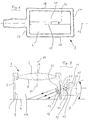
- the reading device designated as a whole by 1 contains a frame 2 designed in the manner of an envelope.
- the lower end of the frame 2 forms an attachment edge 3 for placing the reading device on a reading material 4, for example a book page.
- the upper end of the frame 2, seen in cross-section, is bent inward in the shape of a hook and, with its edge 5 pointing towards the reading material 4, carries a reading lens 6.
- the reading lens 6 is a biconvex aspherical converging lens, the top side 7 of which faces the eye of the viewer is more curved than the underside 8 facing the reading material 8.
- the optical axis 10 of the reading lens 6 runs approximately at right angles to the flat surface of the reading material 4 in use.
- the frame does not necessarily have to be closed all around. It can also have lateral openings or be approximately U-shaped, the free ends of the U-legs being supported on the reading material.
- a handle 12 is fastened or formed on the side of the frame 2, the central longitudinal axis 13 of which intersects the optical axis 10 of the reading lens 6 at right angles and runs radially to the latter.
- the handle 12 is positioned in the direction of the optical axis 10 between the reading lens 6 and reading material 4. It is approximately circular in cross section and has such a cavity 14.
- the cavity contains a lighting system for generating a light bar 15 (FIG. 6) on the reading material 4 and for illuminating the entire field of view.
- a battery (not shown) is arranged in the part of the cavity 14 facing away from the optical axis 10.
- a power supply with a power supply unit is of course also possible.
- the cavity opens via an opening 16 into the interior 17 of the reading device enclosed by the frame 2.
- a component 18 which contains a converging lens 19, a lamp holder 20 and an incandescent lamp 21 fastened therein.
- the component 18 is essentially a tube section, the end of which faces away from the interior 17 carries the lamp holder and on the other end of which a tube 22 carrying the converging lens 19 is slidably and removably attached.
- the entire component 18 lies positively and removably in the cavity 14 of the handle 12.
- the incandescent lamp 21 can be switched on with a switch (not shown) arranged on the handle 12. It is positioned so that its filament 33 is at the focal point of the converging lens 19. Their light is therefore shaped by the converging lens 19 into an almost parallel beam.
- the illuminance of the incandescent lamp can be adjusted with a trim potentiometer (not shown) on the handle.
- a deflection mirror 23 is arranged on the inside of the frame 2 diametrically opposite the converging lens 19, which deflects the light bundle emanating from the converging lens 19 onto the reading material 4, depicting the light bar 15 (FIG. 6).
- the mirror surface 24 is inclined towards the reading material. With the optical axis 10 of the reading lens 6, it forms an acute angle ⁇ which is open towards the reading material 4.
- the width 25 (FIG. 2) of the mirror surface 24 corresponds approximately to the width 26 (FIG. 6) of the light bar 15.
- the converging lens 19 is a bias-spherical lens.
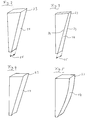
- the deflecting mirror according to Figure 2 has a flat mirror surface 24 with a rectangular outline.
- the width 25 of the mirror surface 24 corresponds to the width 26 of the light bar 15.
- the deflecting mirror shown in FIG. 4 has a mirror surface 24 which is concavely curved in the width direction. Light rays striking the deflecting mirror are focused and thus the luminosity of the light bar 15 is increased. 5 finally shows a deflecting mirror, the mirror surface 24 of which is convexly curved in the longitudinal direction.
- This configuration makes it possible to extend the light bar 15 in the case of relatively wide reading devices covering a larger area of the line width of the reading material.
- deflecting mirrors other configurations are of course also conceivable, for example a combination of the mirror surface shapes according to FIGS. 3 and 4.
- FIG. 6 shows an embodiment of a reading device 1, the frame of which is rectangular in cross section.
- the handle 12 is formed on a narrow side 27 of the frame 2 such that its central longitudinal axis 13 runs radially to the optical axis 10 of the reading lens 6 and parallel to the long sides 28 of the frame 2.
- the light bar 15 runs parallel to the central longitudinal axis 13 of the handle and to the longitudinal sides 28 of the frame and intersects the optical axis 10 of the reading lens 6.
- the converging lens 29 is arranged here in such a way that its optical axis 30 forms an acute angle ⁇ open to the incandescent lamp 21 with the flat surface of the reading material 4.
- the converging lens 29 is a bias lens.
- a diaphragm 31 is arranged between the incandescent lamp 21 and the converging lens 29 within the cavity 14.
- the aperture (not shown) has an outline shape that is suitable for producing a light bar 15.
- the diaphragm 31 may also be arranged, in deviation from FIG. 7, so that its flat surface is perpendicular to the optical axis 30 of the lens 29.
- a color filter is arranged between the converging lens 29 and the diaphragm 31. However, it can also be positioned between the diaphragm 31 and the bulb 21. To produce a color effect, however, it is also conceivable to use a colored lens or a colored light bulb. The options described here for generating a colored light can also be applied to the embodiment described above.
- FIG. 8 shows an exemplary embodiment in which the shape of the light bar 15 generated on the reading material 4 is not generated by an aperture, but by the shape of the converging lens (segment 34).
- the lens has two side surfaces 35 running parallel to one another and parallel to its optical axis 30.
- the lens thus corresponds approximately to a strip-shaped segment 34 which was cut out from the apex region of a converging lens.
- the distance 36 between the two side surfaces 35 corresponds approximately to the width 26 of the light bar 15.
- the segment 34 is also arranged in such a way that its optical axis 30 with the flat surface of the reading material 4 is pointed towards the incandescent lamp 21 Forms angle ⁇ .
- the light emerging from the cavity 14 laterally past the side surfaces 35 of the segment 34 serves to illuminate the entire field of view.
- a matt screen 37 is fitted in the opening edge of the opening 16 of the cavity 14.
- the flat surface of the focusing screen runs at right angles to the optical axis 30 of the segment 34.
- the segment 34 finally lies in a central opening 38 of the focusing screen 37 shaped in the manner of a rectangular slot and is fixed there.
- the side surfaces 35 run at right angles to the plane of the focusing screen 37.
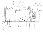
- the light bar is generated on the reading material in that a diaphragm 39 is arranged in front of the incandescent lamp 21.
- the aperture (not shown) is designed in the manner of a rectangular slot. The width of the rectangular slit increases in the direction of the reading material in order to compensate for the expansion of the light bar already mentioned above.
- the aperture 39 as shown in FIG. 11, can be inclined towards the reading material or can be arranged at right angles thereto or parallel to the optical axis 10 of the reading lens 6.
- Reference list 35 Side surface 1 Reader 36 distance 2nd frame 37 Focusing screen 3rd Touch edge 38 opening 4th Reading material 39 cover 5 Edge 6 Reading lens ⁇ angle 7 Top ⁇ angle 8th bottom 9 inside 10th optical axis 11 Central longitudinal axis 12th Handle 13 Central longitudinal axis 14 cavity 15 Light bar 16 opening 17th inner space 18th Component 19th Converging lens 20th Lamp holder 21 Light bulb 22 Tube 23 Deflecting mirror 24th Mirror surface 25th width 26 width 27 Narrow side 28 Long sides 29 Converging lens 30th optical axis 31 cover 32 Color filter 33 Incandescent filament 34 segment
Landscapes
- Physics & Mathematics (AREA)
- General Physics & Mathematics (AREA)
- Optics & Photonics (AREA)
- Holo Graphy (AREA)
- Lenses (AREA)
- Surgical Instruments (AREA)
- Inspection Of Paper Currency And Valuable Securities (AREA)
- Lubrication Of Internal Combustion Engines (AREA)
- Facsimile Scanning Arrangements (AREA)
- Character Input (AREA)
Applications Claiming Priority (2)
| Application Number | Priority Date | Filing Date | Title |
|---|---|---|---|
| DE9217484U | 1992-12-22 | ||
| DE9217484U DE9217484U1 (de) | 1992-12-22 | 1992-12-22 | Lesegerät |
Publications (2)
| Publication Number | Publication Date |
|---|---|
| EP0603703A1 true EP0603703A1 (fr) | 1994-06-29 |
| EP0603703B1 EP0603703B1 (fr) | 1995-09-27 |
Family
ID=6887413
Family Applications (1)
| Application Number | Title | Priority Date | Filing Date |
|---|---|---|---|
| EP93120073A Expired - Lifetime EP0603703B1 (fr) | 1992-12-22 | 1993-12-13 | Appareil de lecture |
Country Status (3)
| Country | Link |
|---|---|
| EP (1) | EP0603703B1 (fr) |
| AT (1) | ATE128559T1 (fr) |
| DE (2) | DE9217484U1 (fr) |
Cited By (1)
| Publication number | Priority date | Publication date | Assignee | Title |
|---|---|---|---|---|
| WO2008086780A3 (fr) * | 2007-01-17 | 2008-09-25 | Schweizer Gmbh Optische Fabrik | Loupe à poser |
Families Citing this family (3)
| Publication number | Priority date | Publication date | Assignee | Title |
|---|---|---|---|---|
| DE10238389B4 (de) * | 2002-08-16 | 2006-03-16 | A. Schweizer Gmbh Optische Fabrik | Vergrößernde optische Einrichtung |
| DE102007023316A1 (de) * | 2007-05-16 | 2008-12-18 | Frank Abert | Gerät zum Untersuchen eines Objektes |
| DE102010010464B4 (de) | 2010-03-06 | 2011-11-17 | Bcd-Gmbh | Lesehilfe |
Citations (6)
| Publication number | Priority date | Publication date | Assignee | Title |
|---|---|---|---|---|
| US3945717A (en) * | 1974-10-10 | 1976-03-23 | Ryder International Corporation | Illuminating magnifying lens structure |
| DE2846072A1 (de) * | 1978-10-23 | 1980-04-30 | Karl Schwarz | Beleuchteter lesestab |
| EP0277024A1 (fr) * | 1987-01-28 | 1988-08-03 | Combined Optical Industries Limited | Loupe à support |
| DE8807303U1 (de) * | 1988-06-04 | 1988-10-13 | Eschenbach Optik GmbH + Co, 8500 Nürnberg | Lese- und Betrachtungsgerät |
| US4859032A (en) * | 1988-04-15 | 1989-08-22 | Designs For Vision, Inc. | Hand-held magnifier apparatus |
| DE9000190U1 (de) * | 1990-01-09 | 1990-02-22 | Heine Optotechnik GmbH & Co KG, 82211 Herrsching | Lupe |
-
1992
- 1992-12-22 DE DE9217484U patent/DE9217484U1/de not_active Expired - Lifetime
-
1993
- 1993-12-13 AT AT93120073T patent/ATE128559T1/de not_active IP Right Cessation
- 1993-12-13 DE DE59300684T patent/DE59300684D1/de not_active Expired - Lifetime
- 1993-12-13 EP EP93120073A patent/EP0603703B1/fr not_active Expired - Lifetime
Patent Citations (6)
| Publication number | Priority date | Publication date | Assignee | Title |
|---|---|---|---|---|
| US3945717A (en) * | 1974-10-10 | 1976-03-23 | Ryder International Corporation | Illuminating magnifying lens structure |
| DE2846072A1 (de) * | 1978-10-23 | 1980-04-30 | Karl Schwarz | Beleuchteter lesestab |
| EP0277024A1 (fr) * | 1987-01-28 | 1988-08-03 | Combined Optical Industries Limited | Loupe à support |
| US4859032A (en) * | 1988-04-15 | 1989-08-22 | Designs For Vision, Inc. | Hand-held magnifier apparatus |
| DE8807303U1 (de) * | 1988-06-04 | 1988-10-13 | Eschenbach Optik GmbH + Co, 8500 Nürnberg | Lese- und Betrachtungsgerät |
| DE9000190U1 (de) * | 1990-01-09 | 1990-02-22 | Heine Optotechnik GmbH & Co KG, 82211 Herrsching | Lupe |
Cited By (1)
| Publication number | Priority date | Publication date | Assignee | Title |
|---|---|---|---|---|
| WO2008086780A3 (fr) * | 2007-01-17 | 2008-09-25 | Schweizer Gmbh Optische Fabrik | Loupe à poser |
Also Published As
| Publication number | Publication date |
|---|---|
| ATE128559T1 (de) | 1995-10-15 |
| EP0603703B1 (fr) | 1995-09-27 |
| DE9217484U1 (de) | 1994-04-21 |
| DE59300684D1 (de) | 1995-11-02 |
Similar Documents
| Publication | Publication Date | Title |
|---|---|---|
| EP0417039B1 (fr) | Dispositif d'éclairage pour projecteur | |
| DE69317103T2 (de) | Beleuchtungssystem zur Inspektion von Kontaktlinsen | |
| EP0930600B1 (fr) | Elément optique ayant DEL et deux lentilles pour la génération des points de lumière pour panneaux de signalisation et d'affichage | |
| DE3442218C2 (fr) | ||
| DE2535144B2 (de) | Schlitzbeleuchtungseinrichtung für ein Kopiergerät | |
| EP0623780A2 (fr) | Lentille de projection pour phase de véhicule | |
| DE2925407A1 (de) | Auflicht-beleuchtungseinrichtung fuer mikroskope | |
| DE1952358A1 (de) | Zahnbehandlungs- bzw. Operationslampe | |
| EP0991972A2 (fr) | Dispositif de projection | |
| DE1201275B (de) | Scheinwerfer zum Ausleuchten einer recht-winkligen Flaeche | |
| EP0603703B1 (fr) | Appareil de lecture | |
| DE4227942C2 (de) | Spaltlampen-Beleuchtungseinrichtung | |
| DE1913711A1 (de) | Beleuchtungssystem fuer optische Instrumente | |
| DE19819245C1 (de) | Vorrichtung mit einem Objektiv zum Abbilden | |
| DE102004026141B4 (de) | Optisches Beobachtungsgerät und Verfahren zum Anpassen eines optischen Beobachtungsgerätes | |
| DE3708647C2 (fr) | ||
| DE10231531B4 (de) | Schutzrohrleuchte | |
| DE3519190C2 (de) | Meßlichtprojektor für ein Spektralmeßgerät | |
| DE741213C (de) | Blendfreier elektrischer Scheinwerfer, insbesondere fuer Kraftfahrzeuge | |
| DE9411145U1 (de) | Realbild-Auflichtprojektor | |
| DE9202306U1 (de) | Beleuchtungseinrichtung, insbesondere für Bildverarbeitungssysteme | |
| DE4215128C2 (de) | Spaltlampe mit veränderbarem Spaltlicht-Einstrahlwinkel | |
| AT405212B (de) | Optisches element | |
| DE29621092U1 (de) | Anordnung zur Auflicht-Objektbeleuchtung | |
| DE2545526C3 (de) | Durchlicht-Beleuchtungsapparat für ein Mikroskop |
Legal Events
| Date | Code | Title | Description |
|---|---|---|---|
| PUAI | Public reference made under article 153(3) epc to a published international application that has entered the european phase |
Free format text: ORIGINAL CODE: 0009012 |
|
| AK | Designated contracting states |
Kind code of ref document: A1 Designated state(s): AT BE CH DE DK ES FR GB GR IE IT LI LU NL PT SE |
|
| 17P | Request for examination filed |
Effective date: 19940618 |
|
| 17Q | First examination report despatched |
Effective date: 19940923 |
|
| GRAA | (expected) grant |
Free format text: ORIGINAL CODE: 0009210 |
|
| AK | Designated contracting states |
Kind code of ref document: B1 Designated state(s): AT BE CH DE DK ES FR GB GR IE IT LI LU NL PT SE |
|
| PG25 | Lapsed in a contracting state [announced via postgrant information from national office to epo] |
Ref country code: NL Free format text: LAPSE BECAUSE OF FAILURE TO SUBMIT A TRANSLATION OF THE DESCRIPTION OR TO PAY THE FEE WITHIN THE PRESCRIBED TIME-LIMIT Effective date: 19950927 Ref country code: GR Free format text: LAPSE BECAUSE OF FAILURE TO SUBMIT A TRANSLATION OF THE DESCRIPTION OR TO PAY THE FEE WITHIN THE PRESCRIBED TIME-LIMIT Effective date: 19950927 Ref country code: ES Free format text: THE PATENT HAS BEEN ANNULLED BY A DECISION OF A NATIONAL AUTHORITY Effective date: 19950927 Ref country code: DK Effective date: 19950927 Ref country code: BE Effective date: 19950927 |
|
| REF | Corresponds to: |
Ref document number: 128559 Country of ref document: AT Date of ref document: 19951015 Kind code of ref document: T |
|
| REG | Reference to a national code |
Ref country code: IE Ref legal event code: FG4D Free format text: 65448 |
|
| REF | Corresponds to: |
Ref document number: 59300684 Country of ref document: DE Date of ref document: 19951102 |
|
| GBT | Gb: translation of ep patent filed (gb section 77(6)(a)/1977) |
Effective date: 19951120 |
|
| ITF | It: translation for a ep patent filed | ||
| PG25 | Lapsed in a contracting state [announced via postgrant information from national office to epo] |
Ref country code: SE Effective date: 19951227 Ref country code: PT Effective date: 19951227 |
|
| PG25 | Lapsed in a contracting state [announced via postgrant information from national office to epo] |
Ref country code: LU Free format text: LAPSE BECAUSE OF NON-PAYMENT OF DUE FEES Effective date: 19951231 |
|
| ET | Fr: translation filed | ||
| NLV1 | Nl: lapsed or annulled due to failure to fulfill the requirements of art. 29p and 29m of the patents act | ||
| PG25 | Lapsed in a contracting state [announced via postgrant information from national office to epo] |
Ref country code: IE Free format text: LAPSE BECAUSE OF NON-PAYMENT OF DUE FEES Effective date: 19960402 |
|
| REG | Reference to a national code |
Ref country code: IE Ref legal event code: FD4D Ref document number: 65448 Country of ref document: IE |
|
| PLBE | No opposition filed within time limit |
Free format text: ORIGINAL CODE: 0009261 |
|
| STAA | Information on the status of an ep patent application or granted ep patent |
Free format text: STATUS: NO OPPOSITION FILED WITHIN TIME LIMIT |
|
| 26N | No opposition filed | ||
| REG | Reference to a national code |
Ref country code: GB Ref legal event code: IF02 |
|
| PGFP | Annual fee paid to national office [announced via postgrant information from national office to epo] |
Ref country code: AT Payment date: 20021223 Year of fee payment: 10 |
|
| PGFP | Annual fee paid to national office [announced via postgrant information from national office to epo] |
Ref country code: CH Payment date: 20021224 Year of fee payment: 10 |
|
| PG25 | Lapsed in a contracting state [announced via postgrant information from national office to epo] |
Ref country code: AT Free format text: LAPSE BECAUSE OF NON-PAYMENT OF DUE FEES Effective date: 20031213 |
|
| PG25 | Lapsed in a contracting state [announced via postgrant information from national office to epo] |
Ref country code: LI Free format text: LAPSE BECAUSE OF NON-PAYMENT OF DUE FEES Effective date: 20031231 Ref country code: CH Free format text: LAPSE BECAUSE OF NON-PAYMENT OF DUE FEES Effective date: 20031231 |
|
| REG | Reference to a national code |
Ref country code: CH Ref legal event code: PL |
|
| PG25 | Lapsed in a contracting state [announced via postgrant information from national office to epo] |
Ref country code: IT Free format text: LAPSE BECAUSE OF NON-PAYMENT OF DUE FEES;WARNING: LAPSES OF ITALIAN PATENTS WITH EFFECTIVE DATE BEFORE 2007 MAY HAVE OCCURRED AT ANY TIME BEFORE 2007. THE CORRECT EFFECTIVE DATE MAY BE DIFFERENT FROM THE ONE RECORDED. Effective date: 20051213 |
|
| PGFP | Annual fee paid to national office [announced via postgrant information from national office to epo] |
Ref country code: GB Payment date: 20061218 Year of fee payment: 14 |
|
| PGFP | Annual fee paid to national office [announced via postgrant information from national office to epo] |
Ref country code: FR Payment date: 20061220 Year of fee payment: 14 |
|
| GBPC | Gb: european patent ceased through non-payment of renewal fee |
Effective date: 20071213 |
|
| REG | Reference to a national code |
Ref country code: FR Ref legal event code: ST Effective date: 20081020 |
|
| PG25 | Lapsed in a contracting state [announced via postgrant information from national office to epo] |
Ref country code: GB Free format text: LAPSE BECAUSE OF NON-PAYMENT OF DUE FEES Effective date: 20071213 |
|
| PG25 | Lapsed in a contracting state [announced via postgrant information from national office to epo] |
Ref country code: FR Free format text: LAPSE BECAUSE OF NON-PAYMENT OF DUE FEES Effective date: 20071231 |
|
| PGFP | Annual fee paid to national office [announced via postgrant information from national office to epo] |
Ref country code: DE Payment date: 20100217 Year of fee payment: 17 |
|
| PG25 | Lapsed in a contracting state [announced via postgrant information from national office to epo] |
Ref country code: DE Free format text: LAPSE BECAUSE OF NON-PAYMENT OF DUE FEES Effective date: 20110701 |
|
| REG | Reference to a national code |
Ref country code: DE Ref legal event code: R119 Ref document number: 59300684 Country of ref document: DE Effective date: 20110701 |