EP0603740B1 - Abdichtsystem für elektrische Verbinder - Google Patents
Abdichtsystem für elektrische Verbinder Download PDFInfo
- Publication number
- EP0603740B1 EP0603740B1 EP93120265A EP93120265A EP0603740B1 EP 0603740 B1 EP0603740 B1 EP 0603740B1 EP 93120265 A EP93120265 A EP 93120265A EP 93120265 A EP93120265 A EP 93120265A EP 0603740 B1 EP0603740 B1 EP 0603740B1
- Authority
- EP
- European Patent Office
- Prior art keywords
- connector
- sealing
- panel
- seal
- lip
- Prior art date
- Legal status (The legal status is an assumption and is not a legal conclusion. Google has not performed a legal analysis and makes no representation as to the accuracy of the status listed.)
- Expired - Lifetime
Links
- 238000007789 sealing Methods 0.000 title claims description 64
- 230000013011 mating Effects 0.000 claims description 37
- 230000002093 peripheral effect Effects 0.000 claims description 12
- 230000000295 complement effect Effects 0.000 claims description 9
- 238000003780 insertion Methods 0.000 claims description 5
- 230000037431 insertion Effects 0.000 claims description 5
- 239000004020 conductor Substances 0.000 claims description 2
- 230000007613 environmental effect Effects 0.000 description 17
- 230000002411 adverse Effects 0.000 description 3
- 230000000712 assembly Effects 0.000 description 3
- 238000000429 assembly Methods 0.000 description 3
- FYYHWMGAXLPEAU-UHFFFAOYSA-N Magnesium Chemical compound [Mg] FYYHWMGAXLPEAU-UHFFFAOYSA-N 0.000 description 1
- 230000005540 biological transmission Effects 0.000 description 1
- 239000003990 capacitor Substances 0.000 description 1
- 238000005266 casting Methods 0.000 description 1
- 238000010276 construction Methods 0.000 description 1
- 239000000356 contaminant Substances 0.000 description 1
- 238000001914 filtration Methods 0.000 description 1
- 239000000446 fuel Substances 0.000 description 1
- 239000000314 lubricant Substances 0.000 description 1
- 229910052749 magnesium Inorganic materials 0.000 description 1
- 239000011777 magnesium Substances 0.000 description 1
- 238000012423 maintenance Methods 0.000 description 1
- 239000000463 material Substances 0.000 description 1
- 230000035939 shock Effects 0.000 description 1
- 239000002689 soil Substances 0.000 description 1
- 230000001629 suppression Effects 0.000 description 1
- 239000000725 suspension Substances 0.000 description 1
- 230000001052 transient effect Effects 0.000 description 1
- XLYOFNOQVPJJNP-UHFFFAOYSA-N water Substances O XLYOFNOQVPJJNP-UHFFFAOYSA-N 0.000 description 1
- 229910000859 α-Fe Inorganic materials 0.000 description 1
Images

Classifications
-
- H—ELECTRICITY
- H01—ELECTRIC ELEMENTS
- H01R—ELECTRICALLY-CONDUCTIVE CONNECTIONS; STRUCTURAL ASSOCIATIONS OF A PLURALITY OF MUTUALLY-INSULATED ELECTRICAL CONNECTING ELEMENTS; COUPLING DEVICES; CURRENT COLLECTORS
- H01R13/00—Details of coupling devices of the kinds covered by groups H01R12/70 or H01R24/00 - H01R33/00
- H01R13/46—Bases; Cases
- H01R13/52—Dustproof, splashproof, drip-proof, waterproof, or flameproof cases
- H01R13/5202—Sealing means between parts of housing or between housing part and a wall, e.g. sealing rings
-
- H—ELECTRICITY
- H01—ELECTRIC ELEMENTS
- H01R—ELECTRICALLY-CONDUCTIVE CONNECTIONS; STRUCTURAL ASSOCIATIONS OF A PLURALITY OF MUTUALLY-INSULATED ELECTRICAL CONNECTING ELEMENTS; COUPLING DEVICES; CURRENT COLLECTORS
- H01R13/00—Details of coupling devices of the kinds covered by groups H01R12/70 or H01R24/00 - H01R33/00
- H01R13/648—Protective earth or shield arrangements on coupling devices, e.g. anti-static shielding
- H01R13/658—High frequency shielding arrangements, e.g. against EMI [Electro-Magnetic Interference] or EMP [Electro-Magnetic Pulse]
-
- H—ELECTRICITY
- H01—ELECTRIC ELEMENTS
- H01R—ELECTRICALLY-CONDUCTIVE CONNECTIONS; STRUCTURAL ASSOCIATIONS OF A PLURALITY OF MUTUALLY-INSULATED ELECTRICAL CONNECTING ELEMENTS; COUPLING DEVICES; CURRENT COLLECTORS
- H01R13/00—Details of coupling devices of the kinds covered by groups H01R12/70 or H01R24/00 - H01R33/00
- H01R13/73—Means for mounting coupling parts to apparatus or structures, e.g. to a wall
- H01R13/74—Means for mounting coupling parts in openings of a panel
Definitions
- This invention relates to a connector assembly according to the preamble of claim 1 and, particularly, to a system for sealing such an electrical connector assembly, such as in adverse environments.
- Sealed electrical connector assemblies are used in a wide variety of applications wherein the assemblies are subjected to a wide range of environmental conditions and physical abuse.
- one suchaupplication is where electrical connectors are mounted in the engine compartment of an automobile or other vehicle, although the invention is not limited to such an application.
- electrical connectors are incorporated into circuits that monitor and/or control a variety of vital vehicular functions. For example, steering, suspension and engine operating conditions continuously are monitored in many vehicles. Signals corresponding to sensed operating conditions may be transmitted to displays in the passenger compartment to enable the driver to take appropriate action in response to the displayed information. Other sensed conditions are monitored by controls which automatically alter some aspect of the vehicular performance to compensate for the sensed conditions.
- the electronic circuitry also extends into other nonessential aspects of the vehicle performance, including climate control, sound systems and the like.
- Electrical connectors incorporated into the circuitry of an automotive vehicle are subjected to extreme environmental conditions, including broad ranges of temperature, exposure to moisture, subjection to almost continuous vibration during use and frequent subjection to direct physical shock.
- the connectors are exposed to soil and are frequently splashed with water, lubricants and fuels.
- the connectors frequently are subjected to sharp jarring movement as the vehicle traverses a rough road, and the connectors often are directly contacted by maintenance personnel working in the engine compartment.
- the electrical connector assembly referred-to above (EP-A 0 509 454) has its annular seal positioned in a channel located in the first connector, surrounding the connecting interface, with the seal engaged by walls of the other connector component or panel.
- the seal is placed in a compressive state by forces applied mainly normal to the mating axis. While the seal is initially effective, problems arise over time due to the adverse environmental conditions of the connector as well as when creeping sets in, whereby the sealing forces acting on the seal decrease.
- This invention is directed to an improved environmental seal to solve these problems.
- a first object, therefore, of the invention is to provide a connector assembly with a new and improved environmental sealing system between the first electrical connector and another connector component, panel, case or the like.
- Another object of the invention is to provide a connector assembly with a new and improved electrical grounding interface between a pair of connector components to protect against radio frequency interference and the like.
- Claim 4 gives a solution to the second problem in connection with the first problem.
- an electrical connector assembly in the exemplary embodiment of the invention, generally, includes a first connector having a mating end with a seal-receiving channel, and a resilient seal received in the channel substantially surrounding the mating end of the connector.
- the seal includes a sealing groove having a given width and a given depth.
- the first connector is mateable along a mating axis with another connector component, such as within an aperture in a panel.
- the connector component includes a peripheral sealing lip insertable into the sealing groove of the first connector when the first connector and the connector component are mated along the mating axis.
- the invention contemplates that the sealing lip have a width greater than the width of the sealing groove and a length relative to the depth of the sealing groove such that the lip is spaced from the bottom of the groove when the connector and the connector component are in mated condition. Therefore, only sealing forces normal to the mating axis are effected between the sealing lip and the sealing groove. Consequently, as the first connector and connector component tend to loosen or separate because of environmental conditions, or as they tend to creep, bow or distort over time, the seal is maintained effective since there are no compressive sealing forces in the direction of the mating axis.
- Another feature of the invention is the provision of complementary interengaging abutment surfaces between the first connector and the connector component to limit the extent of insertion of the sealing lip into the sealing groove such that the lip remains spaced from the bottom of the groove when the first connector and the connector component are in mated condition.
- the invention contemplates that the abutment surfaces be of conductive material and include a pattern of point contacts to define a radio frequency seal therebetween.
- the complementary interengaging abutment surfaces extend substantially entirely about the mating interface of the first connector and the mating connector component.
- the point contacts deform during mating to absorb variations in flatness of the mating surfaces and assure electrical contact between the surfaces.
- the point contacts also determine where contact between the two surfaces will be made ensuring that no large conductive gaps will be formed, which would allow EMI/RFR signals of a certain frequency to penetrate the electrical shielding seal.
- the invention contemplates the provision of a labyrinth path through the mating interface, including the radio frequency seal, to enhance the interference protection capabilities thereof.
- the environmental sealing lip is defined by a first peripheral flange projecting from the connector component toward the connector assembly, and the complementary interengaging abutment surfaces include a second peripheral flange projecting from the connector assembly toward the connector component.
- the lip is located on one side of the second peripheral flange, and the connector component includes a third peripheral flange projecting therefrom toward the connector assembly on an opposite side of the second peripheral flanges.
- the flanges and the lip overlap each other normal to the mating axis to define a labyrinth path to enhance protection against radio frequency interference and the like.
- the labyrinth is a redundant signal attenuation feature which dramatically increases the path length for EMI/RFI signals trying to transit across the interface.
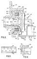
- connector component 12 actually is a panel 14 having an elongate opening 16 through which a mating end 18 of the first connector 10 is inserted.
- the first connector assembly 10 includes a main connector part 20, and a subassembly 22.
- the subassembly 22 includes a housing 24 which mounts a ferrite filter block 26 through which tails 28 of a plurality of terminals project for insertion into appropriate holes in a printed circuit board 30 (Fig. 2), whereby the terminals tails 28 are soldered to appropriate circuit traces on the board or in the holes.
- Main connector part 20 includes a die cast housing 32 mounted to printed circuit board 30 by appropriate fastening means 34 (Fig. 2).
- the terminals have contact pins 36 projecting into mating end 18 of the connector 10, whereby the contact pins are engageable with complementary terminals (not shown) of an appropriate mating electrical connector inserted into mating end 18 in the direction of arrow "A".
- the contact pins of the terminals project through a flexible capacitor filter circuit 38 mounted to the back side of housing 32.
- the contact pins also project through a pair of seal blocks 40 (Fig. 1) which sandwich a base wall 42 of housing 32.
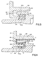
- the invention herein is directed to a sealing system between the first connector 10 and connector component 12 (panel 14) and which includes an environmental seal, generally designated 44, along with a radio frequency seal, generally designated 46. More particularly, referring to Figs. 3 and 4 in conjunction with Figs. 1 and 2, environmental seal 44 is provided by a seal-receiving channel 48 in housing 32, the channel being defined by mating end 18 and a forwardly projecting peripheral flange 49 of the housing. A resilient seal 50 is disposed within channel 48.
- the seal is generally U-shaped in cross-section to define a pair of legs 50a which form a sealing groove 52 therebetween.
- the sealing groove has a given width and a given depth of desired dimensions. Groove 52 and seal 50 surround mating end 18 of the connector assembly.
- Environmental seal 44 further includes a sealing lip 54 projecting rearwardly of panel 14 for insertion into sealing groove 52 along a mating axis which coincides with the mating direction "A" of main connector part 20 with its complementary connector.
- Fig. 2 and Fig. 3 show sealing lip 54 about to be inserted into sealing groove 52 of seal 50. This is the unmated condition of the environmental seal corresponding to the unmated condition of connector assembly 10 with connector component 12 (i.e. panel 14). It can be seen that the width of sealing lip 54 is greater than the width of sealing groove 52.
- Fig. 2 and Fig. 4 show sealing lip 54 inserted into sealing groove 52 and, with particular reference to Fig. 4, it can be seen that the sealing lip has compressed legs 50a of seal 50 in a direction normal or perpendicular to the insertion direction of the sealing lip, i.e. normal to mating axis "A". It also can be seen that the sealing lip has a length relative to the depth of the sealing groove such that the distal edge of the sealing lip is spaced from the bottom of the groove in fully mated condition. As a result, only sealing forces normal to the mating axis are effected between sealing lip 54 and sealing groove 52, as represented by arrows "B" in Fig. 4.
- radio frequency seal 46 is provided by a plurality of point contacts 60 formed along the entire distal edge of flange 49 of connector housing 32. It can be seen in Fig. 5 that point contacts 60 are arranged in rows, with the point contacts in adjacent rows being offset or alternating lengthwise of the edge of flange 49. The point contacts are located for engagement with a surface area 62 on the back side of panel 14, between sealing lip 54 and a further rearwardly projecting flange 64 of the panel.
- Fig. 2 and Fig. 3 show point contacts 60 and surface area 62 out of engagement. This represents the unmated condition of the radio frequency seal.
- the bottom half of Fig. 2 and Fig. 4 show point contacts 60 in abutting engagement with surface area 62. This represents the mated condition of the radio frequency seal corresponding to the mated condition of first connector 10 and connector component 12 (panel 14).
- the panel like housing 32, be of a die cast material, such as a magnesium casting. Therefore, point contacts 60 establish positive commoning between the connector housing and the panel surrounding the mating end 18 of connector 20 which projects through aperture 16 in the panel.
- the invention also contemplates the provision of a labyrinth path through radio frequency seal 44 (i.e. contact points 60) to enhance the protection capabilities of the seal against transmission therethrough of radio frequency or other interference waves.
- flange 49 which has contact points 60 along its distal edge
- sealing lip 54, flange 49 and flange 64 all overlap each other normal to the mating axis of the components.
- point contacts 60 are "hidden" in a deadend location between sealing lip 54 and flange 64.
- a labyrinth path c-c is provided to prevent direct interference waves from passing through the radio frequency seal.
- the interference waves must pass around flange 64, then around flange 49, and then around sealing lip 54 in order to flow through the interfacing area between main connector part 20 and connector component 12 (panel 14) effectively increasing the aspect ratio of the mating interface.
- the labyrinth is a redundant signal attenuation feature which dramatically increases the path length vs. the path width for EMI/RFI signals trying to transit across the interface.
Landscapes
- Connector Housings Or Holding Contact Members (AREA)
Claims (7)
- Verbinderanordnung mit folgenden Merkmalen:dadurch gekennzeichnet, daßein erster elektrischer Verbinder (10) ist mit einer anderen Verbinderkomponente (12) oder einer Tafel (14) oder dergleichen zusammenfügbar,der erste Verbinder (10) umfaßt ein Gehäuse (32) mit einem Paarungsende (18) und einem Dichtungsaufnahmekanal (48) undeine elastische Dichtung (50) wird in den Kanal (48) aufgenommen, wobei die andere Verbinderkomponente (12) oder Tafel (14) eine Dichtlippe (54) umfaßt, die in den Kanal (48) einsetzbar ist, wenn der Verbinder (10) und die andere Verbinderkomponente (12) oder Tafel (14) entlang einer Paarungsachse (A) zusammengefügt werden,die Dichtung (50) eine Dichtnut (52) mit einer gegebenen Breite und einer gegebenen Tiefe umfaßt,die Dichtlippe (54) eine Breite, die größer ist als die Breite der Dichtnut (52), und eine solche Länge relativ zur Tiefe der Dichtnut (52) aufweist, daß die Lippe (54) von dem Boden der Nut (52) beabstandet ist, wenn der erste Verbinder (10) und die Verbinderkomponente (12) oder Tafel (14) in einem zusammengefügten Zustand sind, wodurch nur Dichtungskräfte, die senkrecht zur Paarungsachse (A) ausgerichtet sind, zwischen der Dichtlippe (54) und der Dichtnut (52) wirksam werden.
- Verbinderanordnung nach Anspruch 1,
dadurch gekennzeichnet, daß die elastische Dichtung (50) im wesentlichen einen U-förmigen Querschnitt aufweist, um zwei Schenkel (50a) zu bilden, welche die Dichtnut (52) einschließen. - Verbinderanordnung nach Anspruch 1,bei der komplementäre ineinandergreifende Anschlagseinrichtungen (60, 62) zwischen der Verbinderanordnung und der Verbinderkomponente vorgesehen sind, um die Eindringtiefe der Dichtlippe (54) in der Dichtnut (52) zu begrenzen, so daßdie Lippe von dem Boden der Nut beabstandet bleibt, wenn sich der erste Verbinder und die andere Verbinderkomponente (12) oder Tafel (14) im zusammengefügten Zustand befinden.
- Verbinderanordnung nach Anspruch 3,
dadurch gekennzeichnet, daß die komplementären ineinandergreifenden Anschlagseinrichtungen (60, 62) leitendes Material aufweisen und ein Muster von Punktkontakten (60) umfassen, um dazwischen eine Hochfrequenz-Dichtung (46) zu bilden. - Verbinderanordnung nach Anspruch 4,
dadurch gekennzeichnet, daß sich die komplementären ineinandergreifenden Anschlagseinrichtungen (60, 62) im wesentlichen im Ganzen um das Paarungsende (18) des Gehäuses (32) des ersten Verbinders (10) erstrecken. - Verbinderanordnung nach Anspruch 4,
dadurch gekennzeichnet, daß die Dichtlippe (54) durch einen ersten peripheren Flansch gebildet wird, der von der anderen Verbinderkomponente (12) oder Tafel (14) zum Verbinder (10) hervorragt, und daß die komplementären ineinandergreifenden Anschlagseinrichtungen (60, 62) einen zweiten peripheren Flansch (49) umfassen, der von dem ersten Verbinder (10) zur anderen Verbinderkomponente (12) oder Tafel (14) hervorragt, wobei die Flansche (49, 54, 64) den jeweils anderen senkrecht zur Paarungsachse (A) überlappen, um einen labyrinthartigen Weg durch einen Übergangsbereich bilden, der diese Hochfrequenz-Dichtung (46) umfaßt. - Verbinderanordnung nach Anspruch 6,
dadurch gekennzeichnet, daß die Lippe (54) an einer Seite des zweiten peripheren Flansches (49) angeordnet ist, und daß die Verbinderkomponente (12) einen dritten peripheren Flansch (64) umfaßt, der von der Verbinderkomponente (12) oder Tafel (14) zum ersten Verbinder (19) an einer gegenüberliegenden Seite des zweiten peripheren Flansches (49) hervorragt.
Applications Claiming Priority (2)
| Application Number | Priority Date | Filing Date | Title |
|---|---|---|---|
| US994006 | 1992-12-21 | ||
| US07/994,006 US5277610A (en) | 1992-12-21 | 1992-12-21 | Sealing system for electrical connectors |
Publications (3)
| Publication Number | Publication Date |
|---|---|
| EP0603740A2 EP0603740A2 (de) | 1994-06-29 |
| EP0603740A3 EP0603740A3 (de) | 1995-11-15 |
| EP0603740B1 true EP0603740B1 (de) | 1999-10-06 |
Family
ID=25540189
Family Applications (1)
| Application Number | Title | Priority Date | Filing Date |
|---|---|---|---|
| EP93120265A Expired - Lifetime EP0603740B1 (de) | 1992-12-21 | 1993-12-16 | Abdichtsystem für elektrische Verbinder |
Country Status (6)
| Country | Link |
|---|---|
| US (1) | US5277610A (de) |
| EP (1) | EP0603740B1 (de) |
| JP (1) | JPH0831344B2 (de) |
| KR (1) | KR0128484B1 (de) |
| DE (1) | DE69326675T2 (de) |
| SG (1) | SG43828A1 (de) |
Families Citing this family (37)
| Publication number | Priority date | Publication date | Assignee | Title |
|---|---|---|---|---|
| JP2574806Y2 (ja) * | 1993-11-26 | 1998-06-18 | 住友電装株式会社 | コネクタ |
| JP2964443B2 (ja) * | 1994-08-30 | 1999-10-18 | 矢崎総業株式会社 | コネクタの防水パッキン |
| FR2723893A1 (fr) * | 1994-08-30 | 1996-03-01 | Valeo Vision | Dispositif d'eclairage ou de signalisation de vehicule automobile comportant un ensemble de connecteurs a moyens d'etancheite perfectionnes |
| US5589119A (en) * | 1994-12-22 | 1996-12-31 | New Southland, Inc. | Silicone elastomer seals for molded plastic parts |
| DE19533723B4 (de) * | 1995-09-12 | 2005-05-25 | The Whitaker Corp., Wilmington | Anordnung mit einem zweiteiligen Gehäuse und mindestens einem Steckeranschluß, sowie Verfahren zur Herstellung einer solchen Anordnung |
| DE19638590C1 (de) * | 1996-09-20 | 1998-03-05 | Delphi Automotive Systems Gmbh | Zweiteilige elektrische Verbindung, insbesondere für Kraftfahrzeuge |
| JP3570481B2 (ja) * | 1998-05-28 | 2004-09-29 | 住友電装株式会社 | パネル取り付けコネクタ |
| DE19958808A1 (de) * | 1999-12-07 | 2001-06-21 | Bayerische Motoren Werke Ag | Beleuchtungseinrichtung für ein Fahrzeug |
| KR100346461B1 (ko) * | 2000-10-26 | 2002-07-27 | 현대자동차주식회사 | 자동차용 방수 커넥터 구조 |
| JP2002318162A (ja) * | 2001-02-01 | 2002-10-31 | Canon Inc | 異常の検知方法および保護装置、並びに、温度の推定方法および推定装置 |
| US7503790B2 (en) * | 2007-07-03 | 2009-03-17 | Rockwell Automation Technologies, Inc. | Industrial automation input output module with elastomeric sealing |
| US8025530B2 (en) * | 2008-07-14 | 2011-09-27 | Savi Technology, Inc. | Method and apparatus involving a housing with a sealed electrical connector |
| JP5467850B2 (ja) | 2009-12-03 | 2014-04-09 | 矢崎総業株式会社 | L字型コネクタ |
| US11545781B2 (en) | 2010-03-03 | 2023-01-03 | Ex Company Limited | Connector and connection device for electronic equipment |
| CN107069274B (zh) * | 2010-05-07 | 2020-08-18 | 安费诺有限公司 | 高性能线缆连接器 |
| US8241051B2 (en) * | 2010-07-22 | 2012-08-14 | Tyco Electronics Corporation | System and method for sealing a connector |
| JP2013114830A (ja) * | 2011-11-28 | 2013-06-10 | Tyco Electronics Japan Kk | 防水型コネクタ、防水型コネクタの実装構造及び実装方法 |
| WO2013130692A2 (en) | 2012-03-01 | 2013-09-06 | Molex Incorporated | Panel connector |
| DE102013103116B3 (de) * | 2013-03-27 | 2014-09-18 | Semikron Elektronik Gmbh & Co. Kg | Leistungshalbleitermodul und Verfahren zur Herstellung eines Leistungshalbleitermoduls |
| DE102014015148B4 (de) * | 2014-10-13 | 2018-11-29 | Sumitomo Wiring Systems, Ltd. | Ladeverbinder und Verfahren zum Montieren desselben |
| DE102014222553A1 (de) * | 2014-11-05 | 2016-05-12 | BSH Hausgeräte GmbH | Haushaltsgerät mit einer Netzanschlußbuchse |
| US10306793B2 (en) | 2015-09-14 | 2019-05-28 | CommScope Connectivity Belgium BVBA | Longitudinal radial seal |
| DE102016105497B3 (de) * | 2016-03-23 | 2017-08-03 | Lisa Dräxlmaier GmbH | Elektrischer Steckverbinder |
| CN107293895B (zh) * | 2016-04-11 | 2019-07-26 | 富士康(昆山)电脑接插件有限公司 | 电连接器及其制造方法 |
| DE102016122397B4 (de) * | 2016-11-21 | 2020-08-06 | Amphenol-Tuchel Electronics Gmbh | Steckverbinderpanel für den Einbau in ein Gerätegehäuse sowie Gerät mit einem Gerätegehäuse mit diesem Steckverbinderpanel |
| EP3413403B1 (de) * | 2017-06-08 | 2021-12-15 | FRIWO Gerätebau GmbH | Adaptergehäuse mit fassung zum wasserdichten montieren einer stromversorgung auf einem gerät |
| JP7019147B2 (ja) * | 2018-05-09 | 2022-02-15 | 日本圧着端子製造株式会社 | 防水コネクタ及び機器ケースの防水構造 |
| CN211711038U (zh) * | 2019-12-09 | 2020-10-20 | 深之蓝(天津)水下智能科技有限公司 | 一种水下密封舱 |
| CN211417560U (zh) * | 2019-12-09 | 2020-09-04 | 深之蓝(天津)水下智能科技有限公司 | 一种水下密封舱 |
| CA3173691A1 (en) * | 2020-04-22 | 2021-10-28 | Sebastien Geoffroy | Pass-through connector for a battery pack, battery pack, and method for introducing at least one gas in a hermetically sealable casing for a battery pack |
| CN114554769B (zh) * | 2020-11-18 | 2024-03-22 | 英业达科技有限公司 | 服务器的密封方法 |
| JP2022149207A (ja) | 2021-03-25 | 2022-10-06 | 住友電装株式会社 | パネル取付型コネクタ |
| JP7706751B2 (ja) * | 2021-10-26 | 2025-07-14 | 株式会社アイエイアイ | コネクタ支持部材とアクチュエータ |
| JP2023112441A (ja) * | 2022-02-01 | 2023-08-14 | 株式会社オートネットワーク技術研究所 | 接続端子、コネクタ、及びコネクタ装置 |
| CN116154530B (zh) * | 2023-04-21 | 2023-06-20 | 东台正耀精密技术有限公司 | 一种h-mtd连接器 |
| CN117060146A (zh) * | 2023-08-30 | 2023-11-14 | 上海拜骋电器有限公司 | 电池包连接器防水结构及电池包 |
| DE102024204729A1 (de) * | 2024-05-23 | 2025-11-27 | Robert Bosch Gesellschaft mit beschränkter Haftung | Steckanordnung mit verbesserter Abdichtung |
Family Cites Families (6)
| Publication number | Priority date | Publication date | Assignee | Title |
|---|---|---|---|---|
| FR2412963A1 (fr) * | 1977-12-23 | 1979-07-20 | Alsthom Atlantique | Protection mecanique des connecteurs electriques d'ensembles electroniques de puissance refroidis par un hydrocarbure fluore |
| US4676575A (en) * | 1986-06-19 | 1987-06-30 | Amp Incorporated | Sealing member for bulkhead connector |
| DE3728456A1 (de) * | 1987-08-26 | 1989-03-30 | Bosch Gmbh Robert | Elektronisches schalt- und steuergeraet mit mehrreihiger steckerleiste |
| DE4101316C1 (de) * | 1991-01-18 | 1992-05-27 | Aloys Mennekes Anlagengesellschaft, 5942 Kirchhundem, De | |
| US5100335A (en) * | 1991-01-28 | 1992-03-31 | Thomas & Betts Corporation | Sealed electrical connector and seal ring therefor |
| JP2524095Y2 (ja) * | 1991-04-15 | 1997-01-29 | 住友電装株式会社 | 自動車エンジンの高圧接続部のキヤップ |
-
1992
- 1992-12-21 US US07/994,006 patent/US5277610A/en not_active Expired - Lifetime
-
1993
- 1993-12-09 JP JP5340749A patent/JPH0831344B2/ja not_active Expired - Lifetime
- 1993-12-16 EP EP93120265A patent/EP0603740B1/de not_active Expired - Lifetime
- 1993-12-16 DE DE69326675T patent/DE69326675T2/de not_active Expired - Fee Related
- 1993-12-16 SG SG1996001615A patent/SG43828A1/en unknown
- 1993-12-20 KR KR1019930028564A patent/KR0128484B1/ko not_active Expired - Fee Related
Also Published As
| Publication number | Publication date |
|---|---|
| JPH0831344B2 (ja) | 1996-03-27 |
| US5277610A (en) | 1994-01-11 |
| JPH06260240A (ja) | 1994-09-16 |
| DE69326675D1 (de) | 1999-11-11 |
| SG43828A1 (en) | 1997-11-14 |
| EP0603740A3 (de) | 1995-11-15 |
| DE69326675T2 (de) | 2000-05-25 |
| EP0603740A2 (de) | 1994-06-29 |
| KR0128484B1 (ko) | 1998-04-15 |
| KR940016998A (ko) | 1994-07-25 |
Similar Documents
| Publication | Publication Date | Title |
|---|---|---|
| EP0603740B1 (de) | Abdichtsystem für elektrische Verbinder | |
| EP0852899B1 (de) | Dichtungsanlage zur emv-isolierung | |
| US5311408A (en) | Electronic assembly with improved grounding and EMI shielding | |
| US7074084B2 (en) | Shielded blind-mate connector | |
| KR100635893B1 (ko) | 안정된 장착작업을 보장하는 단순한 구조를 갖는 커넥터 | |
| JPH07230853A (ja) | フィルタ付きの電気コネクタ組立体 | |
| US6033263A (en) | Electrically connector with capacitive coupling | |
| JP2010503154A (ja) | 静電気放電保護を有する電気コネクタ | |
| WO1998011630A1 (en) | Electrical connector | |
| US6984137B2 (en) | Electrical connector and electrical connector assembly | |
| EP1022812B1 (de) | Gefilterter Verbinder mit Ausrichtungvorrichtung für Anschlussende | |
| US5352995A (en) | Multipolar jack for electronic signal lines | |
| US20050101168A1 (en) | Connector with hermaphroditic center ground plane | |
| US6176728B1 (en) | Connecting device for large cable-to-card connectors | |
| US6739885B2 (en) | Filtered and shielded electrical connector | |
| JPH07101784B2 (ja) | シールドされたエンクロージャ組立体 | |
| US6349043B1 (en) | Apparatus for reducing electromagnetic emissions | |
| US5960136A (en) | Shielded fiber optic connector | |
| US20050142922A1 (en) | Electrical connector assembly | |
| KR970704328A (ko) | 전기커넥터 및 인쇄회로기판 | |
| CN116979248A (zh) | 天线装置 | |
| CN223488572U (zh) | 电力电子集成模块总成 | |
| US6146201A (en) | Electrical connector having a rear shielding member shielding tail sections of contact elements of the connector | |
| US5511994A (en) | Electrical connector having a device retaining means and a method of assembly thereof | |
| JP2785309B2 (ja) | コネクタ |
Legal Events
| Date | Code | Title | Description |
|---|---|---|---|
| PUAI | Public reference made under article 153(3) epc to a published international application that has entered the european phase |
Free format text: ORIGINAL CODE: 0009012 |
|
| AK | Designated contracting states |
Kind code of ref document: A2 Designated state(s): DE ES FR GB IT SE |
|
| PUAL | Search report despatched |
Free format text: ORIGINAL CODE: 0009013 |
|
| AK | Designated contracting states |
Kind code of ref document: A3 Designated state(s): DE ES FR GB IT SE |
|
| 17P | Request for examination filed |
Effective date: 19960308 |
|
| 17Q | First examination report despatched |
Effective date: 19980402 |
|
| GRAG | Despatch of communication of intention to grant |
Free format text: ORIGINAL CODE: EPIDOS AGRA |
|
| GRAG | Despatch of communication of intention to grant |
Free format text: ORIGINAL CODE: EPIDOS AGRA |
|
| GRAH | Despatch of communication of intention to grant a patent |
Free format text: ORIGINAL CODE: EPIDOS IGRA |
|
| ITF | It: translation for a ep patent filed | ||
| GRAH | Despatch of communication of intention to grant a patent |
Free format text: ORIGINAL CODE: EPIDOS IGRA |
|
| GRAA | (expected) grant |
Free format text: ORIGINAL CODE: 0009210 |
|
| AK | Designated contracting states |
Kind code of ref document: B1 Designated state(s): DE ES FR GB IT SE |
|
| PG25 | Lapsed in a contracting state [announced via postgrant information from national office to epo] |
Ref country code: SE Free format text: THE PATENT HAS BEEN ANNULLED BY A DECISION OF A NATIONAL AUTHORITY Effective date: 19991006 Ref country code: ES Free format text: THE PATENT HAS BEEN ANNULLED BY A DECISION OF A NATIONAL AUTHORITY Effective date: 19991006 |
|
| ET | Fr: translation filed | ||
| REF | Corresponds to: |
Ref document number: 69326675 Country of ref document: DE Date of ref document: 19991111 |
|
| PLBE | No opposition filed within time limit |
Free format text: ORIGINAL CODE: 0009261 |
|
| STAA | Information on the status of an ep patent application or granted ep patent |
Free format text: STATUS: NO OPPOSITION FILED WITHIN TIME LIMIT |
|
| 26N | No opposition filed | ||
| PGFP | Annual fee paid to national office [announced via postgrant information from national office to epo] |
Ref country code: GB Payment date: 20011102 Year of fee payment: 9 |
|
| PGFP | Annual fee paid to national office [announced via postgrant information from national office to epo] |
Ref country code: FR Payment date: 20011203 Year of fee payment: 9 |
|
| PGFP | Annual fee paid to national office [announced via postgrant information from national office to epo] |
Ref country code: DE Payment date: 20011228 Year of fee payment: 9 |
|
| REG | Reference to a national code |
Ref country code: GB Ref legal event code: IF02 |
|
| PG25 | Lapsed in a contracting state [announced via postgrant information from national office to epo] |
Ref country code: GB Free format text: LAPSE BECAUSE OF NON-PAYMENT OF DUE FEES Effective date: 20021216 |
|
| PG25 | Lapsed in a contracting state [announced via postgrant information from national office to epo] |
Ref country code: DE Free format text: LAPSE BECAUSE OF NON-PAYMENT OF DUE FEES Effective date: 20030701 |
|
| GBPC | Gb: european patent ceased through non-payment of renewal fee |
Effective date: 20021216 |
|
| PG25 | Lapsed in a contracting state [announced via postgrant information from national office to epo] |
Ref country code: FR Free format text: LAPSE BECAUSE OF NON-PAYMENT OF DUE FEES Effective date: 20030901 |
|
| REG | Reference to a national code |
Ref country code: FR Ref legal event code: ST |
|
| PG25 | Lapsed in a contracting state [announced via postgrant information from national office to epo] |
Ref country code: IT Free format text: LAPSE BECAUSE OF NON-PAYMENT OF DUE FEES;WARNING: LAPSES OF ITALIAN PATENTS WITH EFFECTIVE DATE BEFORE 2007 MAY HAVE OCCURRED AT ANY TIME BEFORE 2007. THE CORRECT EFFECTIVE DATE MAY BE DIFFERENT FROM THE ONE RECORDED. Effective date: 20051216 |