EP0603741A1 - Kabeltülle - Google Patents
Kabeltülle Download PDFInfo
- Publication number
- EP0603741A1 EP0603741A1 EP93120267A EP93120267A EP0603741A1 EP 0603741 A1 EP0603741 A1 EP 0603741A1 EP 93120267 A EP93120267 A EP 93120267A EP 93120267 A EP93120267 A EP 93120267A EP 0603741 A1 EP0603741 A1 EP 0603741A1
- Authority
- EP
- European Patent Office
- Prior art keywords
- wall
- cable
- piece
- opening
- bead
- Prior art date
- Legal status (The legal status is an assumption and is not a legal conclusion. Google has not performed a legal analysis and makes no representation as to the accuracy of the status listed.)
- Granted
Links
- XLYOFNOQVPJJNP-UHFFFAOYSA-N water Substances O XLYOFNOQVPJJNP-UHFFFAOYSA-N 0.000 claims abstract description 13
- 238000007789 sealing Methods 0.000 claims abstract description 12
- 239000011324 bead Substances 0.000 claims abstract description 9
- 238000009434 installation Methods 0.000 description 2
- 238000009413 insulation Methods 0.000 description 1
- 230000000149 penetrating effect Effects 0.000 description 1
- 230000035515 penetration Effects 0.000 description 1
Images

Classifications
-
- B—PERFORMING OPERATIONS; TRANSPORTING
- B60—VEHICLES IN GENERAL
- B60R—VEHICLES, VEHICLE FITTINGS, OR VEHICLE PARTS, NOT OTHERWISE PROVIDED FOR
- B60R16/00—Electric or fluid circuits specially adapted for vehicles and not otherwise provided for; Arrangement of elements of electric or fluid circuits specially adapted for vehicles and not otherwise provided for
- B60R16/02—Electric or fluid circuits specially adapted for vehicles and not otherwise provided for; Arrangement of elements of electric or fluid circuits specially adapted for vehicles and not otherwise provided for electric constitutive elements
- B60R16/0207—Wire harnesses
- B60R16/0215—Protecting, fastening and routing means therefor
- B60R16/0222—Grommets
-
- H—ELECTRICITY
- H02—GENERATION; CONVERSION OR DISTRIBUTION OF ELECTRIC POWER
- H02G—INSTALLATION OF ELECTRIC CABLES OR LINES, OR OF COMBINED OPTICAL AND ELECTRIC CABLES OR LINES
- H02G11/00—Arrangements of electric cables or lines between relatively-movable parts
-
- H—ELECTRICITY
- H02—GENERATION; CONVERSION OR DISTRIBUTION OF ELECTRIC POWER
- H02G—INSTALLATION OF ELECTRIC CABLES OR LINES, OR OF COMBINED OPTICAL AND ELECTRIC CABLES OR LINES
- H02G3/00—Installations of electric cables or lines or protective tubing therefor in or on buildings, equivalent structures or vehicles
- H02G3/22—Installations of cables or lines through walls, floors or ceilings, e.g. into buildings
Definitions
- the invention relates to a cable grommet for the passage of a cable through a component having an inner wall and an outer wall, which has an elastic jacket tube designed to enclose a cable, on which at one end a splash water sealing element which can be buttoned into an opening in the outer wall is formed.
- Cable grommets of the above type are required, for example, in motor vehicles in order to lead electrical lines from the A-pillars into the respective front door so that, for example, an electrical window regulator or a door locking mechanism can be supplied with electrical energy.
- the splash-water sealing element is buttoned into an opening on the outside of the A-pillar, which is intended for the cable duct, to prevent splash water from penetrating into the respective A-pillar.
- a penetration of noise into the vehicle interior through the opening in an inner wall which serves to lead through the cable is prevented by a radially slotted closure piece which is pushed onto the cable with the cable grommet after installation of the cable and then inserted into the inside opening.
- the locking pieces to be retrofitted do not provide optimal sound insulation because the radial slot is rarely acoustically sealed. This operation also requires that the relevant parts are kept ready during assembly.
- the invention is based on the problem of designing a cable grommet of the type mentioned at the outset in such a way that the best possible noise protection can be achieved with it and the assembly can be carried out as inexpensively as possible.
- the splash-water sealing element is connected via an elastic hose piece enclosing the cable to a closure piece which can be inserted into an opening in the inner wall.
- closure piece is formed in one piece with the splash water sealing element according to the invention, an individual part is saved, which reduces the assembly costs. Furthermore, the closure piece need not be radially slotted, since it no longer has to be applied subsequently to the cable, but rather reaches the cable together with the cable grommet. As a result, no gap which is not completely closed by a slot can arise in the opening, so that the acoustic seal is better than when separate closure pieces are subsequently applied.
- the closure piece could be buttoned into the opening of the inner wall, similar to the splash water sealing element.
- the closure piece for placement on the side of the inner wall facing the interior has a flange-like bead and the piece of hose is designed as a tension member holding the bead with pretension against the inner wall.
- Such a closure piece is particularly tight and tight against the inner wall.
- the closure piece for engaging in the opening of the inner wall has a truncated cone area.
- the piece of hose can be designed very differently. It is smooth on the inside, so that the cable can be inserted without problems, and is able to optimally fulfill its function as a tension member if, according to another development of the invention, the piece of hose is formed from a thin-walled tubular body and is formed on the outside of it and extends in the longitudinal direction of the piece of hose , beaded ribs.
- the closure piece is optimally designed if it has an inner body tapering in cross section to the free end for contacting the cable and an outer body with the flange-like bead for seating on the outside of the inner wall, and if the inner body and the outer body have a plurality of radial ribs are interconnected.
- FIG. 1 shows an outer wall 1 with an opening 2 and an inner wall 3 with one aligned with the opening 2 Opening 4.
- a splash water sealing element 5 of a cable grommet 6 is connected to the splash water sealing element 5 via a piece of hose 8 and in the opening 4 of the inner wall 3 sits.
- the closure piece 7 has a flange-like, circumferential bead 9 with which it rests against the side of the inner wall 3 facing the interior.
- the closure piece 7 engages with a truncated cone area 10 sealingly in the opening 4.
- the tube piece 8 is designed such that it prestresses the closure piece 7 in the assembled state shown in FIG. 1 in the direction of the splash-water sealing element 5.
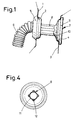
- Figures 2 and 4 show that the tube piece 8 consists of a thin-walled tubular body 11 and four bulge-like ribs 12 formed on the outside thereof.
- the half-section according to FIG. 2 further shows that the closure piece 7 has an inner body 13 and concentrically to it an outer body 14, these parts being supported against one another by radial ribs 15.
- the inner body 13 narrows toward the outlet of the cable grommet 6, so that a cable (not shown) running in the cable grommet 6 is tightly enclosed by the inner body 13.
- the outer body 14 has the bead 9, which bears against the inner wall 3, which was explained with reference to FIG. 1.
- FIG. 2 also shows a corrugated sheath 16 which is corrugated in the manner of a bellows and which surrounds the cable between the splash water sealing element 5 and a cap 17 at the other end of the cable grommet 6.
- the top view according to FIG. 3 shows that a total of four radial ribs 15 lead from the inner body 13 to the outer body 14.
Landscapes
- Engineering & Computer Science (AREA)
- Architecture (AREA)
- Civil Engineering (AREA)
- Structural Engineering (AREA)
- Mechanical Engineering (AREA)
- Installation Of Indoor Wiring (AREA)
- Insulating Bodies (AREA)
Abstract
Description
- Die Erfindung betrifft eine Kabeltülle zur Durchführung eines Kabels durch ein eine Innenwand und eine Außenwand aufweisendes Bauteil, welche ein zum Umschließen eines Kabels ausgebildetes, elastisches Hüllrohr hat, an welchem an einem Ende ein in eine Öffung der Außenwand einknöpfbares Spritzwasser-Dichtelement angeformt ist.
- Kabeltüllen der vorstehenden Art werden beispielsweise in Kraftfahrzeugen benötigt, um elektrische Leitungen aus den A-Säulen in die jeweilige Vordertüre zu führen, damit dort beispielsweise ein elektrischer Fensterheber oder ein Türverriegelungsmechanismus mit elektrischer Energie versorgt werden kann. Das Spritzwasser-Dichtelement wird bei der Montage in eine für die Kabeldurchführung vorgesehene Öffnung der Außenseite der A-Säule geknöpft, um ein Eindringen von Spritzwasser in die jeweilige A-Säule auszuschließen. Ein Eindringen von Geräuschen in den Fahrzeuginnenraum durch die der Kabeldurchführung dienende Öffnung in einer Innenwand verhindert man durch ein radial geschlitztes Verschlußstück, welches man nach der Montage des Kabels mit der Kabeltülle auf das Kabel aufschiebt und dann in die innenseitige Öffnung einsetzt.
- Die nachträglich zu montierenden Verschlußstücke stellen keinen optimalen Schallschutz dar, weil der radiale Schlitz akustisch selten dicht ist. Auch erfordert dieser Arbeitsgang bei der Montage ein Bereithalten der entsprechenden Teile.
- Der Erfindung liegt das Problem zugrunde, eine Kabeltülle der eingangs genannten Art so auszubilden, daß mit ihr ein möglichst guter Geräuschschutz zu erzielen ist und die Montage möglichst kostengünstig erfolgen kann.
- Dieses Problem wird erfindungsgemäß dadurch gelöst, daß das Spritzwasser-Dichtelement über ein das Kabel umschließendes, elastisches Schlauchstück mit einem in eine Öffnung der Innenwand einsetzbaren Verschlußstück verbunden ist.
- Dadurch, daß gemäß der Erfindung das Verschlußstück einstückig mit dem Spritzwasser-Dichtelement ausgebildet ist, wird ein Einzelteil eingespart, was die Montagekosten reduziert. Weiterhin braucht das Verschlußstück nicht radial geschlitzt zu sein, da es nicht mehr nachträglich auf das Kabel aufgebracht werden muß, sondern zusammen mit der Kabeltülle auf das Kabel gelangt. Dadurch kann in der Öffnung kein durch einen Schlitz nicht vollständig verschlossener Spalt entstehen, so daß die akustische Abdichtung besser ist als bei nachträglichem Aufbringen von separaten Verschlußstücken.
- Das Verschlußstück könnte ähnlich wie das Spritzwasser-Dichtelement in die Öffnung der Innenwand eingeknöpft werden. Besonders einfach und rasch ist es jedoch zu montieren, wenn gemäß einer Weiterbildung der Erfindung das Verschlußstück zum Aufsetzen auf die dem Innenraum zugewandten Seite der Innenwand einen flanschartigen Wulst hat und das Schlauchstück als den Wulst mit Vorspannung gegen die Innenwand haltendes Zugglied ausgebildet ist. Ein solches Verschlußstück liegt zugleich besonders fest und dicht gegen die Innenwand an.
- Zur weiteren Verbesserung der akustischen Abdichtung trägt es bei, wenn das Verschlußstück zum Eingreifen in die Öffnung der Innenwand einen Kegelstumpfbereich hat.
- Das Schlauchstück kann sehr unterschiedlich gestaltet sein. Es ist auf seiner Innenseite glatt, so daß das Kabel problemlos eingeführt werden kann, und vermag seine Aufgabe als Zugglied optimal zu erfüllen, wenn gemäß einer anderen Weiterbildung der Erfindung das Schlauchstück aus einem dünnwandigen Rohrkörper und außenseitig auf diesem angeformten, in Längsrichtung des Schlauchstückes verlaufenden, wulstförmigen Rippen besteht.
- Das Verschlußstück ist optimal ausgebildet, wenn es konzentrisch zueinander einen zum freien Ende sich im Querschnitt verjüngenden Innenkörper zum Anlegen gegen das Kabel und einen Außenkörper mit dem flanschartigen Wulst zum Aufsitzen auf die Außenseite der Innenwand hat und wenn der Innenkörper und der Außenkörper durch mehrere radiale Rippen miteinander verbunden sind.
- Die Erfindung läßt zahlreiche Ausführungsformen zu. Zur weiteren Verdeutlichung ihres Grundprinzips ist eine davon in der Zeichnung dargestellt und wird nachfolgend beschrieben. Diese zeigt in
- Fig. 1
- eine Ansicht der Kabeltülle in einem montierten Zustand,
- Fig. 2
- eine halbseitig geschnitten dargestellte Seitenansicht der Kabeltülle,
- Fig. 3
- eine Draufsicht auf die Kabeltülle,
- Fig. 4
- einen Schnitt durch die Kabeltülle entlang der Linie IV - IV in Figur 2.
- Die Figur 1 zeigt eine Außenwand 1 mit einer Öffnung 2 und eine Innenwand 3 mit einer zur Öffnung 2 fluchtenden Öffnung 4. In der Öffnung 2 der Außenwand 1 sitzt ein Spritzwasser-Dichtelement 5 einer Kabeltülle 6. Wichtig für die Erfindung ist ein Verschlußstück 7, welches über ein Schlauchstück 8 mit dem Spritzwasser-Dichtelement 5 verbunden ist und in der Öffnung 4 der Innenwand 3 sitzt. Zum Versperren der Öffnung 4 hat das Verschlußstück 7 einen flanschartigen, umlaufenden Wulst 9, mit dem es gegen die dem Innenraum zugewandte Seite der Innenwand 3 aufsitzt. Zusätzlich greift das Verschlußstück 7 mit einem Kegelstumpfbereich 10 dichtend in die Öffnung 4. Das Schlauchstück 8 ist so ausgebildet, daß es das Verschlußstück 7 im in Figur 1 dargestellten montierten Zustand in Richtung des Spritzwasser-Dichtelementes 5 vorspannt.
- Die Figuren 2 und 4 lassen erkennen, daß das Schlauchstück 8 aus einem dünnwandigen Rohrkörper 11 und vier außenseitig an diesem angeformten, wulstartigen Rippen 12 besteht. Der Halbschnitt gemäß Figur 2 zeigt weiterhin, daß das Verschlußstück 7 einen Innenkörper 13 und konzentrisch dazu einen Außenkörper 14 hat, wobei diese Teile sich durch radiale Rippen 15 gegeneinander abstützen. Der Innenkörper 13 verengt sich zum Auslaß der Kabeltülle 6 hin, so daß ein in der Kabeltülle 6 verlaufendes, nicht gezeigtes Kabel von dem Innenkörper 13 dicht umschlossen wird. Der Außenkörper 14 hat den Wulst 9, der gegen die Innenwand 3 anliegt, was anhand der Figur 1 erläutert wurde.
- In Figur 2 ist weiterhin ein nach Art eines Faltenbalges gewelltes Hüllrohr 16 dargestellt, welches das Kabel zwischem dem Spritzwasser-Dichtelement 5 und einer Kappe 17 am anderen Ende der Kabeltülle 6 umgibt.
- Die Draufsicht gemäß Figur 3 zeigt, daß vom Innenkörper 13 insgesamt vier radiale Rippen 15 zum Außenkörper 14 führen.
Claims (5)
- Kabeltülle zur Durchführung eines Kabels durch ein eine Innenwand und eine Außenwand aufweisendes Bauteil, welche ein zum Umschließen eines Kabels ausgebildetes, elastisches Hüllrohr hat, an welchem an einem Ende ein in eine Öffung der Außenwand einknöpfbares Spritzwasser-Dichtelement angeformt ist, dadurch gekennzeichnet, daß das Spritzwasser-Dichtelement (5) über ein das Kabel umschließendes, elastisches Schlauchstück (8) mit einem in eine Öffnung (4) der Innenwand (3) einsetzbaren Verschlußstück (7) verbunden ist.
- Kabeltülle nach Anspruch 1, dadurch gekennzeichnet, daß das Verschlußstück (7) zum Aufsetzen auf die dem Innenraum zugewandten Seite der Innenwand (3) einen flanschartigen Wulst (9) hat und das Schlauchstück (8) als den Wulst (9) mit Vorspannung gegen die Innenwand (3) haltendes Zugglied ausgebildet ist.
- Kabeltülle nach Anspruch 2, dadurch gekennzeichnet, daß das Verschlußstück (7) zum Eingreifen in die Öffnung (4) der Innenwand (3) einen Kegelstumpfbereich (10) hat.
- Kabeltülle nach zumindest einem der vorangehenden Ansprüche, dadurch gekennzeichnet, daß das Schlauchstück (8) aus einem dünnwandigen Rohrkörper (11) und außenseitig auf diesem angeformten, in Längsrichtung des Schlauchstückes (8) verlaufenden, wulstförmigen Rippen (12) besteht.
- Kabeltülle nach zumindest einem der vorangehenden Ansprüche, dadurch gekennzeichnet, daß das Verschlußstück (7) konzentrisch zueinander einen zum freien Ende sich im Querschnitt verjüngenden Innenkörper (13) zum Anlegen gegen das Kabel und einen Außenkörper (14) mit dem flanschartigen Wulst (9) zum Aufsitzen auf die Außenseite der Innenwand (3) hat und daß der Innenkörper (13) und der Außenkörper (14) durch mehrere radiale Rippen (15) miteinander verbunden sind.
Applications Claiming Priority (2)
| Application Number | Priority Date | Filing Date | Title |
|---|---|---|---|
| DE4243557A DE4243557A1 (de) | 1992-12-22 | 1992-12-22 | Kabeltülle |
| DE4243557 | 1992-12-22 |
Publications (2)
| Publication Number | Publication Date |
|---|---|
| EP0603741A1 true EP0603741A1 (de) | 1994-06-29 |
| EP0603741B1 EP0603741B1 (de) | 1997-10-29 |
Family
ID=6476175
Family Applications (1)
| Application Number | Title | Priority Date | Filing Date |
|---|---|---|---|
| EP93120267A Expired - Lifetime EP0603741B1 (de) | 1992-12-22 | 1993-12-16 | Kabeltülle |
Country Status (2)
| Country | Link |
|---|---|
| EP (1) | EP0603741B1 (de) |
| DE (2) | DE4243557A1 (de) |
Cited By (7)
| Publication number | Priority date | Publication date | Assignee | Title |
|---|---|---|---|---|
| FR2725565A1 (fr) * | 1994-10-11 | 1996-04-12 | Peugeot | Dispositif de montage d'un faisceau de conducteurs electriques |
| FR2730785A1 (fr) * | 1995-02-17 | 1996-08-23 | Peugeot | Gaine de protection souple en caoutchouc pour assurer le passage d'un faisceau electrique ou d'un conduit |
| EP0882922A1 (de) * | 1997-06-04 | 1998-12-09 | Sumitomo Wiring Systems, Ltd. | Dichtungstülle mit Mittel zur Erzeugung von Wassertropfen |
| EP1036711A2 (de) | 1999-03-16 | 2000-09-20 | Volkswagen Aktiengesellschaft | Wanddurchführung für strangförmige Körper |
| FR2815482A1 (fr) * | 2000-10-12 | 2002-04-19 | C F Gomma Barre Thomas | Gaine de protection souple pour assurer le passage a travers une ouverture d'une cloison mince |
| DE102012005171A1 (de) * | 2012-03-16 | 2013-09-19 | Eduard Hueck Gmbh & Co. Kg | Hohlprofilanordnung |
| CN109314381A (zh) * | 2016-06-24 | 2019-02-05 | 住友电装株式会社 | 护线套以及线束 |
Families Citing this family (7)
| Publication number | Priority date | Publication date | Assignee | Title |
|---|---|---|---|---|
| JPH08273465A (ja) * | 1995-03-28 | 1996-10-18 | Sumitomo Wiring Syst Ltd | グロメットおよび該グロメットの検査装置 |
| JP3629309B2 (ja) * | 1995-09-05 | 2005-03-16 | アルプス電気株式会社 | 薄膜磁気ヘッド |
| FR2766023B1 (fr) * | 1997-07-11 | 1999-10-01 | Peugeot | Gaine de protection souple pour assurer le passage d'un faisceau electrique entre deux parties d'une installation telle qu'un vehicule automobile |
| DE19904549C2 (de) * | 1999-02-04 | 2003-03-27 | Bayerische Motoren Werke Ag | Durchführungsteil für mindestens ein Kabel, einen Seilzug oder dergleichen |
| FR2793082B1 (fr) * | 1999-04-30 | 2001-05-25 | Renault | Joint d'etancheite pour une traversee de paroi et assemblage obtenu avec ce joint |
| DE10225164A1 (de) * | 2002-06-06 | 2003-12-18 | Volkswagen Ag | Tülle für Leitungsdurchführungen |
| DE10342082A1 (de) * | 2003-09-10 | 2005-04-07 | Volkswagen Ag | Leitungsdurchführung von einem Fahrzeugkarosserie-Hohlteil in den Fahrzeuginnenraum und Stecker dafür |
Citations (5)
| Publication number | Priority date | Publication date | Assignee | Title |
|---|---|---|---|---|
| FR2335972A1 (fr) * | 1975-12-16 | 1977-07-15 | Bayerische Motoren Werke Ag | Dispositif de fixation pour une gaine de cables, torons ou organes similaires |
| FR2569911A1 (fr) * | 1984-08-28 | 1986-03-07 | Lisa Draxlmaier | Guide-cables etanche a l'humidite |
| US4685173A (en) * | 1986-07-07 | 1987-08-11 | Chrysler Motors Corporation | Grommet with angularly positionable tubular portion |
| DE3916468C1 (en) * | 1989-05-20 | 1990-05-10 | Audi Ag, 8070 Ingolstadt, De | Wiring feed through for motor vehicle - provides channel between door post on bodywork side and end face of door hinge |
| FR2642497A1 (fr) * | 1989-01-10 | 1990-08-03 | Peugeot | Joint annulaire d'etancheite assurant la jonction etanche d'un element tubulaire et d'une paroi traversee par cet element |
-
1992
- 1992-12-22 DE DE4243557A patent/DE4243557A1/de not_active Withdrawn
-
1993
- 1993-12-16 EP EP93120267A patent/EP0603741B1/de not_active Expired - Lifetime
- 1993-12-16 DE DE59307603T patent/DE59307603D1/de not_active Expired - Fee Related
Patent Citations (5)
| Publication number | Priority date | Publication date | Assignee | Title |
|---|---|---|---|---|
| FR2335972A1 (fr) * | 1975-12-16 | 1977-07-15 | Bayerische Motoren Werke Ag | Dispositif de fixation pour une gaine de cables, torons ou organes similaires |
| FR2569911A1 (fr) * | 1984-08-28 | 1986-03-07 | Lisa Draxlmaier | Guide-cables etanche a l'humidite |
| US4685173A (en) * | 1986-07-07 | 1987-08-11 | Chrysler Motors Corporation | Grommet with angularly positionable tubular portion |
| FR2642497A1 (fr) * | 1989-01-10 | 1990-08-03 | Peugeot | Joint annulaire d'etancheite assurant la jonction etanche d'un element tubulaire et d'une paroi traversee par cet element |
| DE3916468C1 (en) * | 1989-05-20 | 1990-05-10 | Audi Ag, 8070 Ingolstadt, De | Wiring feed through for motor vehicle - provides channel between door post on bodywork side and end face of door hinge |
Cited By (12)
| Publication number | Priority date | Publication date | Assignee | Title |
|---|---|---|---|---|
| FR2725565A1 (fr) * | 1994-10-11 | 1996-04-12 | Peugeot | Dispositif de montage d'un faisceau de conducteurs electriques |
| EP0706915A1 (de) * | 1994-10-11 | 1996-04-17 | Automobiles Peugeot | Montage-Einrichtung für ein Bündel elektrischer Leiter |
| FR2730785A1 (fr) * | 1995-02-17 | 1996-08-23 | Peugeot | Gaine de protection souple en caoutchouc pour assurer le passage d'un faisceau electrique ou d'un conduit |
| EP0882922A1 (de) * | 1997-06-04 | 1998-12-09 | Sumitomo Wiring Systems, Ltd. | Dichtungstülle mit Mittel zur Erzeugung von Wassertropfen |
| US6081964A (en) * | 1997-06-04 | 2000-07-04 | Sumitomo Wiring Systems, Ltd. | Grommet with a groove for channelizing water drips |
| CN1068983C (zh) * | 1997-06-04 | 2001-07-25 | 住友电装株式会社 | 带有用于渠化水滴的沟槽的套管 |
| EP1036711A2 (de) | 1999-03-16 | 2000-09-20 | Volkswagen Aktiengesellschaft | Wanddurchführung für strangförmige Körper |
| FR2815482A1 (fr) * | 2000-10-12 | 2002-04-19 | C F Gomma Barre Thomas | Gaine de protection souple pour assurer le passage a travers une ouverture d'une cloison mince |
| DE102012005171A1 (de) * | 2012-03-16 | 2013-09-19 | Eduard Hueck Gmbh & Co. Kg | Hohlprofilanordnung |
| DE102012005171B4 (de) * | 2012-03-16 | 2016-09-01 | Hueck Gmbh & Co. Kg | Hohlprofilanordnung |
| CN109314381A (zh) * | 2016-06-24 | 2019-02-05 | 住友电装株式会社 | 护线套以及线束 |
| CN109314381B (zh) * | 2016-06-24 | 2020-11-20 | 住友电装株式会社 | 护线套以及线束 |
Also Published As
| Publication number | Publication date |
|---|---|
| DE4243557A1 (de) | 1994-06-23 |
| DE59307603D1 (de) | 1997-12-04 |
| EP0603741B1 (de) | 1997-10-29 |
Similar Documents
| Publication | Publication Date | Title |
|---|---|---|
| DE4109206C1 (de) | ||
| EP0603741A1 (de) | Kabeltülle | |
| WO2013050180A2 (de) | Kabeldurchführung und verfahren zur montage einer kabeldurchführung | |
| AT519366B1 (de) | Anschlussgehäuse und anschlusssystem | |
| DE29801104U1 (de) | Gasgenerator | |
| EP1888374B1 (de) | Abdichtelement zur abdichtung eines strangförmigen körpers in einem durchbruch einer wand | |
| EP1648067B1 (de) | Kühl- und/oder Gefriergerät mit Dichtelement | |
| EP0305723B1 (de) | Mauerdurchführung für Kabel, Leitungen, Rohre oder dgl | |
| DE10332035B4 (de) | Dichtungstülle für eine Leitungsdurchführung in einer Wandung | |
| DE19801125A1 (de) | Airbagmodul | |
| DE69501674T2 (de) | Abdichtende Wanddurchführung | |
| DE10358002A1 (de) | Dichtungstülle | |
| DE10349440B4 (de) | Dichte Wanddurchführung mit Zugentlastung | |
| EP3790134A1 (de) | Kabeleinführung | |
| EP3544132B1 (de) | Axial fixierbare dichtungsanordnung für eine kabeldurchführung | |
| WO2008058581A2 (de) | Dichtungsanordnung zur abdichtung einer durchgangsöffnung und montageverfahren | |
| DE102008063582A1 (de) | Rohrschelle | |
| DE102008003350B4 (de) | Staubsauger mit einem Raum zur Aufnahme eines Motorgebläses | |
| DE19857340A1 (de) | Kabelverschraubung für Kabel mit Abschirmummantelung | |
| DE9015535U1 (de) | Batterie | |
| DE19718211A1 (de) | Umhüllung für Beifahrer-Airbag-Modul | |
| DE102013111653A1 (de) | Rohrbride für Verbrennungsluftrohre sowie Abgasrohrsystem | |
| DE102006029872B4 (de) | Leitungstülle zur Abdichtung von aus einem Motorraum in einen Wasserkasten eines Kraftfahrzeugs führenden Leitungen | |
| DE102005012313B3 (de) | Einrichtung für einen Einbauraum eines Fahrzeugs mit einem Verbindungskanal zwischen Öffnungen gegenüberliegender Wände | |
| DE10148324B4 (de) | Ventil zur Montage in einer Öffnung einer Radfelge |
Legal Events
| Date | Code | Title | Description |
|---|---|---|---|
| PUAI | Public reference made under article 153(3) epc to a published international application that has entered the european phase |
Free format text: ORIGINAL CODE: 0009012 |
|
| AK | Designated contracting states |
Kind code of ref document: A1 Designated state(s): DE FR GB |
|
| 17P | Request for examination filed |
Effective date: 19940819 |
|
| 17Q | First examination report despatched |
Effective date: 19951002 |
|
| GRAG | Despatch of communication of intention to grant |
Free format text: ORIGINAL CODE: EPIDOS AGRA |
|
| GRAH | Despatch of communication of intention to grant a patent |
Free format text: ORIGINAL CODE: EPIDOS IGRA |
|
| GRAH | Despatch of communication of intention to grant a patent |
Free format text: ORIGINAL CODE: EPIDOS IGRA |
|
| GRAA | (expected) grant |
Free format text: ORIGINAL CODE: 0009210 |
|
| AK | Designated contracting states |
Kind code of ref document: B1 Designated state(s): DE FR GB |
|
| ET | Fr: translation filed | ||
| GBT | Gb: translation of ep patent filed (gb section 77(6)(a)/1977) |
Effective date: 19971111 |
|
| REF | Corresponds to: |
Ref document number: 59307603 Country of ref document: DE Date of ref document: 19971204 |
|
| PLBE | No opposition filed within time limit |
Free format text: ORIGINAL CODE: 0009261 |
|
| STAA | Information on the status of an ep patent application or granted ep patent |
Free format text: STATUS: NO OPPOSITION FILED WITHIN TIME LIMIT |
|
| 26N | No opposition filed | ||
| REG | Reference to a national code |
Ref country code: GB Ref legal event code: IF02 |
|
| REG | Reference to a national code |
Ref country code: GB Ref legal event code: 746 Effective date: 20021101 |
|
| REG | Reference to a national code |
Ref country code: FR Ref legal event code: D6 |
|
| PGFP | Annual fee paid to national office [announced via postgrant information from national office to epo] |
Ref country code: FR Payment date: 20081212 Year of fee payment: 16 |
|
| PGFP | Annual fee paid to national office [announced via postgrant information from national office to epo] |
Ref country code: DE Payment date: 20081219 Year of fee payment: 16 |
|
| PGFP | Annual fee paid to national office [announced via postgrant information from national office to epo] |
Ref country code: GB Payment date: 20081216 Year of fee payment: 16 |
|
| GBPC | Gb: european patent ceased through non-payment of renewal fee |
Effective date: 20091216 |
|
| REG | Reference to a national code |
Ref country code: FR Ref legal event code: ST Effective date: 20100831 |
|
| PG25 | Lapsed in a contracting state [announced via postgrant information from national office to epo] |
Ref country code: FR Free format text: LAPSE BECAUSE OF NON-PAYMENT OF DUE FEES Effective date: 20091231 |
|
| PG25 | Lapsed in a contracting state [announced via postgrant information from national office to epo] |
Ref country code: DE Free format text: LAPSE BECAUSE OF NON-PAYMENT OF DUE FEES Effective date: 20100701 |
|
| PG25 | Lapsed in a contracting state [announced via postgrant information from national office to epo] |
Ref country code: GB Free format text: LAPSE BECAUSE OF NON-PAYMENT OF DUE FEES Effective date: 20091216 |