EP0603752A2 - Kühlmöbel - Google Patents
Kühlmöbel Download PDFInfo
- Publication number
- EP0603752A2 EP0603752A2 EP93120359A EP93120359A EP0603752A2 EP 0603752 A2 EP0603752 A2 EP 0603752A2 EP 93120359 A EP93120359 A EP 93120359A EP 93120359 A EP93120359 A EP 93120359A EP 0603752 A2 EP0603752 A2 EP 0603752A2
- Authority
- EP
- European Patent Office
- Prior art keywords
- compressor motor
- capsule element
- refrigerated cabinet
- compartment wall
- engine compartment
- Prior art date
- Legal status (The legal status is an assumption and is not a legal conclusion. Google has not performed a legal analysis and makes no representation as to the accuracy of the status listed.)
- Granted
Links
Images


Classifications
-
- F—MECHANICAL ENGINEERING; LIGHTING; HEATING; WEAPONS; BLASTING
- F25—REFRIGERATION OR COOLING; COMBINED HEATING AND REFRIGERATION SYSTEMS; HEAT PUMP SYSTEMS; MANUFACTURE OR STORAGE OF ICE; LIQUEFACTION SOLIDIFICATION OF GASES
- F25D—REFRIGERATORS; COLD ROOMS; ICE-BOXES; COOLING OR FREEZING APPARATUS NOT OTHERWISE PROVIDED FOR
- F25D23/00—General constructional features
- F25D23/006—General constructional features for mounting refrigerating machinery components
-
- F—MECHANICAL ENGINEERING; LIGHTING; HEATING; WEAPONS; BLASTING
- F25—REFRIGERATION OR COOLING; COMBINED HEATING AND REFRIGERATION SYSTEMS; HEAT PUMP SYSTEMS; MANUFACTURE OR STORAGE OF ICE; LIQUEFACTION SOLIDIFICATION OF GASES
- F25D—REFRIGERATORS; COLD ROOMS; ICE-BOXES; COOLING OR FREEZING APPARATUS NOT OTHERWISE PROVIDED FOR
- F25D23/00—General constructional features
- F25D23/12—Arrangements of compartments additional to cooling compartments; Combinations of refrigerators with other equipment, e.g. stove
-
- F—MECHANICAL ENGINEERING; LIGHTING; HEATING; WEAPONS; BLASTING
- F25—REFRIGERATION OR COOLING; COMBINED HEATING AND REFRIGERATION SYSTEMS; HEAT PUMP SYSTEMS; MANUFACTURE OR STORAGE OF ICE; LIQUEFACTION SOLIDIFICATION OF GASES
- F25B—REFRIGERATION MACHINES, PLANTS OR SYSTEMS; COMBINED HEATING AND REFRIGERATION SYSTEMS; HEAT PUMP SYSTEMS
- F25B2500/00—Problems to be solved
- F25B2500/12—Sound
Definitions
- the invention relates to a refrigerator, in particular a refrigerator, with a compressor motor and a compressor motor compartment, which has an engine compartment wall.
- the invention is based on the objective of designing a piece of refrigerated furniture, in particular a refrigerator, in a suitable, sound-reduced manner.
- the capsule element Due to the fact that the capsule element is open towards the rear, and thus also the compressor motor is exposed towards the rear, there are nevertheless surprisingly favorable thermal conditions a without the sound absorption would be significantly affected. This is because the fact that refrigeration units of this type are placed with the compressor motor toward the wall is advantageously used.
- the generally reverberant wall reflects sound waves emanating from the compressor motor on the exposed side back into the capsule element, which is also open to the wall, so that these sound waves are in turn largely dampened by the capsule element.
- the above and below described subject is not limited to refrigerated cabinets.
- the concept according to the invention can also be applied to other floor-standing devices, in particular furniture-standing devices with an electric motor that is similarly exposed to the outside.
- the capsule element has steps which lead to a different distance from the engine compartment wall. In this way, the effects that can be achieved by the enclosed air cushion between the flexible, thin wall of the capsule element and the engine compartment wall can be optimized.
- a special further development also provides that the capsule element extends laterally with a comparatively shallow depth to the compressor motor, but continues to open towards the rear of the refrigerated cabinet, preferably with an integral design. This is particularly important in that lateral emissions of the compressor motor, towards the side in which it is essentially exposed, meet the capsule element in reflection from a wall, in front of which, for example, the refrigeration cabinet is located, and are suitably absorbed or damped .
- the capsule element is perforated.
- the capsule element is dome-shaped in such a way that a substantial distance is formed between the capsule element and the compressor motor above the compressor motor and that an opening is formed in the capsule element in the region of the greatest distance to create a certain chimney effect.
- a chimney draft effect can be achieved through the dome-like design described. In this way, an essential natural convection can be generated, which can optimize the heat dissipation.
- the chimney formation can also extend relatively far upwards in the refrigeration cabinet, in order then to open up into the surroundings, which only improves the chimney draft.
- a condensate drip tray is formed integrated in the capsule element.
- a trough-like design is created in the capsule element, in which this condensed water can be collected.
- the water collecting trough preferably extends essentially above the compressor motor.
- FIG. 1 a Shown and described is first of all with reference to FIG. 1 a - only partially drawn - refrigerated cabinet 1 with a compressor motor 2 and a compressor motor chamber 4 (see, for example, FIG. 2).
- the compressor motor compartment 4 is divided by a capsule element 5, which consists of closed-cell polyethylene foam.
- the capsule element 5 is thin-walled, for example with a thickness of 2 mm.
- the capsule element surrounds the compressor motor 2, as it were, like a shell, but at different distances, as can be seen in detail from the sectional views in FIGS. 5 to 7.
- the distance to the engine compartment wall 3 is also different.
- the capsule element 5 is designed to be open to a rear side of the refrigerator, to which rear side the compressor motor 2 is also detached in the capsule element 5.
- a distance a on the back of the compressor motor 2 is chosen larger than a distance b on the top of the compressor motor 2.
- the distance a corresponds approximately to the distance c on the underside of the compressor motor 2 with respect to the clear one Distance to an engine compartment capsule itself, regardless of the vibration damper 6 still arranged below the compressor motor 2 and the mounting rails 7.
- the distance a on the rear side of the compressor motor 2 is selected differently, specifically in such a way that it is in corner areas 8, 9 of the compressor motor 2 down to a system on the compressor motor 2.
- the capsule element 5 While one side 10 of the compressor motor 2, where in particular cable connections and the like are located, the capsule element 5 is guided very close - at 11 - past the compressor motor 2, and is approximately rectangular in shape, an opposite one is angled with respect to the rear opening plane E. , provided at an angle alpha given extension of the capsule elements 5. This leads to a suitable absorption not only of the sound waves radiated directly from the compressor motor 2, but also to those sound waves which are reflected on a - not shown - reverberant wall, against which the refrigerator is placed in the installed state. Of particular importance in this context is the lateral extension, which is provided overall with reference number 12, which extends beyond the actual compressor engine compartment 4.
- this embodiment is optimized in such a way that suitable absorption of sound waves reflected in this direction can also take place.
- the capsule element 5 is provided with holes 13 which provide a direct connection to air spaces 14, 15 between the capsule element 5 and the engine compartment wall 2. It is not shown in detail that these air spaces 14 can also be subdivided by suitable bead formation, but can each be provided with a plurality of holes 13, so that overall a modified Helmholtz resonator results, as has already been described in detail above .
- a depth t here is substantially less than a depth t 'in the area of the actual compressor motor space 4.
- a water collecting trough 16 is formed on the upper side of the compressor motor 2, integrated in the capsule element 5. This is done simply by forming a bead, a circumferential U-bead 17 in the capsule element 5. Condensation or the like can drip into the water collecting trough 16, for example, through an opening 18 in the engine compartment wall 3 from above. The extent of the water collecting trough 16 can be much larger than shown in the drawing.
Landscapes
- Engineering & Computer Science (AREA)
- Chemical & Material Sciences (AREA)
- Combustion & Propulsion (AREA)
- Physics & Mathematics (AREA)
- Mechanical Engineering (AREA)
- Thermal Sciences (AREA)
- General Engineering & Computer Science (AREA)
- Compressor (AREA)
- Devices That Are Associated With Refrigeration Equipment (AREA)
- Liquid Crystal Substances (AREA)
- Cooling Or The Like Of Electrical Apparatus (AREA)
Abstract
Description
- Die Erfindung betrifft ein Kühlmöbel, insbesondere einen Kühlschrank, mit einem Kompressormotor und einem Kompressormotorraum, der eine Motorraumwandung aufweist.
- Derartige Kühlmöbel sind bekanntlich nahezu in jedem Haushalt anzutreffen. Zunehmend wird eine von dem Kompressormotor ausgehende Geräuschbildung als lästig empfunden. Hinzu kommt, daß im Zuge der Entwicklung von umweltfreundlicheren Kühlaggregaten der Geräuschpegel der Kühlaggregate tendenziell zunehmend ist.
- Es ist nun bereits im Stand der Technik vielfach bekannt, Geräuschquellen mit einem schallabsorbierenden Materials zu umgeben. Bspw. sei auf die CH-PS 439 569 hingewiesen. Gemäß dieser Druckschrift ist für ein Zentrifugalgebläse vorgeschlagen, die Wände des Gebläsegehäuses dickwandig mit einem schallabsorbierenden Material wie Polyurethanschaumstoff auszukleiden. Des weiteren ist es an sich bekannt, schalldämmende Verkleidungen in Kapselbauweise, mit mehrfach übereinander angeordneten Lagen, die zueinander gestuft sind, vorzusehen. Hierzu wird beispielsweise auf die eingetragenen Unterlagen des DE-GM 84 17 883 verwiesen, auch auf die DE-OS 27 58 041 und die eingetragenen Unterlagen des DE-GM 89 09 961. Für die Schalldämmung an einer Umwälzpumpe ist dagegen wieder vorgeschlagen worden, eine vollständige Kapslung mittels eines doppelschichtigen, unmittelbar anliegenden Schaumstoffteiles vorzunehmen, wozu auf die DE-OS 31 09 624 zu verweisen ist. Diese bekannten Schallminderungsmaßnahmen lassen sich jedoch bei einem Kühlmöbel der in Rede stehenden Art nur unter Inkaufnahme von gewissen Nachteilen verwirklichen. So reicht der zur Verfügung stehende Raum nicht aus, um in geeigneter Dicke schallabsorbierendes Material einbringen zu können. Es wären vollkommene Neukonstruktionen erforderlich. Weiterhin ist auch mit einer derartigen Auskleidung mit schallabsorbierendem Material eine nicht unerhebliche Wärmedämmung jeweils verbunden. Diese könnte zu Temperaturproblemen bezüglich des Kühlaggregates führen bzw. würde zusätzliche Kühlmaßnahmen, wie etwa einen Lüfter, erforderlich machen. Insgesamt würde hierdurch auch der Energieverbrauch des Kühlmöbels eher zunehmen als abnehmen.
- Ausgehend von dem vorbeschriebenen Stand der Technik liegt der Erfindung das Ziel zugrunde, ein Kühlmöbel, insbesondere einen Kühlschrank in geeigneter Weise schallreduziert auszubilden.
- Dieses Ziel ist beim Gegenstand des Anspruches 1 erreicht, wobei darauf abgestell ist, daß ein dünnwandiges Kapselelement aus geschlossenzelligem Schaumstoff zur Schallabsorption vorgesehen ist, das entsprechend einer Schale den Kompressormotor umgibt, im wesentlichen jeweils mit Abstand zu dem Kompressormotor und der Motorraumwandung, wobei das Kapselelement zu einer Rückseite des Kühlmöbels, zu welcher auch der Kompressormotor freiliegt, geöffnet ist. Erfindungsgemäß ist also erkannt worden, daß der begrenzte, zur Verfügung stehende Raum dadurch vorteilhaft ausgenutzt werden kann, daß gleichsam nach dem Prinzip einer abgehängten Wand eine Zwischenschale zwischen dem Kompressormotor und der Motorraumwandung vorgesehen wird, welche dadurch, daß sie aus geschlossenzelligem, dünnwandigem Schaumstoff besteht, durch ihre Schwingfähigkeit geeignet isf, störende Schallwellen zu dämpfen. Dadurch, daß das Kapselelement zur Rückseite hin geöffnet ist, und damit auch der Kompressormotor zur Rückseite hin freiliegt, stellen sich gleichwohl überraschend günstige thermische Bedingungen ein, ohne daß die Schalldämpfung wesentlich beeinträchtigt wäre. In vorteilhafter Weise wird nämlich die Tatsache ausgenutzt, daß derartige Kühlmöbel mit dem Kompressormotor jeweils zur Wand hin aufgestellt werden. Die in der Regel schallharte Wand reflektiert auf der freiliegenden Seite von dem Kompressormotor ausgehende Schallwellen in das zu der Wand gleichfalls offene Kapselelement hin zurück, so daß auch diese Schallwellen zu einem wesentlichen Teil wiederum durch das Kapselelement gedämpft werden. Darüber hinaus ist der vorstehzend und nachstehend beschriebene Gegenstand nicht auf Kühlmöbel zu beschränken. Auch bei sonstigen Standgeräten, insbesondere Möbel-Standgeräten mit einem Elektromotor, der in vergleichbarer Weise nach außen hin exponiert ist, läßt sich das erfindungsgemäße Konzept anwenden. In geeigneter Fortbildung ist vorgesehen, daß das Kapselelement Stufungen aufweist, die zu einem unterschiedlich Abstand zur Motorraumwandung führen. Es lassen sich so die Effekte, die durch das eingeschlossene Luftpolster zwischen der flexiblen, dünnen Wandung des Kapselelementes und der Motorraumwandung zu erzielen sind, optimieren. Eine besondere Weiterbildung sieht auch vor, daß das Kapselelement sich mit vergleichsweise geringer Tiefe seitlich zu dem Kompressormotor, jedoch weiterhin zu der Rückseite des Kühlmöbels hin geöffnet, bei bevorzugt integraler Ausführung, forterstreckt. Dies hat insbesondere dahingehend Bedeutung, daß auch seitliche Abstrahlungen des Kompressormotors, zu der Seite hin, in der er im wesentlichen freiliegt, in Reflexion von einer Wand, vor welcher etwa das Kühlmöbel steht, wieder auf das Kapselelement treffen und so geeignet absorbiert oder gedämpft werden. In weiterer Fortbildung ist auch vorgesehen, daß das Kapselelement gelocht ist. Es ergibt sich damit gleichsam eine Lochwandung flexibler Natur. In weiterer bevorzugter Fortbildung ist hierzu auch vorgesehen, daß in dem Kapselelement in Zusammenwirkung mit der Motorraumwandung durch Wulstbildung oder dgl. im wesentlichen geschlossene Kammern gebildet sind, welche jeweils mehrfach durch lochartige Öffnungen mit der Umgebung in unmittelbarer Verbindung stehen. So lassen sich eine Mehrzahl von Helmholtz-resonatorartigen Räumen zwischen der Motorraumwandung und dem Kapselelement erreichen. Im Unterschied zu dem "klassischen" Helmholtz-Resonator sind jedoch die Wände des durch das Kapselelement eingeschlossenen Luftraumes flexibel und ist der Luftraum über eine Mehrzahl von Öffnungen an die Umgebung angebunden. Hierin wird auch ein eigenständiges akustisches Schalldämpfungsprinzip gesehen, das für sich Bedeutung hat. In weiterer bevorzugter Ausgestaltung ist auch vorgesehen, daß das Kapselelement domartig ausgebildet ist, derart, daß oberhalb des Kompressormotors ein wesentlicher Abstand zwischen dem Kapselelement und dem Kompressormotor ausgebildet ist und daß im Bereich des größten Abstandes eine Öffnung in dem Kapselelement ausgebildet ist, zur Schaffung einer gewissen Kaminwirkung. Für den Fall, daß - jedenfalls bei besonderen Anwendungsfällen - eine gewisse thermische Last noch abzuführen ist, ist durch die beschriebene domartige Ausbildung eine Kaminzugwirkung erreichbar. Es kann so also eine wesentliche natürliche Konvektion erzeugt werden, welche die Wärmeabfuhr optimieren kann. Gegebenenfalls kann sich die Kaminausbildung auch noch relativ weit nach oben in dem Kühlmöbel erstrecken, um dann in die Umgebung hinein sich zu öffnen, wodurch der Kaminzug nur verbessert wird. Eine weitere besondere Ausgestaltung der gleichfalls eigenständige Bedeutung zukommt, wird darin gesehen, daß integriert in das Kapselelement eine Kondenswasserabtropfschale ausgebildet ist. Bei Kühlmöbel der in Rede stehenden Art ergibt sich aufgrund der wesentlichen Temperaturunterschiede in dem Kühlmöbel immer eine gewisse Menge an Kondenswasser, die bspw. aus dem Inneren des Kühlmöbels heruntertropfen kann. Erfindungsgemäß ist - bei geeigneter Öffnung der Motorraumwandung in diesem Bereich - vorgesehen, daß integriert in das Kapselelement eine wannenartige Ausbildung geschaffen ist, in welcher eben dieses Kondenswasser aufgefangen werden kann. Durch eine vergleichsweise große und flache Erstreckung ergibt sich zugleich, nicht zuletzt auch aufgrund einer gewissen sich einstellenden Temperierung der Wandung des Kapselelementes, eine große Verdunstungsfläche und ein großer Verdunstungseffekt, so daß ein Überlaufen dieser Auffangwanne praktisch nicht eintreten kann. Überdies führt das verdunstende Kondenswasser aufgrund der beim Phasenwechsel wesentlichen Wärmeaufnahme auch zu einem gewissen Kühleffekt des Kapselelementes gerade in diesem Bereich. Bevorzugt erstreckt sich die Wasserauffangwanne im wesentlichen oberhalb des Kompressormotors.
- Nachstehend ist die Erfindung des weiteren anhand der beigefügten Zeichnung, die jedoch lediglich ein Ausführungsbeispiel darstellt, erläutert. Hierbei zeigt:
- Fig. 1
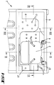
- eine Rückansicht des Kühlmöbels mit eingebautem, zur Rückseite hin offenen Kapselelement und zu rückseitigen freistehendem Kompressormotors;
- Fig. 2
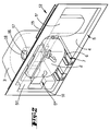
- eine perspektivische Darstellung der Motorraumwandung und des eingesetzten Kapselelements mit darin befindlichem Kompressormotor;
- Fig. 3
- die Motorraumwandung und das Kapselelement in auseinander gezogenem Zustand;
- Fig. 4
- eine Darstellung gemäß Fig. 3, wobei das Kapselelement mit durchlöcherter Wandung ausgebildet ist;
- Fig. 5
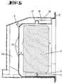
- einen Schnitt durch den Gegenstand gemäß Fig. 1, geschnitten entlang der Linie V-V;
- Fig. 6
- einen Schnitt durch den Gegenstand gemäß Fig. 1, geschnitten entlang der Linie VI-VI`
- Fig. 7
- einen Schnitt durch den Gegenstand gemäß Fig. 1, geschnitten entlang der Linie VII-VII.
- Dargestellt und beschrieben ist zunächst mit Bezug zu Fig. 1 ein - nur teilweise gezeichnetes - Kühlmöbel 1 mit einem Kompressormotor 2 und einem zwischen einer Motorraumwandung 3 (vgl. Fig. 3) und dem Kompressormotor 2 ausgebildeten Kompressormotorraum 4 (vgl. bspw. Fig. 2).
- Der Kompressormotorraum 4 ist unterteilt durch ein Kapselelement 5, das aus geschlossenzelligem Polethylenschaumstoff besteht. Das Kapselelement 5 ist dünnwandig ausgebildet, bspw. mit einer Dicke von 2 mm. Das Kapselelement umgibt gleichsam wie eine Schale den Kompressormotor 2, jedoch mit unterschiedlichem Abstand, wie sich aus den Schnittdarstellungen der Fig. 5 bis 7 im einzelnen ergibt. Auch der Abstand zu der Motorraumwand 3 ist unterschiedlich.
- Wie sich aus Fig. 1, aber auch den Fig. 2 bis 4 insbesondere ergibt, ist das Kapselelement 5 zu einer Rückseite des Kühlmöbels hin offen ausgebildet, zu welcher Rückseite hin auch der Kompressormotor 2 sich freistehend in dem Kapselelement 5 befindet.
- Im einzelnen meist das Kapselelement 5 Stufungen 5', 5'', 5''', 5'''' usw. auf, welche zu einem unterschiedlichen Abstand zu der Motorraumwandung 3 führen. Wie sich zunächst aus der Darstellung gemäß Fig. 5 ergibt, ist ein Abstand a rückseitig des Kompressormotors 2 größer gewählt als ein Abstand b oberseitig des Kompressormotors 2. Der Abstand a entspricht aber etwa dem Abstand c unterseitig des Kompressormotors 2, in bezug auf den lichten Abstand zu einer Motorraumkapsel selbst, ungeachtet der unterhalb des Kompressormotors 2 noch angeordneten Schwingungsdämpfer 6 und der Halterungsschienen 7. Wie sich aus Fig. 6 ergibt, ist der Abstand a rückseitig des Kompressormotors 2 jedoch unterschiedlich gewählt, nämlich im einzelnen derart, daß er in Eckbereichen 8, 9 des Kompressormotors 2 sich bis hin zu einer Anlage an dem Kompressormotor 2 verkleinert. Während einer Seite 10 des Kompressormotors 2, wo insbesondere Kabelanschlüsse und dgl. sich befinden, das Kapselelement 5 sehr nahe - bei 11 - an dem Kompressormotor 2 vorbeigeführt ist, und in etwa rechtwinkliger Ausbildung, ist gegenüberliegend eine in bezug auf die rückwärtige Öffnungsebene E winklige, unter einem Winkel Alpha gegebene Erstreckung des Kapselelemente 5 vorgesehen. Dies führt zu einer geeigneten Absorption nicht nur der unmittelbar von dem Kompressormotor 2 abgestrahlten Schallwellen, sondern auch zu solchen Schallwellen, die an einer - nicht dargestellten - schallharten Wand, gegen welche das Kühlmöbel im Einbauzustand gestellt ist, reflektiert werden. In diesem Zusammenhang von besonderer Bedeutung ist auch noch die seitliche Erstreckung, die insgesamt mit dem Bezugszeichen 12 versehen ist, die über den eigentlichen Kompressormotorraum 4 hinausgeht. Zum einen ist auch in dem Bereich 12 wieder durch geeignete Gestaltung des Kapselelementes 5 ein unterschiedlicher Wandabstand d bzw. e zu der Motorraumwandung 3 geschaffen. Zum anderen ist diese Ausgestaltung dahingehend optimiert, daß eine geeignete Absorption auch in dieser Richtung reflektierter Schallwellen erfolgen kann.
- Wie sich insbesondere aus Fig. 4, aber auch aus den Fig. 1 und 5 bis 7 ergibt, ist das Kapselelement 5 mit Löchern 13 versehen, die einen unmittelbaren Anschluß an Lufträume 14, 15 zwischen dem Kapselelement 5 und der Motorraumwandung 2 ergeben. Im einzelnen ist nicht dargestellt, daß diese Lufträume 14 auch durch geeignete Wulstbildung noch unterteilt sein können, jedoch jeweils mit mehreren Löchern 13 versehen sein können, so daß sich insgesamt ein modifizierter Helmholtz-Resonator ergibt, wie er weiter vorne bereits im einzelnen beschrieben worden ist.
- Bezüglich des Bereiches 12 ist noch von Bedeutung, wie sich insbesondere auch aus dem Querschnitt gemäß Fig. 7 ergibt, daß eine Tiefe t hier wesentlich geringer ist als eine Tiefe t' im Bereich des eigentlichen Kompressormotorraumes 4.
- Wie insbesondere in Fig. 5, aber auch in den Fig. 2 bis 4 zu erkennen ist, ist oberseitig des Kompressormotors 2, integriert in das Kapselelement 5, eine Wasserauffangwanne 16 ausgebildet. Dies lediglich durch einfache Wulstbildung, einen umlaufenden U-Wulst 17, in dem Kapselelement 5. In die Wasserauffangwanne 16 kann bspw. durch eine Öffnung 18 in der Motorraumwandung 3 Kondenswasser oder dgl. von oben hineintropfen. Die Erstreckung der Wasserauffangwanne 16 kann noch wesentlich großer sein als in der Zeichnung dargestellt.
- Die in der vorstehenden Beschreibung, der Zeichnung und den Ansprüchen offenbarten Merkmale der Erfindung können sowohl einzeln als auch in beliebiger Kombination für die Verwirklichung der Erfindung von Bedeutung sein. Alle offenbarten Merkmale sind erfindungswesentlich. In die Offenbarung der Anmeldung wird hiermit auch der Offenbarungsinhalt der zugehörigen/beigefügten Prioritätsunterlagen (Abschrift der Voranmeldung) vollinhaltlich mit einbezogen.
Claims (8)
- Kühlmöbel, insbesondere Kühlschrank (1) mit einem Kompressormotor (2) und einem Kompressormotorraum (4), der eine Motorraumwandung (3) aufweist, gekennzeichnet durch ein dünnwandiges Kapselelement (5) aus geschlossenzelligem Schaumstoff zur Schallabsorption, das entsprechend einer Schale den Kompressormotor (2) umgibt, im wesentlichen jeweils mit Abstand (a, b, c, d) zu dem Kompressormotor (2) und der Motorraumwandung (3), wobei das Kapselelement (5) zu einer Rückseite des Kühlmöbels (1), zu welcher auch der Kompressormotor (2) freiliegt, geöffnet ist.
- Kühlmöbel nach Anspruch 1 oder insbesondere danach, dadurch gekennzeichnet, daß das Kapselelement (5) Stufungen (5', 5'', 5''', 5'''') aufweist, die zu ein unterschiedlichen Abständen zu der Motorraumwandung (3) führen.
- Kühlmöbel nach einem oder mehreren der vorhergehenden Ansprüche oder insbesondere danach, dadurch gekennzeichnet, daß das Kapselelement (5) sich mit vergleichsweise geringer Tiefe (t) seitlich zu dem Kompressormotor (2), jedoch weiterhin zu der Rückseite hin geöffnet, bei integraler Ausführung forterstreckt.
- Kühlmöbel nach einem oder mehreren der vorhergehenden Ansprüche oder insbesondere danach, dadurch gekennzeichnet, daß das Kapselelement (5) gelocht ist.
- Kühlmöbel nach einem oder mehreren der vorhergehenden Ansprüche oder insbesondere danach, dadurch gekennzeichnet, daß das Kühlmöbel domartig ausgebildet ist, derart, daß oberhalb des Kompressormotors (2) ein wesentlicher Abstand zwischen dem Kapselelement (5) und dem Kompressormotor (2) ausgebildet ist, und daß im Bereich des größten Abstandes eine Öffnung (13) in dem Kapselelement ausgebildet ist, zur Schaffung einer gewissen Kaminwirkung.
- Kühlmöbel nach einem oder mehreren der vorhergehenden Ansprüche oder insbesondere danach, dadurch gekennzeichnet, daß integriert in das Kapselelement (5) eine Wasserauffangwanne (16) ausgebildet ist.
- Kühlmöbel nach einem oder mehreren der vorhergehenden Ansprüche oder insbesondere danach, dadurch gekennzeichnet, daß sich die Wasserauffangwanne (16) im wesentlichen oberhalb des Kompressormotors (2) befindet.
- Kühlmöbel nach einem oder mehreren der vorhergehenden Ansprüche oder insbesondere danach, dadurch gekennzeichnet, daß in dem Kapselelement (5) in Zusammenwirkung mit der Motorraumwandung (3) durch Wulstbildung oder dgl. im wesentlichen geschlossene Kammern gebildet sind, welche jeweils mehrfach durch die Öffnungen (13) mit der Umgebung in Verbindung stehen.
Applications Claiming Priority (2)
| Application Number | Priority Date | Filing Date | Title |
|---|---|---|---|
| DE4243320 | 1992-12-21 | ||
| DE4243320A DE4243320A1 (de) | 1992-12-21 | 1992-12-21 | Kühlmöbel |
Publications (3)
| Publication Number | Publication Date |
|---|---|
| EP0603752A2 true EP0603752A2 (de) | 1994-06-29 |
| EP0603752A3 EP0603752A3 (de) | 1994-11-09 |
| EP0603752B1 EP0603752B1 (de) | 1998-02-11 |
Family
ID=6476007
Family Applications (1)
| Application Number | Title | Priority Date | Filing Date |
|---|---|---|---|
| EP93120359A Expired - Lifetime EP0603752B1 (de) | 1992-12-21 | 1993-12-17 | Kühlmöbel |
Country Status (3)
| Country | Link |
|---|---|
| EP (1) | EP0603752B1 (de) |
| AT (1) | ATE163225T1 (de) |
| DE (2) | DE4243320A1 (de) |
Cited By (4)
| Publication number | Priority date | Publication date | Assignee | Title |
|---|---|---|---|---|
| WO2000063627A3 (de) * | 1999-04-15 | 2001-03-15 | Guenther Engineering Gmbh | Kälteanlage für haushaltkühlgeräte |
| WO2004081473A1 (en) * | 2003-03-10 | 2004-09-23 | Electrolux Home Products Corporation N.V. | Noise reduction system |
| KR100750252B1 (ko) | 2006-07-21 | 2007-08-17 | 주식회사 대우일렉트로닉스 | 김치냉장고 기계실의 소음 방지 구조 |
| EP2613054A1 (de) | 2012-01-05 | 2013-07-10 | Emerson Climate Technologies GmbH | Schallschutzabdeckung |
Families Citing this family (5)
| Publication number | Priority date | Publication date | Assignee | Title |
|---|---|---|---|---|
| DE20104425U1 (de) * | 2001-03-14 | 2002-07-25 | Liebherr-Werk Lienz Ges.M.B.H., Lienz | Kühl- und/oder Gefriergerät |
| BRPI0700554A (pt) * | 2007-01-30 | 2008-09-16 | Whirlpool Sa | arranjo de ressonadores para gabinete de aparelho de refrigeração |
| DE102011007423A1 (de) * | 2011-04-14 | 2012-10-18 | BSH Bosch und Siemens Hausgeräte GmbH | Haushaltskältegerät |
| KR101964644B1 (ko) * | 2012-05-10 | 2019-04-02 | 엘지전자 주식회사 | 소음저감부가 구비된 가전기기 |
| EP4293302A4 (de) * | 2021-02-10 | 2025-05-07 | LG Electronics Inc. | Kühlschrank und daran montierte geräuschreduzierungsvorrichtung |
Family Cites Families (10)
| Publication number | Priority date | Publication date | Assignee | Title |
|---|---|---|---|---|
| DE916056C (de) * | 1939-12-07 | 1954-08-02 | Siemens Ag | Mit einer Kaeltemaschine ausgeruesteter Kuehlschrank |
| US2313472A (en) * | 1941-05-07 | 1943-03-09 | Westinghouse Electric & Mfg Co | Refrigeration apparatus |
| DE1006872B (de) * | 1953-06-04 | 1957-04-25 | Licentia Gmbh | Kuehlschrank, insbesondere in Form einer Anrichte bzw. eines Einbaumoebels |
| GB812068A (en) * | 1955-11-30 | 1959-04-15 | Standard Pressed Steel Co | Improvements in or relating to refrigerator cabinets |
| DE2354897C3 (de) * | 1973-11-02 | 1978-07-20 | Danfoss A/S, Nordborg (Daenemark) | Gekapselte Kältemaschine |
| FR2450430A1 (fr) * | 1979-02-27 | 1980-09-26 | Thomson Brandt | Armoire frigorifique a socle moule et procede de fabrication |
| DE3319865C2 (de) * | 1983-06-01 | 1991-01-24 | Licentia Patent-Verwaltungs-Gmbh, 6000 Frankfurt | Kühlgerät mit einer Nische für einen Motorkompressor |
| JPS61218784A (ja) * | 1985-03-25 | 1986-09-29 | Toshiba Corp | 冷凍サイクル装置 |
| DE8909961U1 (de) * | 1989-08-19 | 1990-12-20 | Irbit Research + Consulting Ag, Freiburg/Fribourg | Isolationselement |
| JPH0436567A (ja) * | 1990-06-01 | 1992-02-06 | Hitachi Ltd | 冷蔵庫 |
-
1992
- 1992-12-21 DE DE4243320A patent/DE4243320A1/de not_active Withdrawn
-
1993
- 1993-12-17 AT AT93120359T patent/ATE163225T1/de not_active IP Right Cessation
- 1993-12-17 DE DE59308142T patent/DE59308142D1/de not_active Expired - Fee Related
- 1993-12-17 EP EP93120359A patent/EP0603752B1/de not_active Expired - Lifetime
Cited By (4)
| Publication number | Priority date | Publication date | Assignee | Title |
|---|---|---|---|---|
| WO2000063627A3 (de) * | 1999-04-15 | 2001-03-15 | Guenther Engineering Gmbh | Kälteanlage für haushaltkühlgeräte |
| WO2004081473A1 (en) * | 2003-03-10 | 2004-09-23 | Electrolux Home Products Corporation N.V. | Noise reduction system |
| KR100750252B1 (ko) | 2006-07-21 | 2007-08-17 | 주식회사 대우일렉트로닉스 | 김치냉장고 기계실의 소음 방지 구조 |
| EP2613054A1 (de) | 2012-01-05 | 2013-07-10 | Emerson Climate Technologies GmbH | Schallschutzabdeckung |
Also Published As
| Publication number | Publication date |
|---|---|
| EP0603752B1 (de) | 1998-02-11 |
| DE59308142D1 (de) | 1998-03-19 |
| ATE163225T1 (de) | 1998-02-15 |
| DE4243320A1 (de) | 1994-06-23 |
| EP0603752A3 (de) | 1994-11-09 |
Similar Documents
| Publication | Publication Date | Title |
|---|---|---|
| DE3502000A1 (de) | Dieselaggregat | |
| EP1702187A1 (de) | Einbau-kältegerät | |
| EP0603752B1 (de) | Kühlmöbel | |
| DE2648442A1 (de) | Bett mit schalldaemmung | |
| DE3932243A1 (de) | Schalldaempferanordnung und damit ausgestatteter kuehlschrank | |
| DE2910371C2 (de) | ||
| DE19939482B4 (de) | Anordnung zur Abschirmung von abgasführenden Teilen von Kraftfahrzeugen | |
| EP3710755A1 (de) | Dunstabzugsvorrichtung für ein kochfeld und küchenmöbel mit dunstabzugsvorrichtung | |
| EP2993430B1 (de) | Verkleidung für ein haushaltsgerät sowie haushaltsgerät mit einer verkleidung | |
| DE19957618A1 (de) | Ansaugeinheit einer Klimaanlage für ein Fahrzeug | |
| EP2354652B1 (de) | Gebläsebrenner | |
| DE102011121164A1 (de) | Strahlflächenaufbau mit Absorptionsbox | |
| DE721839C (de) | Vorrichtung zur Daempfung der von Kompressionskaeltemaschinen ausgehenden Geraeusche | |
| EP2326897B1 (de) | Geräuschreduziertes kältegerät | |
| DE102008063391A1 (de) | Kältegerät mit Fachboden | |
| WO2006037745A1 (de) | Kältegerät | |
| DE2804027A1 (de) | Abdeckhaube fuer einen in eine wand eingebauten ventilator | |
| EP2993428A1 (de) | Verkleidung für eine tür eines haushaltsgerätes und tür eines haushaltsgerätes mit einer verkleidung | |
| DE9301542U1 (de) | Lüftergehäuse zur Anordnung in einer Durchlaßöffnung | |
| DE102011002776A1 (de) | Kältegerät und Verfahren zur Herstellung eines Kältegeräts | |
| DE102008011012B4 (de) | Schaltschrank | |
| EP2691711B1 (de) | Kältegerät mit axiallüfter | |
| DE732630C (de) | Vorrichtung zur Geraeuschminderung in Leitungen | |
| EP1070851B1 (de) | Gebläse | |
| CH436759A (de) | Vorrichtung zur Schalldämpfung in von Gas durchströmten Kanälen mittels eines Membranschalldämpfers |
Legal Events
| Date | Code | Title | Description |
|---|---|---|---|
| PUAI | Public reference made under article 153(3) epc to a published international application that has entered the european phase |
Free format text: ORIGINAL CODE: 0009012 |
|
| AK | Designated contracting states |
Kind code of ref document: A2 Designated state(s): AT BE CH DE DK ES FR GB GR IE IT LI LU MC NL PT SE |
|
| PUAL | Search report despatched |
Free format text: ORIGINAL CODE: 0009013 |
|
| AK | Designated contracting states |
Kind code of ref document: A3 Designated state(s): AT BE CH DE DK ES FR GB GR IE IT LI LU MC NL PT SE |
|
| 17P | Request for examination filed |
Effective date: 19941228 |
|
| 17Q | First examination report despatched |
Effective date: 19951114 |
|
| GRAG | Despatch of communication of intention to grant |
Free format text: ORIGINAL CODE: EPIDOS AGRA |
|
| GRAG | Despatch of communication of intention to grant |
Free format text: ORIGINAL CODE: EPIDOS AGRA |
|
| GRAG | Despatch of communication of intention to grant |
Free format text: ORIGINAL CODE: EPIDOS AGRA |
|
| GRAH | Despatch of communication of intention to grant a patent |
Free format text: ORIGINAL CODE: EPIDOS IGRA |
|
| GRAH | Despatch of communication of intention to grant a patent |
Free format text: ORIGINAL CODE: EPIDOS IGRA |
|
| GRAA | (expected) grant |
Free format text: ORIGINAL CODE: 0009210 |
|
| AK | Designated contracting states |
Kind code of ref document: B1 Designated state(s): AT BE CH DE DK ES FR GB GR IE IT LI LU MC NL PT SE |
|
| PG25 | Lapsed in a contracting state [announced via postgrant information from national office to epo] |
Ref country code: NL Free format text: LAPSE BECAUSE OF FAILURE TO SUBMIT A TRANSLATION OF THE DESCRIPTION OR TO PAY THE FEE WITHIN THE PRESCRIBED TIME-LIMIT Effective date: 19980211 Ref country code: IT Free format text: LAPSE BECAUSE OF FAILURE TO SUBMIT A TRANSLATION OF THE DESCRIPTION OR TO PAY THE FEE WITHIN THE PRE;WARNING: LAPSES OF ITALIAN PATENTS WITH EFFECTIVE DATE BEFORE 2007 MAY HAVE OCCURRED AT ANY TIME BEFORE 2007. THE CORRECT EFFECTIVE DATE MAY BE DIFFERENT FROM THE ONE RECORDED.SCRIBED TIME-LIMIT Effective date: 19980211 Ref country code: GR Free format text: LAPSE BECAUSE OF NON-PAYMENT OF DUE FEES Effective date: 19980211 Ref country code: GB Free format text: LAPSE BECAUSE OF FAILURE TO SUBMIT A TRANSLATION OF THE DESCRIPTION OR TO PAY THE FEE WITHIN THE PRESCRIBED TIME-LIMIT Effective date: 19980211 Ref country code: FR Free format text: LAPSE BECAUSE OF FAILURE TO SUBMIT A TRANSLATION OF THE DESCRIPTION OR TO PAY THE FEE WITHIN THE PRESCRIBED TIME-LIMIT Effective date: 19980211 Ref country code: ES Free format text: THE PATENT HAS BEEN ANNULLED BY A DECISION OF A NATIONAL AUTHORITY Effective date: 19980211 |
|
| REF | Corresponds to: |
Ref document number: 163225 Country of ref document: AT Date of ref document: 19980215 Kind code of ref document: T |
|
| REG | Reference to a national code |
Ref country code: CH Ref legal event code: EP |
|
| REF | Corresponds to: |
Ref document number: 59308142 Country of ref document: DE Date of ref document: 19980319 |
|
| PG25 | Lapsed in a contracting state [announced via postgrant information from national office to epo] |
Ref country code: SE Free format text: LAPSE BECAUSE OF FAILURE TO SUBMIT A TRANSLATION OF THE DESCRIPTION OR TO PAY THE FEE WITHIN THE PRESCRIBED TIME-LIMIT Effective date: 19980511 Ref country code: PT Free format text: LAPSE BECAUSE OF FAILURE TO SUBMIT A TRANSLATION OF THE DESCRIPTION OR TO PAY THE FEE WITHIN THE PRESCRIBED TIME-LIMIT Effective date: 19980511 Ref country code: DK Free format text: LAPSE BECAUSE OF FAILURE TO SUBMIT A TRANSLATION OF THE DESCRIPTION OR TO PAY THE FEE WITHIN THE PRESCRIBED TIME-LIMIT Effective date: 19980511 |
|
| NLV1 | Nl: lapsed or annulled due to failure to fulfill the requirements of art. 29p and 29m of the patents act | ||
| REG | Reference to a national code |
Ref country code: IE Ref legal event code: FG4D Free format text: 78855 |
|
| EN | Fr: translation not filed | ||
| REG | Reference to a national code |
Ref country code: CH Ref legal event code: NV Representative=s name: R. A. EGLI & CO. PATENTANWAELTE |
|
| GBV | Gb: ep patent (uk) treated as always having been void in accordance with gb section 77(7)/1977 [no translation filed] |
Effective date: 19980211 |
|
| PG25 | Lapsed in a contracting state [announced via postgrant information from national office to epo] |
Ref country code: IE Free format text: LAPSE BECAUSE OF NON-PAYMENT OF DUE FEES Effective date: 19980924 |
|
| REG | Reference to a national code |
Ref country code: IE Ref legal event code: FD4D Ref document number: 78855 Country of ref document: IE |
|
| PG25 | Lapsed in a contracting state [announced via postgrant information from national office to epo] |
Ref country code: LU Free format text: LAPSE BECAUSE OF NON-PAYMENT OF DUE FEES Effective date: 19981217 |
|
| PLBE | No opposition filed within time limit |
Free format text: ORIGINAL CODE: 0009261 |
|
| STAA | Information on the status of an ep patent application or granted ep patent |
Free format text: STATUS: NO OPPOSITION FILED WITHIN TIME LIMIT |
|
| PG25 | Lapsed in a contracting state [announced via postgrant information from national office to epo] |
Ref country code: BE Free format text: LAPSE BECAUSE OF NON-PAYMENT OF DUE FEES Effective date: 19981231 |
|
| PG25 | Lapsed in a contracting state [announced via postgrant information from national office to epo] |
Ref country code: MC Free format text: THE PATENT HAS BEEN ANNULLED BY A DECISION OF A NATIONAL AUTHORITY Effective date: 19990128 |
|
| 26N | No opposition filed | ||
| BERE | Be: lapsed |
Owner name: ILLBRUCK G.M.B.H. Effective date: 19981231 |
|
| PGFP | Annual fee paid to national office [announced via postgrant information from national office to epo] |
Ref country code: AT Payment date: 19991117 Year of fee payment: 7 |
|
| PGFP | Annual fee paid to national office [announced via postgrant information from national office to epo] |
Ref country code: CH Payment date: 19991118 Year of fee payment: 7 |
|
| PG25 | Lapsed in a contracting state [announced via postgrant information from national office to epo] |
Ref country code: AT Free format text: LAPSE BECAUSE OF NON-PAYMENT OF DUE FEES Effective date: 20001217 |
|
| PG25 | Lapsed in a contracting state [announced via postgrant information from national office to epo] |
Ref country code: LI Free format text: LAPSE BECAUSE OF NON-PAYMENT OF DUE FEES Effective date: 20001231 Ref country code: CH Free format text: LAPSE BECAUSE OF NON-PAYMENT OF DUE FEES Effective date: 20001231 |
|
| REG | Reference to a national code |
Ref country code: CH Ref legal event code: PL |
|
| PGFP | Annual fee paid to national office [announced via postgrant information from national office to epo] |
Ref country code: DE Payment date: 20030204 Year of fee payment: 10 |
|
| PG25 | Lapsed in a contracting state [announced via postgrant information from national office to epo] |
Ref country code: DE Free format text: LAPSE BECAUSE OF NON-PAYMENT OF DUE FEES Effective date: 20040701 |