EP0603891A2 - Connecteur ayant un levier - Google Patents
Connecteur ayant un levier Download PDFInfo
- Publication number
- EP0603891A2 EP0603891A2 EP93120806A EP93120806A EP0603891A2 EP 0603891 A2 EP0603891 A2 EP 0603891A2 EP 93120806 A EP93120806 A EP 93120806A EP 93120806 A EP93120806 A EP 93120806A EP 0603891 A2 EP0603891 A2 EP 0603891A2
- Authority
- EP
- European Patent Office
- Prior art keywords
- lever
- connector housing
- connector
- support shaft
- outer walls
- Prior art date
- Legal status (The legal status is an assumption and is not a legal conclusion. Google has not performed a legal analysis and makes no representation as to the accuracy of the status listed.)
- Granted
Links
- 230000001105 regulatory effect Effects 0.000 claims abstract description 31
- 230000009471 action Effects 0.000 claims description 4
- 230000008901 benefit Effects 0.000 description 4
- 238000010276 construction Methods 0.000 description 4
- 230000004048 modification Effects 0.000 description 3
- 238000012986 modification Methods 0.000 description 3
- 230000007246 mechanism Effects 0.000 description 2
- 238000000034 method Methods 0.000 description 2
- 230000008569 process Effects 0.000 description 2
- 238000003780 insertion Methods 0.000 description 1
- 230000037431 insertion Effects 0.000 description 1
- 238000004519 manufacturing process Methods 0.000 description 1
- 230000005405 multipole Effects 0.000 description 1
Images

Classifications
-
- H—ELECTRICITY
- H01—ELECTRIC ELEMENTS
- H01R—ELECTRICALLY-CONDUCTIVE CONNECTIONS; STRUCTURAL ASSOCIATIONS OF A PLURALITY OF MUTUALLY-INSULATED ELECTRICAL CONNECTING ELEMENTS; COUPLING DEVICES; CURRENT COLLECTORS
- H01R13/00—Details of coupling devices of the kinds covered by groups H01R12/70 or H01R24/00 - H01R33/00
- H01R13/62—Means for facilitating engagement or disengagement of coupling parts or for holding them in engagement
- H01R13/629—Additional means for facilitating engagement or disengagement of coupling parts, e.g. aligning or guiding means, levers, gas pressure electrical locking indicators, manufacturing tolerances
- H01R13/62933—Comprising exclusively pivoting lever
- H01R13/62938—Pivoting lever comprising own camming means
Definitions
- This invention relates to a lever-type connector in which connectors are connected together through leverage, and more particularly, to a lever-type connector with an improved assembling operability.
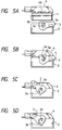
- a connector of this type has an advantage that the connection and disconnection can be effected with a small force, and this concept has been applied particularly to multi-pole connectors. Its basic principle is based on the action of a lever, and a conventional construction disclosed, for example, in Japanese Patent Unexamined Publication No. 4-62772 is broadly shown in Figs. 5(A)-(D).
- a female connector housing 1 in which female terminals are to be accommodated and a male connector housing 2 in which male terminals are to be accommodated are shown.
- the female connector housing 1 can be inserted into the male connector housing 2.
- the male connector housing 2 has a lever 3 having cam grooves 3a mounted so as to be pivotable about support shafts 2a.
- On the female connector housing 1 side are cam follower projections 4a.
- the cam follower projections 4a are arranged on a cover 4 that is to be put on the female connector housing 1.
- the lever 3 is of a two-leg structure and has bearing holes 3b close to the cam grooves 3a, respectively.
- the lever 3 is supported so as to be pivotable relative to the male connector housing 2 by causing the lever support shafts 2a to be engaged with the bearing holes 3b.
- the lever support shafts 2a are formed on and projected from the male connector housing 2.
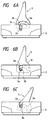
- leg portions 3c of the lever 3 are put on the lever support shafts 2a of the male connector housing 2 as shown in Fig. 6 (A). Then, in this condition, the lever 3 is pushed onto the male connector housing 2 with sufficient force to cause the leg portions 3c to deform elastically so that they open apart from each other to allow the lever 3 to enter.
- the bearing holes 3b formed in the leg portions 3c meet the lever support shafts 2a, respectively, both are engaged with each other, allowing the lever 3 to be pivotally mounted on the male connector housing 2.
- cam grooves 3a must be engaged with the lever support shafts 2a again by taking the cam grooves 3a out of the lever support shafts 2a, which is a cumbersome operation.
- an object of the invention is to provide a lever-type connector that can prevent cam follower projections from entering into bearing holes in a lever and that can be assembled easily and surely to ensure improved assembly.
- a lever-type connector wherein a lever having cam grooves is pivotally mounted between a first connector housing and a second connector housing.
- the second connector housing includes at least one cam follower projection
- the first connector includes a rectangular hood disposed substantially about the said first connector housing, a t least one lever support shaft projecting laterally from the rectangular hood, the lever being mounted on the at least one lever support shaft, outer walls spaced from and outside of lateral walls of the first connector, the lever being mounted between the outer walls and the lateral walls, and structure for preventing the at least one lever support shaft from engaging a respective one of the cam grooves.
- the preventing structure may include at least one regulating projection attached to the lever and a guide groove having a predetermined depth formed in each of the outer walls, the guide groove receiving the at least one regulating projection.
- the regulating projections arranged on the lever enter into the guide grooves formed on the outer walls of the connector housing when the lever is fitted into the connector housing.
- the length of the guide groove is set to cause the regulating projection to abut against the bottom of the guide groove at a stage after the lever support shaft has passed the bearing hole in the lever and before the lever support shaft enters into the cam groove. Therefore, even if the lever is inserted with force, the regulating projections abut against the bottoms of the guide grooves to stop the lever from entering further, which keeps the lever support shafts from entering into the cam grooves.
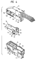
- Fig. 4 shows an overall structure.
- a male connector housing 11 into which male terminals (not shown) are to be inserted is shown in the lower side, whereas a female connector housing 12 into which female terminals are inserted is shown in the upper side.
- a cover 13 On top of the female connector housing 12 is a cover 13, which is designed to entirely cover the upper surface of the female connector housing.
- the cover 13 is engaged with the female connector housing 12 by an engaging mechanism 13a.
- Cam follower projections 17 are formed on and are projected laterally in the middle of lateral walls of the female connector housing 12.
- the cam follower projections 17 are designed to be engaged with cam grooves 16 formed on a lever 14, which will be described later.
- the male connector housing 11 has a rectangular hood 18, whose top surface is open.
- a pair of lever support shafts 19 project laterally from side walls of the hood 18.
- the lever 14, which has been referred to above, is mounted on shafts 19 and is of a two-leg structure.
- the upper ends of the respective leg portions 15, right and left, are connected to each other by a bridge portion 14a.
- Each leg portion 15 has a bearing hole 20 into which the corresponding lever support shaft 19 is inserted.
- the lower end of each leg portion 15 is tapered to form a tapered surface 15a.
- Surfaces 15a are tapered toward the inside of the lever 14.
- Each leg portion 15 has the cam groove 16 engageable with the corresponding cam follower projection 17 that is projected from the cover 13.
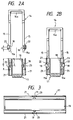
- Concentrical sleeve-like regulating projections 22 project from the peripheries of the bearing holes 20 of the respective leg portions 15 of the lever 14 in such directions that the regulating projections 22 leave the lateral walls of the male connector housing 11 (see Fig. 2).
- On the outer walls 21 are guide grooves 23, each of which is formed so as to extend downward as viewed in Fig. 1 for allowing the corresponding regulating projection 22 to be inserted.
- the length of each guide groove 23 is determined in the following manner.
- the regulating projection 22 is designed to have such a dimensional relationship as to abut against the bottom of the guide groove 23 after the lever support shaft 19 has passed the bearing hole 20 in the lever 14 and before the lever support shaft 19 is engaged with the cam groove 16 when the lever 14 is fitted into the male connector housing 11.
- the assembling operation is performed in the following manner. Holding the male connector housing 11 in one hand and the lever 14 in the other, the leg portions 15 of the lever 14 are inserted into the gaps between the lateral walls and the outer walls 21 of the male connector housing 11 so as to put the regulating projections 22 on the entrances of the guide grooves 23.
- the lever 14 cannot be pushed down any farther. Therefore, even if the lever 14 is pushed down with excessive force, such pushing force is interrupted to hold the lever 14 at that position. As a result, the engagement between the lever support shafts 19 and the cam grooves 16 due to the lever 14 being pushed down by excessive force associated with the connecting operation can be prevented without fail.
- the mounting operation is extremely simple, which provides for improved assembling efficiency.
- the regulating projections 22 are projected so as to be concentric with the bearing holes 22, the regulating projections 22 turn only inside the guide grooves 22 even if the lever 14 is turned. Accordingly, the regulating projections do not hamper the lever 14 from performing its essential function, which is an additional advantage.
- the guide grooves 23 are formed on the outer walls 21 that are arranged to protect the lever 14, no special mechanism is added for the positional regulation of the lever 14. This means that the mold of the male connector housing 11 requires little modification, thus contributing to reduced manufacturing costs.
- the lever-type connector of the present invention it is ensured that the regulating projections will prevent the lever support shafts from entering into the cam grooves. Therefore, the lever support shafts formed on the connector housing are kept from entering into the cam grooves surely, thereby providing an excellent advantage that the lever assembling operation can be performed simply as well as surely.
Landscapes
- Details Of Connecting Devices For Male And Female Coupling (AREA)
Applications Claiming Priority (2)
| Application Number | Priority Date | Filing Date | Title |
|---|---|---|---|
| JP1992093156U JP2583261Y2 (ja) | 1992-12-24 | 1992-12-24 | レバー式コネクタ |
| JP93156/92 | 1992-12-24 |
Publications (3)
| Publication Number | Publication Date |
|---|---|
| EP0603891A2 true EP0603891A2 (fr) | 1994-06-29 |
| EP0603891A3 EP0603891A3 (fr) | 1995-03-08 |
| EP0603891B1 EP0603891B1 (fr) | 1997-03-12 |
Family
ID=14074687
Family Applications (1)
| Application Number | Title | Priority Date | Filing Date |
|---|---|---|---|
| EP93120806A Expired - Lifetime EP0603891B1 (fr) | 1992-12-24 | 1993-12-23 | Connecteur ayant un levier |
Country Status (4)
| Country | Link |
|---|---|
| US (1) | US5445530A (fr) |
| EP (1) | EP0603891B1 (fr) |
| JP (1) | JP2583261Y2 (fr) |
| DE (1) | DE69308786T2 (fr) |
Cited By (1)
| Publication number | Priority date | Publication date | Assignee | Title |
|---|---|---|---|---|
| EP0886345A3 (fr) * | 1993-11-18 | 1999-11-17 | Sumitomo Wiring Systems, Ltd. | Ensemble d'une pluralité de connecteurs à levier |
Families Citing this family (20)
| Publication number | Priority date | Publication date | Assignee | Title |
|---|---|---|---|---|
| EP0606152B1 (fr) * | 1993-01-06 | 2000-03-15 | Sumitomo Wiring Systems, Ltd. | Connecteur à levier de verrouillage |
| US5641296A (en) * | 1994-12-23 | 1997-06-24 | Hjs&E Engineering, Inc. | Folding handle carrier assembly |
| DE19508605C1 (de) * | 1995-03-10 | 1996-07-11 | Harting Elektronik Gmbh | Elektrische Steckverbindung |
| JP3511810B2 (ja) * | 1996-07-25 | 2004-03-29 | 住友電装株式会社 | レバー式コネクタの収容箱におけるレバー仮係止構造 |
| US6039586A (en) * | 1996-09-06 | 2000-03-21 | The Whitaker Corporation | Lever type connector |
| IT1299902B1 (it) * | 1998-03-13 | 2000-04-04 | Marposs Spa | Testa, apparecchiatura e metodo per il controllo di dimensioni lineari di pezzi meccanici. |
| JP3422925B2 (ja) * | 1998-03-30 | 2003-07-07 | 矢崎総業株式会社 | 電気コネクタ |
| US5938458A (en) * | 1998-06-17 | 1999-08-17 | Molex Incorporated | Lever type electrical connector |
| JP3412560B2 (ja) * | 1999-05-18 | 2003-06-03 | 住友電装株式会社 | コネクタ |
| JP3412562B2 (ja) * | 1999-06-14 | 2003-06-03 | 住友電装株式会社 | レバー式コネクタ |
| JP3726638B2 (ja) * | 2000-05-16 | 2005-12-14 | 住友電装株式会社 | レバー式コネクタ |
| JP3726641B2 (ja) | 2000-05-23 | 2005-12-14 | 住友電装株式会社 | レバー式コネクタ |
| JP3961228B2 (ja) * | 2001-03-28 | 2007-08-22 | 矢崎総業株式会社 | レバー嵌合式コネクタ |
| DE10232969B4 (de) * | 2001-07-23 | 2012-08-23 | Sumitomo Wiring Systems, Ltd. | Steckverbinder mit Verriegelungshebel |
| US7052293B2 (en) * | 2004-08-20 | 2006-05-30 | Molex Incorporated | Lever type electrical connector |
| JP5830408B2 (ja) * | 2012-02-20 | 2015-12-09 | 矢崎総業株式会社 | レバー式コネクタ |
| JP5830406B2 (ja) * | 2012-02-20 | 2015-12-09 | 矢崎総業株式会社 | レバー式コネクタ |
| JP6668950B2 (ja) * | 2016-05-30 | 2020-03-18 | 住友電装株式会社 | コネクタ |
| US10135183B1 (en) * | 2017-10-20 | 2018-11-20 | Lear Corporation | Electrical connector with assist lever |
| CN119447903A (zh) * | 2023-08-07 | 2025-02-14 | 贸联国际股份有限公司 | 扣件及连接器 |
Family Cites Families (8)
| Publication number | Priority date | Publication date | Assignee | Title |
|---|---|---|---|---|
| US4586771A (en) * | 1985-03-04 | 1986-05-06 | Amp Incorporated | Connector assembly having camming system for mating and unmating |
| DE3527916A1 (de) * | 1985-08-03 | 1987-02-12 | Cannon Electric Gmbh | Elektrische steckerkupplung |
| US5135410A (en) * | 1990-05-30 | 1992-08-04 | Sumitomo Wiring Systems, Ltd. | Electric connector assembly |
| JP2971531B2 (ja) * | 1990-06-29 | 1999-11-08 | 住友電装株式会社 | コネクタの結合構造 |
| JP2624049B2 (ja) * | 1991-09-13 | 1997-06-25 | 住友電装株式会社 | コネクタ |
| GB2260865B (en) * | 1991-10-21 | 1996-03-27 | Sumitomo Wall Systems Ltd | Lever type connector |
| JP2605201B2 (ja) * | 1992-04-21 | 1997-04-30 | 矢崎総業株式会社 | 低挿入力コネクタ |
| JP3004672U (ja) * | 1994-05-26 | 1994-11-22 | イバ工業株式会社 | 服飾ボタン |
-
1992
- 1992-12-24 JP JP1992093156U patent/JP2583261Y2/ja not_active Expired - Fee Related
-
1993
- 1993-12-22 US US08/172,230 patent/US5445530A/en not_active Expired - Fee Related
- 1993-12-23 DE DE69308786T patent/DE69308786T2/de not_active Expired - Fee Related
- 1993-12-23 EP EP93120806A patent/EP0603891B1/fr not_active Expired - Lifetime
Cited By (1)
| Publication number | Priority date | Publication date | Assignee | Title |
|---|---|---|---|---|
| EP0886345A3 (fr) * | 1993-11-18 | 1999-11-17 | Sumitomo Wiring Systems, Ltd. | Ensemble d'une pluralité de connecteurs à levier |
Also Published As
| Publication number | Publication date |
|---|---|
| JP2583261Y2 (ja) | 1998-10-22 |
| US5445530A (en) | 1995-08-29 |
| DE69308786T2 (de) | 1997-06-19 |
| EP0603891A3 (fr) | 1995-03-08 |
| EP0603891B1 (fr) | 1997-03-12 |
| DE69308786D1 (de) | 1997-04-17 |
| JPH0654253U (ja) | 1994-07-22 |
Similar Documents
| Publication | Publication Date | Title |
|---|---|---|
| US5445530A (en) | Lever-type connector | |
| EP0804821B1 (fr) | Element d'encliquetage de boitier avec dispositif de verification de la position de connecteurs | |
| US5458426A (en) | Double locking connector with fallout preventing protrusion | |
| US5244400A (en) | Electrical connector with fastening cam member | |
| US5183408A (en) | Connector with fitting operation cam members | |
| US5252096A (en) | Connector | |
| US7448888B2 (en) | Connector and a connector assembly | |
| US5464356A (en) | Connector | |
| US5637009A (en) | Connector equipped with engagement detecting member | |
| US6059612A (en) | Block connector | |
| US20020182908A1 (en) | Lever-Type Connector | |
| EP0838882A2 (fr) | Structure de connexion pour circuits imprimés | |
| EP0905823B1 (fr) | Connecteur électrique | |
| JPH04206370A (ja) | 嵌合操作用カム部材付きコネクタ | |
| US5584721A (en) | Connector | |
| US6022238A (en) | Double lock for connector | |
| EP0727846A1 (fr) | Connecteur du type a levier | |
| EP0608114B1 (fr) | Connecteur à levier de verrouillage | |
| EP0994533A1 (fr) | Système de connecteur avec mécanisme de codage | |
| EP0855763B1 (fr) | Connecteur à force d'insertion faible | |
| EP0797274B1 (fr) | Structure de connexion d'un connecteur | |
| US5460534A (en) | Connector using lever action | |
| US5580281A (en) | Connecting structure for screw-down type connector | |
| CA2357739C (fr) | Dispositif de connecteurs males et femelles a emboitement de glissieres males et femelles | |
| US5967857A (en) | Connector assembly |
Legal Events
| Date | Code | Title | Description |
|---|---|---|---|
| PUAI | Public reference made under article 153(3) epc to a published international application that has entered the european phase |
Free format text: ORIGINAL CODE: 0009012 |
|
| AK | Designated contracting states |
Kind code of ref document: A2 Designated state(s): DE FR GB |
|
| PUAL | Search report despatched |
Free format text: ORIGINAL CODE: 0009013 |
|
| AK | Designated contracting states |
Kind code of ref document: A3 Designated state(s): DE FR GB |
|
| 17P | Request for examination filed |
Effective date: 19950504 |
|
| 17Q | First examination report despatched |
Effective date: 19950801 |
|
| GRAG | Despatch of communication of intention to grant |
Free format text: ORIGINAL CODE: EPIDOS AGRA |
|
| GRAH | Despatch of communication of intention to grant a patent |
Free format text: ORIGINAL CODE: EPIDOS IGRA |
|
| GRAH | Despatch of communication of intention to grant a patent |
Free format text: ORIGINAL CODE: EPIDOS IGRA |
|
| GRAA | (expected) grant |
Free format text: ORIGINAL CODE: 0009210 |
|
| AK | Designated contracting states |
Kind code of ref document: B1 Designated state(s): DE FR GB |
|
| REF | Corresponds to: |
Ref document number: 69308786 Country of ref document: DE Date of ref document: 19970417 |
|
| ET | Fr: translation filed | ||
| PLBE | No opposition filed within time limit |
Free format text: ORIGINAL CODE: 0009261 |
|
| STAA | Information on the status of an ep patent application or granted ep patent |
Free format text: STATUS: NO OPPOSITION FILED WITHIN TIME LIMIT |
|
| 26N | No opposition filed | ||
| PGFP | Annual fee paid to national office [announced via postgrant information from national office to epo] |
Ref country code: FR Payment date: 19991208 Year of fee payment: 7 |
|
| PGFP | Annual fee paid to national office [announced via postgrant information from national office to epo] |
Ref country code: GB Payment date: 19991222 Year of fee payment: 7 |
|
| PGFP | Annual fee paid to national office [announced via postgrant information from national office to epo] |
Ref country code: DE Payment date: 19991230 Year of fee payment: 7 |
|
| PG25 | Lapsed in a contracting state [announced via postgrant information from national office to epo] |
Ref country code: GB Free format text: LAPSE BECAUSE OF NON-PAYMENT OF DUE FEES Effective date: 20001223 |
|
| GBPC | Gb: european patent ceased through non-payment of renewal fee |
Effective date: 20001223 |
|
| PG25 | Lapsed in a contracting state [announced via postgrant information from national office to epo] |
Ref country code: FR Free format text: LAPSE BECAUSE OF NON-PAYMENT OF DUE FEES Effective date: 20010831 |
|
| REG | Reference to a national code |
Ref country code: FR Ref legal event code: ST |