EP0603977B1 - Dispositif d'alimentation de flans - Google Patents
Dispositif d'alimentation de flans Download PDFInfo
- Publication number
- EP0603977B1 EP0603977B1 EP93203633A EP93203633A EP0603977B1 EP 0603977 B1 EP0603977 B1 EP 0603977B1 EP 93203633 A EP93203633 A EP 93203633A EP 93203633 A EP93203633 A EP 93203633A EP 0603977 B1 EP0603977 B1 EP 0603977B1
- Authority
- EP
- European Patent Office
- Prior art keywords
- blank
- unfolding
- delivery opening
- blanks
- feeder
- Prior art date
- Legal status (The legal status is an assumption and is not a legal conclusion. Google has not performed a legal analysis and makes no representation as to the accuracy of the status listed.)
- Expired - Lifetime
Links
Images


Classifications
-
- B—PERFORMING OPERATIONS; TRANSPORTING
- B65—CONVEYING; PACKING; STORING; HANDLING THIN OR FILAMENTARY MATERIAL
- B65B—MACHINES, APPARATUS OR DEVICES FOR, OR METHODS OF, PACKAGING ARTICLES OR MATERIALS; UNPACKING
- B65B43/00—Forming, feeding, opening or setting-up containers or receptacles in association with packaging
- B65B43/26—Opening or distending bags; Opening, erecting, or setting-up boxes, cartons, or carton blanks
- B65B43/28—Opening or distending bags; Opening, erecting, or setting-up boxes, cartons, or carton blanks by grippers co-operating with fixed supports
- B65B43/285—Opening or distending bags; Opening, erecting, or setting-up boxes, cartons, or carton blanks by grippers co-operating with fixed supports specially adapted for boxes, cartons or carton blanks
Definitions
- the present invention relates to a device for feeding blanks, for example, for containers to be filled with milk, and more particularly to a blank feeder for use with blanks folded flat so as to be unfoldable to a tubular form of square to rectangular cross section to feed each of the blanks to a bottom forming mandrel as stopped at a feed station by unfolding the blank to the tubular form and fitting the unfolded blank around the mandrel.
- Feeders of the type mentioned above comprise a magazine having a delivery opening at one end and accommodating flat blanks as arranged closely side by side from this end toward the other end thereof, a transport arm for withdrawing the blank from the delivery opening and transporting the blank to a phantom extension of a mandrel, and means for unfolding the blank from the flat form to a tubular form of square cross section while the blank is being transported by the arm, the unfolding means having two unfolding claws provided at edge portions of the delivery opening so as to be engageable respectively with opposite ends of the blank to be withdrawn from the delivery opening.
- the unfolding claws fail to fully unfold the blank and are likely to permit the blank as unfolded once to an expanded state to restore itself to the original flat form during transport.
- An object of the present invention is to provide a blank feeder adapted to reliably unfold blanks from a flat form to a tubular form of square to rectangular cross section.
- the present invention provides a blank feeder for use with blanks which are folded flat so as to be unfoldable to a tubular form of square to rectangular cross section for feeding each of the blanks to a bottom forming mandrel as stopped at a feed station by unfolding the blank to the tubular form and fitting the unfolded blank around the mandrel.
- the blank feeder of the type described above is characterized by at least two unfolding ensuring claws arranged at an intermediate portion of the path of transport of the blank so as to be engageable with the respective blank ends after the blank ends are released from the unfolding claws.
- the unfolding means has the unfolding ensuring claws arranged at an intermediate portion of the path of transport of the blank and engageable with the respective blank ends after the blank ends have been released from the unfolding claws, so that the unfolding ensuring claws unfold the blank to a greater extent even if the blank tends to restore itself to the original flat state during transport. This ensures that the blank will be unfolded from the flat form to the tubular form reliably.
- FIG. 8 shows a blank which has first to fourth side wall panels 11 to 14 continuous with one another endlessly.
- the blank is folded flat so as to be unfoldable to a tubular form of rectangular or square cross section by being folded along a first score 15 between the first side wall panel 11 and the second side wall panel 12 and along a second score 16 between the third side wall panel 13 and the fourth side wall panel 14.
- the first side wall panel 11 has a first engageable portion 17 exntending outward from the corresponding end thereof beyond the adjacent end of the second side wall panel 12, and at the other end of the blank, the fourth side wall panel 14 has a second engageable portion 18 extending outward from the corresponding end thereof beyond the adjacent end of the third side wall panel 13.
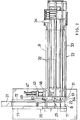
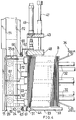
- FIGS. 1 and 2 show a blank feeder, which comprises a magazine 23 disposed at one side of a phantom outward extension of a bottom forming mandrel 21 extending outward and stopped at a feed station, the magazine 23 having a delivery opening 22 at its left end, facing to the left and accommodating flat blanks B as arranged closely side by side from the left end toward the right end of the magazine; transport means 24 for delivering each of the blanks B from the delivery opening 22 and transporting the blank to the outward extension; means 25 for unfolding the blank B from the flat form to the tubular form of square cross section while the blank is being transported by the transport means 24; a holder 25 for holding the tubular blank B on the outward extension; and a loader (not shown) for fitting the blank B held by the holder 26 around the mandrel 21.
- the blanks B are so arranged in a row that the second and third side wall panels 12, 13 of each blank face toward the delivery opening 22 with the panel 12 positioned below the panel 13 (in the state shown in FIG. 8).
- the magazine 23 comprises a vertical rectangular frame 31 defining the delivery opening 22, and a plurality of kinds of guide rails 32, 33 extending rightward from required portions of the frame 31.
- the magazine 23 further has a pressing device 34 for moving the blanks B toward the opening 23 inside the magazine 23.
- the frame 31 comprises an upper frame member 41, lower frame member 42, inner frame member 43 and outer frame member 44.
- the upper frame mbmer 41 is provided with a plurality of retaining pieces 45 for the portion of the second score 16 of the blank B to bear on.
- the lower frame member 42 is provided with a striplike retaining plate 46 for the portion of the blank first score 15 to bear on.
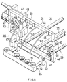
- the inner frame member 43 has a pair of upper and lower horizontal slide rods 47 extending therethrough transversely of the magazine. The rods 47 have outer ends to which a movable frame member 48 is attached.
- a hydraulic cylinder 49 attached to the inner frame member 43 and directed outward has a rod connected to the movable frame member 48.
- the position of the movable frame member 48 is adjusted in accordance with the length of the blanks to be supplied, by the operation of the hydraulic cylinder 49.
- the transport means 24 comprises a suction member 51, a pair of transport arms 52 having the suction member 51 attached to their forward ends and a rotatable shaft 53 having fixed thereto the base ends of the transport arms 52.
- the rotatable shaft 53 extends in parallel to the phantom outward extension of the mandrel 21 and is disposed below the delivery opening 22 so that the second side wall panel 12 of the blank B in the opening 22 can be attracted to the suction member 51.
- the unfolding means 25 comprises a first unfolding claw 61 attached to the outer frame member 44 at a position closer to its lower end than the midportion of the height thereof so as to be engageable with the first engageable portion 17 of the blank B in the the delivery opening 22, a second unfolding claw 62 attached to the movable frame member 48 at a position closer to its upper end than the midportion of the height thereof so as to be engageable with the second engageable portion 18 of the blank B, a first unfolding ensuring claw 64 attached to the outer frame member 44 by a bracket 63 and positioned at the left of the first unfolding claw 61 obliquely therebelow, a second unfolding ensuring claw 66 attached to the movable frame member 48 by a bracket 65 and positioned at the left of the second unfolding claw 62 obliquely therebelow, and a plurality of bent guides 67 each in the form of a circular-arc rod and extending from required portions of the upper frame member 41 toward the holder 26.
- the holder 26 comprises a pair of guide rails 71, 72 extending on opposite sides of and in parallel to the outward extension of the mandrel.
- the guide rails 71, 72 are formed with recesses 73, 74, respectively, as opposed to each other for opposed corners of the tubular blank B to fit in.
- the blank B is unfolded in the manner to be described below with reference to FIG. 7, which shows the second unfolding claw 62 and the second unfolding ensuring claw 66 only.
- the first unfolding claw 61 and the first unfolding ensuring claw 64 although not illustrated in FIG. 7, act substantially in the same manner as the second unfolding claw 62 and the second unfolding ensuring claw 66, the unfolding action of which will be described below.
- the transport arms 52 are raised to an upright position, causing the suction member 51 to attract thereto the second side wall panel 12 of the blank B in the delivery opening 22 (FIG. 7, (a)).
- the arms 52 are slightly inclined from this state, the upper edge portion of the blank B is released from the retaining pieces 45, and at the same time, the second engageable portion 18 is engaged by the unfolding claw 62, whereby the blank B is slightly opened (FIG. 7, (b)).
- the transport arms 52 are further inclined, the lower edge portion of the blank B is released from the retaining plate 46, and approximately at this time, the engageable portion 18 is brought out of engagement with the unfolding claw 62.
- the upper edge portion of the blank B then comes into contact with the bent guides 67, but before the disengagement, the engageable portion 18 is engaged by the unfolding ensuring claw 66, whereby the unfolded blank B is unfolded to a greater extent (FIG. 7, (c)).
- the blank B is now unlikely to restore itself to the original flat form, and subsequently guided to the holder 26 by the bent guides 67 while being unfolded to a tubular form of square cross section.
Landscapes
- Engineering & Computer Science (AREA)
- Mechanical Engineering (AREA)
- Making Paper Articles (AREA)
- Supplying Of Containers To The Packaging Station (AREA)
Claims (4)
- Distributeur de flans destiné à être utilisé avec des flans pliés à plat de façon à pouvoir être déployés sous une forme tubulaire de section transversale carrée à rectangulaire, afin de délivrer chacun des flans à un mandrin de formation de fond, arrêté à un poste de distribution, en déployant le flan sous la forme tubulaire et en ajustant le flan déployé autour du mandrin, le distributeur de flans comprenant:un magasin présentant une ouverture de distribution (22), à une première extrémité, et recevant des flans plats (B), disposés étroitement face contre face depuis ladite première extrémité vers l'autre extrémité du magasin, l'ouverture de distribution étant positionnée de façon à se trouver en vis-à-vis d'un prolongement extérieur imaginaire du mandrin,des moyens de transport (24) destinés à extraire le flan de l'ouverture de distribution et à transporter le flan jusqu'au prolongement extérieur, etdes moyens pour déployer le flan de la forme plate à la forme tubulaire, pendant que le flan est en train d'être transporté par les moyens de transport, les moyens de déploiement comportant au moins deux griffes de déploiement (61, 62) prévues sur des parties de bord de l'ouverture de distribution (22), afin de pouvoir venir respectivement en prise avec des extrémités opposées du flan à extraire de l'ouverture de distribution, caractérisé par au moins deux griffes de maintien de déploiement (64, 66), disposées au niveau d'une partie intermédiaire du trajet de transport du flan, de façon à pouvoir venir en prise avec les extrémités respectives du flan après que les extrémités du flan ont été libérées des griffes de déploiement.
- Distributeur de flans tel que défini dans la revendication 1, dans lequel le magasin comporte un cadre définissant l'ouverture de distribution et comprenant des éléments de cadre supérieur et inférieur, qui s'étendent dans la direction longitudinale des flans reçus dans le magasin, et une paire d'éléments de cadre latéraux reliant chacun entre elles les extrémités des éléments de cadre du même côté, les griffes de déploiement étant montées directement au moins sur les éléments de cadre latéraux respectifs, les griffes de maintien de déploiement étant montées au moins sur les éléments de cadre latéraux respectifs au moyen d'une console de support.
- Distributeur de flans tel que défini dans la revendication 1, dans lequel les moyens de transport comprennent un organe aspirant, des bras de transport ayant l'organe aspirant monté sur leurs extrémités avant, et un arbre rotatif auquel sont fixées les extrémités de base des bras de transport et qui s'étend dans la direction longitudinale des flans reçus dans le magasin.
- Distributeur de flans tel que défini dans la revendication 1, dans lequel un support est prévu pour maintenir le flan tubulaire transporté jusqu'au prolongement extérieur et pour transporter le flan jusqu'au mandrin, et les moyens de déploiement comportent des guides cintrés destinés à guider une partie de bord repliée supérieure du flan, depuis l'ouverture de distribution jusqu'au support, pendant que le flan est en train d'être transporté par les moyens de transport.
Applications Claiming Priority (2)
| Application Number | Priority Date | Filing Date | Title |
|---|---|---|---|
| JP88776/92U | 1992-12-25 | ||
| JP1992088776U JP2584720Y2 (ja) | 1992-12-25 | 1992-12-25 | ブランク供給装置 |
Publications (2)
| Publication Number | Publication Date |
|---|---|
| EP0603977A1 EP0603977A1 (fr) | 1994-06-29 |
| EP0603977B1 true EP0603977B1 (fr) | 1997-04-16 |
Family
ID=13952261
Family Applications (1)
| Application Number | Title | Priority Date | Filing Date |
|---|---|---|---|
| EP93203633A Expired - Lifetime EP0603977B1 (fr) | 1992-12-25 | 1993-12-23 | Dispositif d'alimentation de flans |
Country Status (5)
| Country | Link |
|---|---|
| US (1) | US5484377A (fr) |
| EP (1) | EP0603977B1 (fr) |
| JP (1) | JP2584720Y2 (fr) |
| DE (1) | DE69309873T2 (fr) |
| DK (1) | DK0603977T3 (fr) |
Families Citing this family (10)
| Publication number | Priority date | Publication date | Assignee | Title |
|---|---|---|---|---|
| US5704758A (en) * | 1996-07-26 | 1998-01-06 | Riverwood International Corporation | Article placing assembly and process |
| US6467682B2 (en) * | 2000-03-07 | 2002-10-22 | Zsolt Toth | Carton, a blank for producing a carton, and methods and apparatus for erecting, closing, and sealing a carton |
| CN100425509C (zh) | 2002-05-09 | 2008-10-15 | 富士胶片株式会社 | 包装对象供应设备、箱体供应设备、装箱设备、包装系统及包装方法 |
| US20070194093A1 (en) * | 2006-02-22 | 2007-08-23 | Graphic Packaging International, Inc. | Flat blank carton |
| JP5347680B2 (ja) * | 2009-04-20 | 2013-11-20 | Tdk株式会社 | 開箱装置および箱詰め装置 |
| DE102011054327A1 (de) * | 2011-10-10 | 2013-04-11 | Elopak Systems Ag | Füllmaschine zum Abfüllen von Produkten in Packungsbehälter sowie Verfahren hierzu |
| JP7459737B2 (ja) * | 2020-09-15 | 2024-04-02 | 王子ホールディングス株式会社 | 包装箱の製函方法および製函装置 |
| KR102599074B1 (ko) * | 2021-09-16 | 2023-11-03 | 윤규종 | 단위제품의 포장장치 |
| GB202207633D0 (en) * | 2022-05-25 | 2022-07-06 | Gripple Automation Ltd | Apparatus for simultaneously unloading and erecting a box |
| CN116495282B (zh) * | 2023-06-28 | 2023-11-03 | 康美包(苏州)有限公司 | 包装套筒的供给设备和供给方法 |
Family Cites Families (12)
| Publication number | Priority date | Publication date | Assignee | Title |
|---|---|---|---|---|
| US3220159A (en) * | 1962-10-22 | 1965-11-30 | Celotex Corp | Container erecting and filling apparatus |
| US3249025A (en) * | 1965-01-27 | 1966-05-03 | Ex Cell O Corp | Packaging machine for erecting, filling, and sealing plastic coated paperboard containers |
| JPS4942983U (fr) * | 1972-07-18 | 1974-04-15 | ||
| US3987710A (en) * | 1974-08-09 | 1976-10-26 | Abc Packaging Machine Corporation | Carton squaring mechanism in a case erector |
| US3996843A (en) * | 1974-10-04 | 1976-12-14 | Redington, Incorporated | Method of expanding a carton |
| JPS6126162Y2 (fr) * | 1978-12-27 | 1986-08-06 | ||
| JPH0739634Y2 (ja) * | 1988-12-28 | 1995-09-13 | 四国化工機株式会社 | 容器底部成形用マンドレルへの容器ブランク供給装置 |
| EP0472182B1 (fr) * | 1990-08-22 | 1995-01-18 | Shibuya Kogyo Co., Ltd | Appareil pour ériger des ébauches de boîtes |
| JP2527122Y2 (ja) * | 1990-12-14 | 1997-02-26 | 四国化工機株式会社 | ブランク保持装置 |
| JP2557481Y2 (ja) * | 1990-12-25 | 1997-12-10 | 四国化工機株式会社 | ブランク供給装置 |
| JPH0526806U (ja) * | 1990-12-25 | 1993-04-06 | 四国化工機株式会社 | ブランク供給装置 |
| US5207630A (en) * | 1991-08-13 | 1993-05-04 | Dennis Decker | Case opening apparatus |
-
1992
- 1992-12-25 JP JP1992088776U patent/JP2584720Y2/ja not_active Expired - Fee Related
-
1993
- 1993-12-22 US US08/171,470 patent/US5484377A/en not_active Expired - Fee Related
- 1993-12-23 EP EP93203633A patent/EP0603977B1/fr not_active Expired - Lifetime
- 1993-12-23 DE DE69309873T patent/DE69309873T2/de not_active Expired - Fee Related
- 1993-12-23 DK DK93203633.8T patent/DK0603977T3/da active
Also Published As
| Publication number | Publication date |
|---|---|
| JP2584720Y2 (ja) | 1998-11-05 |
| EP0603977A1 (fr) | 1994-06-29 |
| DE69309873D1 (de) | 1997-05-22 |
| JPH0650841U (ja) | 1994-07-12 |
| DK0603977T3 (da) | 1997-05-26 |
| US5484377A (en) | 1996-01-16 |
| DE69309873T2 (de) | 1997-08-21 |
Similar Documents
| Publication | Publication Date | Title |
|---|---|---|
| EP0182967B1 (fr) | Dispositif pour ériger des boîtes pliées | |
| EP0706476B1 (fr) | Machine d'encartonnage | |
| US5732536A (en) | Tape roll in-series package machine | |
| EP2250093B1 (fr) | Procédé et dispositif pour introduire des sachets (tubulaires) dans des cartons | |
| US4633655A (en) | Case packer | |
| EP0603977B1 (fr) | Dispositif d'alimentation de flans | |
| EP0380905B1 (fr) | Dispositif pour l'alimentation en sacs individuels | |
| US5176608A (en) | Container blank erecter and feeder | |
| EP1656298B1 (fr) | Procede et dispositif d'emballage de tubes | |
| US5127894A (en) | Device for making cartons from flattened tubular blanks | |
| US5180356A (en) | Carton blank erecter and feeder | |
| DE2851202B1 (de) | Verfahren und Vorrichtung zum Verpacken von pulverfoermigen,koernigen oder Stueck-Guetern in einen aus einem Innenbeutel und einem Aussenkarton bestehenden Behaelter | |
| US3621765A (en) | Device for inserting partitions into cartons | |
| US5007889A (en) | Apparatus for feeding container blanks to container bottom forming mandrel | |
| EP0160763B1 (fr) | Appareil et procédé pour présenter des caisses | |
| EP2363344A1 (fr) | Dispositif et procédé destinés à l'emballage d'objets empilables, en particulier de résultats d'impression | |
| GB2232653A (en) | Sleeving machine | |
| JP4573011B2 (ja) | 集積商品の自動箱詰方法及びその装置 | |
| JPH0739630Y2 (ja) | カ−トンの操作装置 | |
| JPH06179424A (ja) | 箱部材の側壁拡開装置 | |
| EP0108947A1 (fr) | Machine d'encartonnage avec dispositif pour redresser et présenter des boîtes pliantes | |
| JPH0615391A (ja) | スタックピンホルダーへのスタックピン引抜・差込装置 | |
| JPS6015522B2 (ja) | トイレットペ−パ−ロ−ルの包装装置 | |
| JPH0118483Y2 (fr) | ||
| JPH0365332A (ja) | サイドフラップ折込み装置 |
Legal Events
| Date | Code | Title | Description |
|---|---|---|---|
| PUAI | Public reference made under article 153(3) epc to a published international application that has entered the european phase |
Free format text: ORIGINAL CODE: 0009012 |
|
| AK | Designated contracting states |
Kind code of ref document: A1 Designated state(s): CH DE DK FR GB LI NL SE |
|
| 17P | Request for examination filed |
Effective date: 19941104 |
|
| GRAG | Despatch of communication of intention to grant |
Free format text: ORIGINAL CODE: EPIDOS AGRA |
|
| 17Q | First examination report despatched |
Effective date: 19960322 |
|
| GRAH | Despatch of communication of intention to grant a patent |
Free format text: ORIGINAL CODE: EPIDOS IGRA |
|
| GRAH | Despatch of communication of intention to grant a patent |
Free format text: ORIGINAL CODE: EPIDOS IGRA |
|
| GRAA | (expected) grant |
Free format text: ORIGINAL CODE: 0009210 |
|
| AK | Designated contracting states |
Kind code of ref document: B1 Designated state(s): CH DE DK FR GB LI NL SE |
|
| REG | Reference to a national code |
Ref country code: CH Ref legal event code: NV Representative=s name: PATENTANWALTSBUERO JEAN HUNZIKER Ref country code: CH Ref legal event code: EP |
|
| REF | Corresponds to: |
Ref document number: 69309873 Country of ref document: DE Date of ref document: 19970522 |
|
| REG | Reference to a national code |
Ref country code: DK Ref legal event code: T3 |
|
| ET | Fr: translation filed | ||
| PLBE | No opposition filed within time limit |
Free format text: ORIGINAL CODE: 0009261 |
|
| 26N | No opposition filed | ||
| PGFP | Annual fee paid to national office [announced via postgrant information from national office to epo] |
Ref country code: GB Payment date: 20011211 Year of fee payment: 9 |
|
| PGFP | Annual fee paid to national office [announced via postgrant information from national office to epo] |
Ref country code: FR Payment date: 20011227 Year of fee payment: 9 |
|
| REG | Reference to a national code |
Ref country code: GB Ref legal event code: IF02 |
|
| PGFP | Annual fee paid to national office [announced via postgrant information from national office to epo] |
Ref country code: CH Payment date: 20020103 Year of fee payment: 9 |
|
| PGFP | Annual fee paid to national office [announced via postgrant information from national office to epo] |
Ref country code: DE Payment date: 20021114 Year of fee payment: 10 |
|
| PGFP | Annual fee paid to national office [announced via postgrant information from national office to epo] |
Ref country code: SE Payment date: 20021216 Year of fee payment: 10 |
|
| PGFP | Annual fee paid to national office [announced via postgrant information from national office to epo] |
Ref country code: DK Payment date: 20021218 Year of fee payment: 10 |
|
| PG25 | Lapsed in a contracting state [announced via postgrant information from national office to epo] |
Ref country code: GB Free format text: LAPSE BECAUSE OF NON-PAYMENT OF DUE FEES Effective date: 20021223 |
|
| PGFP | Annual fee paid to national office [announced via postgrant information from national office to epo] |
Ref country code: NL Payment date: 20021230 Year of fee payment: 10 |
|
| PG25 | Lapsed in a contracting state [announced via postgrant information from national office to epo] |
Ref country code: LI Free format text: LAPSE BECAUSE OF NON-PAYMENT OF DUE FEES Effective date: 20021231 Ref country code: CH Free format text: LAPSE BECAUSE OF NON-PAYMENT OF DUE FEES Effective date: 20021231 |
|
| GBPC | Gb: european patent ceased through non-payment of renewal fee |
Effective date: 20021223 |
|
| REG | Reference to a national code |
Ref country code: CH Ref legal event code: PL |
|
| PG25 | Lapsed in a contracting state [announced via postgrant information from national office to epo] |
Ref country code: FR Free format text: LAPSE BECAUSE OF NON-PAYMENT OF DUE FEES Effective date: 20030901 |
|
| REG | Reference to a national code |
Ref country code: FR Ref legal event code: ST |
|
| PG25 | Lapsed in a contracting state [announced via postgrant information from national office to epo] |
Ref country code: SE Free format text: LAPSE BECAUSE OF NON-PAYMENT OF DUE FEES Effective date: 20031224 |
|
| PG25 | Lapsed in a contracting state [announced via postgrant information from national office to epo] |
Ref country code: DK Free format text: LAPSE BECAUSE OF NON-PAYMENT OF DUE FEES Effective date: 20040102 |
|
| PG25 | Lapsed in a contracting state [announced via postgrant information from national office to epo] |
Ref country code: NL Free format text: LAPSE BECAUSE OF NON-PAYMENT OF DUE FEES Effective date: 20040701 Ref country code: DE Free format text: LAPSE BECAUSE OF NON-PAYMENT OF DUE FEES Effective date: 20040701 |
|
| EUG | Se: european patent has lapsed | ||
| REG | Reference to a national code |
Ref country code: DK Ref legal event code: EBP |
|
| NLV4 | Nl: lapsed or anulled due to non-payment of the annual fee |
Effective date: 20040701 |