EP0604045A2 - Mesures optiques de la réflectométrie temporelle dans un réseau optique multibranches - Google Patents
Mesures optiques de la réflectométrie temporelle dans un réseau optique multibranches Download PDFInfo
- Publication number
- EP0604045A2 EP0604045A2 EP93309699A EP93309699A EP0604045A2 EP 0604045 A2 EP0604045 A2 EP 0604045A2 EP 93309699 A EP93309699 A EP 93309699A EP 93309699 A EP93309699 A EP 93309699A EP 0604045 A2 EP0604045 A2 EP 0604045A2
- Authority
- EP
- European Patent Office
- Prior art keywords
- optical
- subcircuit
- time domain
- wavelengths
- wavelength
- Prior art date
- Legal status (The legal status is an assumption and is not a legal conclusion. Google has not performed a legal analysis and makes no representation as to the accuracy of the status listed.)
- Withdrawn
Links
Images


Classifications
-
- G—PHYSICS
- G01—MEASURING; TESTING
- G01M—TESTING STATIC OR DYNAMIC BALANCE OF MACHINES OR STRUCTURES; TESTING OF STRUCTURES OR APPARATUS, NOT OTHERWISE PROVIDED FOR
- G01M11/00—Testing of optical apparatus; Testing structures by optical methods not otherwise provided for
- G01M11/30—Testing of optical devices, constituted by fibre optics or optical waveguides
- G01M11/31—Testing of optical devices, constituted by fibre optics or optical waveguides with a light emitter and a light receiver being disposed at the same side of a fibre or waveguide end-face, e.g. reflectometers
- G01M11/3109—Reflectometers detecting the back-scattered light in the time-domain, e.g. OTDR
- G01M11/3154—Details of the opto-mechanical connection, e.g. connector or repeater
-
- G—PHYSICS
- G01—MEASURING; TESTING
- G01M—TESTING STATIC OR DYNAMIC BALANCE OF MACHINES OR STRUCTURES; TESTING OF STRUCTURES OR APPARATUS, NOT OTHERWISE PROVIDED FOR
- G01M11/00—Testing of optical apparatus; Testing structures by optical methods not otherwise provided for
- G01M11/30—Testing of optical devices, constituted by fibre optics or optical waveguides
- G01M11/31—Testing of optical devices, constituted by fibre optics or optical waveguides with a light emitter and a light receiver being disposed at the same side of a fibre or waveguide end-face, e.g. reflectometers
- G01M11/3109—Reflectometers detecting the back-scattered light in the time-domain, e.g. OTDR
- G01M11/3136—Reflectometers detecting the back-scattered light in the time-domain, e.g. OTDR for testing of multiple fibers
Definitions
- This invention relates to optical networks and, in particular, to making optical time domain reflectometry measurements.
- Optical time domain reflectometry is a powerful tool for analyzing and characterizing passive optical circuits containing optical fibers, connectors, splicers, etc.
- Optical time domain reflectometry determines the loss and reflection properties of each element in the optical circuit by attaching an instrument to either end of the circuit (replacing either the transmitter or receiver) without disturbing the passive optical circuit.
- Optical time domain reflectometry sends a short pulse of light down an optical circuit and displays the amplitude of the reflected and scattered light as a function of time and distance.
- optical fiber is easily identified by optical time domain reflectometry because of Rayleigh scattering that results from small non-uniformity in the refractive index of glass or other media.
- optical time domain reflectometry instrument (OTDR) 101 of FIG. 1 is incapable of measuring the optical circuit consisting of optical elements 102 through 111. The reason is that when the pulse of light is transmitted through splitter 103, splitter 103 splits the light into two halves. Onehalf the light goes through optical element 104 through 107 and the the other half of the light goes through optical elements 108 through 111. When the two light pulses reflect back from receiver 107 and receiver 111, OTDR 101 cannot distinguish which optical subcircuit is producing which portions of the returning light. Furthermore, if there are unknown numbers of optical splitters, it is not possible to determine how many optical subcircuits exist through use of the prior art optical time domain reflectometry techniques.
- optical circuit having a plurality of optical subcircuits created by optical splitters.
- One or more optical wavelengths are utilized for the transmission of data; whereas, other optical wavelengths are utilized to Perform optical time domain reflectometry measurements.
- each optical path from the optical splitter has inserted into it an optical filter, which allows the transmission of the optical wavelengths utilized for data transmission and one of the optical wavelengths utilized to perform the optical time domain reflectometry measurements.
- An optical time domain reflectometry instrument transmits each of the optical wavelengths utilized for testing individually into the optical circuit and analyses the returned optical pulse. Since only one optical subcircuit allows the passage of any given optical wavelength for testing, each optical subcircuit can be fully analysed.
- FIG. 2 illustrates an optical circuit having two optical subcircuits.
- the first optical subcircuit is formed by optical elements 204 through 208
- the second optical subcircuit is formed by optical elements 209 through 213.
- optical time domain reflectometry instrument 201 uses one optical wavelength to test the first optical subcircuit and a second optical wavelength to test the second optical subcircuit.
- Filter 204 of the first optical subcircuit is responsive to the first test optical wavelength to transmit this optical wavelength in both directions; however, the second test optical wavelength is blocked by filter 204 from being transmitted to the remaining optical components of the first optical subcircuit.
- filter 209 of the second optical subcircuit is responsive to the first test optical wavelength to block that wavelength from being transmitted through the remaining optical elements of the second optical subcircuit but is responsive to the second test optical wavelength to transmit that optical wavelength in both directions.
- optical time domain reflectometry instrument 201 transmits a short light pulse of the first test optical wavelength which is transmitted through the optical elements. The return pulses then are received by optical domain reflectometry instrument 201, which analyses them using well known techniques in the art. Similarly, optical time domain reflectometry instrument 201 uses the second test optical wavelength to test the path comprising elements 202, 203, and 209 through 213.
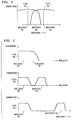
- FIG. 3 illustrates the transmittance of filters 204 and 209 to the first and second optical wavelengths.
- the first test optical wavelength is wavelength 301
- the second test optical wavelength is wavelength 303.
- Wavelength 302 is used during normal operation of the optical circuit, illustrated in FIG. 2, for the transmission of data.
- filter 204 does not transmit light at wavelength 303
- filter 209 transmit light at wavelength 301.
- Techniques for producing filters 204 and 209 are well known in the art.
- FIG. 4 illustrates an optical circuit having three optical subcircuits.
- FIG. 5 illustrates the transmittance characteristic of filters 404, 408, and 412.
- the first optical subcircuit is formed by elements 408 through 411
- the second optical subcircuit is formed by elements 404 through 407
- the third optical subcircuit is formed by elements 412 through 415.
- optical time domain reflectometry instrument 401 utilizes test wavelength 502 as illustrated in FIG. 5.
- optical time domain reflectometry instrument 401 utilizes wavelengths 503 and 504, respectively.
- Wavelength 501 is utilized for the transmission of data through the optical circuit illustrated in FIG. 4.
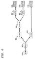
- FIG. 6 illustrates an optical circuit having two optical subcircuits with one of subcircuits having two additional subcircuits.
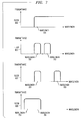
- FIG. 7 illustrates the transmittance characteristic of filters 603, 605, 607, and 609.
- the first optical subcircuit is formed by elements 603 through 608, and the second optical subcircuit is formed by elements 609 and 610.
- the first optical subcircuit has two additional subcircuits.
- the first additional subcircuit is formed by elements 605 and 606, and the second additional subcircuit is formed by elements 607 and 608.
- optical time domain reflectometry instrument 601 utilizes test wavelength 704 as illustrated in FIG. 7.
- optical time domain reflectometry instrument 601 utilizes wavelengths 702 and 703, respectively.
- Wavelength 701 is utilized for the transmission of data through the optical circuit illustrated in FIG. 6.
- Optical filters having the charteristics illustrated in FIGS. 5 and 7 can be produced by a variety of well known optical techniques. Such filters may be purchased from Alliance Technique Industrielle of Evry Cedex, France.
- splitter 203, filter 204, and filter 209 of FIG. 2 can be fabricated as a single component using a fused biconical taper wavelength multiplexer/demultiplexer as described in the article entitled "Passive Fiber Optic Components Made by the Fused Biconical Taper Process", V.J. Tekippe, Proceedings of the Fifth National Symposium on Optical Fibers and Their Applications, Warsaw, Poland, February 21-23, 1989, SPIE Vol. 1085, 1990.
Landscapes
- Physics & Mathematics (AREA)
- Optics & Photonics (AREA)
- Chemical & Material Sciences (AREA)
- Analytical Chemistry (AREA)
- General Physics & Mathematics (AREA)
- Optical Couplings Of Light Guides (AREA)
- Testing Of Optical Devices Or Fibers (AREA)
- Optical Communication System (AREA)
Applications Claiming Priority (2)
| Application Number | Priority Date | Filing Date | Title |
|---|---|---|---|
| US07/995,103 US5383015A (en) | 1992-12-22 | 1992-12-22 | Optical time domain reflectometry measurements on a multi-branch optical network using multiwavelength pass filters |
| US995103 | 1992-12-22 |
Publications (2)
| Publication Number | Publication Date |
|---|---|
| EP0604045A2 true EP0604045A2 (fr) | 1994-06-29 |
| EP0604045A3 EP0604045A3 (fr) | 1995-06-07 |
Family
ID=25541393
Family Applications (1)
| Application Number | Title | Priority Date | Filing Date |
|---|---|---|---|
| EP93309699A Withdrawn EP0604045A3 (fr) | 1992-12-22 | 1993-12-03 | Mesures optiques de la réflectométrie temporelle dans un réseau optique multibranches. |
Country Status (4)
| Country | Link |
|---|---|
| US (1) | US5383015A (fr) |
| EP (1) | EP0604045A3 (fr) |
| JP (1) | JPH06229869A (fr) |
| CA (1) | CA2107454A1 (fr) |
Cited By (2)
| Publication number | Priority date | Publication date | Assignee | Title |
|---|---|---|---|---|
| EP0784388A3 (fr) * | 1996-01-12 | 2001-05-02 | Kokusai Denshin Denwa Kabushiki Kaisha | Système de surveillance de ligne de communication optique |
| CN102445326A (zh) * | 2011-09-20 | 2012-05-09 | 电子科技大学 | 基于时域的光谱探测系统 |
Families Citing this family (19)
| Publication number | Priority date | Publication date | Assignee | Title |
|---|---|---|---|---|
| GB9202564D0 (en) * | 1992-02-07 | 1992-03-25 | Marconi Gec Ltd | Optical signal transmission network |
| US5664033A (en) * | 1994-04-05 | 1997-09-02 | Tektronix, Inc. | Remote fiber test system using a non-blocking N×N mechanical fiber optical switch |
| US5649036A (en) * | 1994-04-05 | 1997-07-15 | Tektronix, Inc. | Remote fiber test system using mechanical optical switches |
| US5539560A (en) * | 1994-12-05 | 1996-07-23 | Photon Kinetics, Inc. | Optical router with optical control |
| US5557400A (en) * | 1995-02-15 | 1996-09-17 | Hewlett-Packard Company | Multiplexed sensing using optical coherence reflectrometry |
| US5936719A (en) * | 1996-07-16 | 1999-08-10 | Johnson; Robert W. | Test unit and method for simultaneous testing of multiple optical fibers |
| JP3439323B2 (ja) * | 1997-06-18 | 2003-08-25 | 安藤電気株式会社 | 多段多分岐光線路の試験装置 |
| AU9675898A (en) | 1997-09-29 | 1999-04-23 | Tollgrade Communications, Inc. | Frequency agile transponder |
| US5859695A (en) * | 1997-12-23 | 1999-01-12 | Honeywell Inc. | Method of and system for characterization of fiber optic connections in situ |
| CA2321915C (fr) * | 1998-02-23 | 2007-04-17 | Sumitomo Electric Industries, Ltd. | Systeme et procede pour le controle de ligne de derivation |
| JP3527844B2 (ja) * | 1998-03-11 | 2004-05-17 | 安藤電気株式会社 | 多分岐光線路試験方法および装置 |
| US6526189B1 (en) | 2001-06-13 | 2003-02-25 | The United States Of America As Represented By The Secretary Of The Army | Scour sensor assembly |
| US8893174B2 (en) | 2002-12-16 | 2014-11-18 | Centurylink Intellectual Property Llc | Method and system for providing customized media content |
| US7187861B2 (en) | 2003-10-15 | 2007-03-06 | Exfo Electro-Optical Engineering Inc. | Method and apparatus for testing optical networks |
| KR100687710B1 (ko) * | 2004-11-20 | 2007-02-27 | 한국전자통신연구원 | 수동형 광가입자망 시스템에서의 광선로 감시 방법 및 장치 |
| US10270554B2 (en) | 2015-09-22 | 2019-04-23 | Exfo Inc. | Optical power measurement in a passive optical network |
| US9831948B2 (en) | 2015-09-22 | 2017-11-28 | Exfo Inc. | Optical power measurement in a passive optical network |
| US10498460B2 (en) * | 2018-03-02 | 2019-12-03 | Juniper Networks, Inc. | Amplified multistage demultiplexer |
| CN114430512B (zh) * | 2020-10-29 | 2023-04-28 | 华为技术有限公司 | 端口识别的方法和装置 |
Family Cites Families (10)
| Publication number | Priority date | Publication date | Assignee | Title |
|---|---|---|---|---|
| FR2597986B1 (fr) * | 1986-04-28 | 1990-09-21 | Foucault Marc | Dispositif a coupleur optique, pour calibrer ou etalonner un reflectometre, systeme d'echometrie et procedes de caracterisation d'un coupleur et de mesure d'attenuations utilisant ce dispositif |
| GB8727846D0 (en) * | 1987-11-27 | 1987-12-31 | British Telecomm | Optical communications network |
| JP2721211B2 (ja) * | 1988-11-24 | 1998-03-04 | 古河電気工業株式会社 | 分岐光線路の損失分布測定装置 |
| JP2737788B2 (ja) * | 1988-12-05 | 1998-04-08 | 古河電気工業株式会社 | 光スイッチを含む光線路の損失分布測定装置 |
| GB8828408D0 (en) * | 1988-12-06 | 1989-01-05 | British Telecomm | Loss detector |
| US5128619A (en) * | 1989-04-03 | 1992-07-07 | Bjork Roger A | System and method of determining cable characteristics |
| CA2031870C (fr) * | 1989-12-11 | 1995-08-08 | Nobuo Tomita | Dispositif et methode de detection des defauts dans les systemes de transmission optiques |
| DE69116014T2 (de) * | 1990-07-06 | 1996-05-15 | Nippon Electric Co | Optischer Wellenleiterschalter für zwei Wellenlängen |
| EP0625295B1 (fr) * | 1992-02-07 | 2000-04-05 | Marconi Communications Limited | Reseau de transmission de signaux optiques |
| GB9202564D0 (en) * | 1992-02-07 | 1992-03-25 | Marconi Gec Ltd | Optical signal transmission network |
-
1992
- 1992-12-22 US US07/995,103 patent/US5383015A/en not_active Expired - Lifetime
-
1993
- 1993-09-30 CA CA002107454A patent/CA2107454A1/fr not_active Abandoned
- 1993-12-03 EP EP93309699A patent/EP0604045A3/fr not_active Withdrawn
- 1993-12-22 JP JP5345561A patent/JPH06229869A/ja active Pending
Cited By (2)
| Publication number | Priority date | Publication date | Assignee | Title |
|---|---|---|---|---|
| EP0784388A3 (fr) * | 1996-01-12 | 2001-05-02 | Kokusai Denshin Denwa Kabushiki Kaisha | Système de surveillance de ligne de communication optique |
| CN102445326A (zh) * | 2011-09-20 | 2012-05-09 | 电子科技大学 | 基于时域的光谱探测系统 |
Also Published As
| Publication number | Publication date |
|---|---|
| EP0604045A3 (fr) | 1995-06-07 |
| US5383015A (en) | 1995-01-17 |
| JPH06229869A (ja) | 1994-08-19 |
| CA2107454A1 (fr) | 1994-06-23 |
Similar Documents
| Publication | Publication Date | Title |
|---|---|---|
| US5383015A (en) | Optical time domain reflectometry measurements on a multi-branch optical network using multiwavelength pass filters | |
| US10432302B1 (en) | Bidirectional optical fiber auto-notifier test system | |
| US9709460B2 (en) | Method and system for measuring an optical loss value of an optical fiber link | |
| US5754284A (en) | Optical time domain reflectometer with internal reference reflector | |
| US7469101B1 (en) | Optoelectronic marker for determining ownership of fiber optic cable | |
| EP1558905B1 (fr) | Procede d'evaluation de fibres par pmd au moyen d'une reflectometrie optique temporelle a polarisation | |
| DE3831797C1 (de) | Funktionstestsystem für Lichtwellenleiter, insbesondere in mittels Laser auslösbaren Waffensystemen | |
| KR910013775A (ko) | 광전송로의 고장위치를 판별하는 방법 및 이 방법에 사용하는 광필터형 판별기 | |
| US7310134B2 (en) | Device and method of optical fiber condition monitoring in optical networks | |
| EP3346250A1 (fr) | Procédé et système permettant de différencier les pertes de macrocourbure des pertes d'épissure et de connecteur dans des liaisons à fibre optique | |
| CN101292145A (zh) | 利用potdr轨迹来评估光纤pmd的方法 | |
| WO2000003504A1 (fr) | Procede et dispositif pour effectuer des mesures de controle et de surveillance sur des lignes de transmission optique | |
| EP0622912B1 (fr) | Réseau de transmission de signaux optiques | |
| US5008545A (en) | High resolution optical fault locator | |
| US20070091297A1 (en) | Optical time domain reflectometry system at different wavelengths | |
| EP3528401A1 (fr) | Mesure otdr unique pour une pluralité de fibres | |
| CA2008799A1 (fr) | Methode de reflexion de la lumiere pour mesurer l'affaiblissement de transmission dans les guides de lumiere a fibre optique | |
| CN101228427B (zh) | 使用复合potdr踪迹来评估光纤pmd的方法 | |
| JP2002139403A (ja) | 分岐光線路の試験方法 | |
| CN114189280B (zh) | 一种光时域反射仪多波长可带光测试的方法 | |
| Iida et al. | Fresnel reflection analysis for optical fibre identification employing with three-wavelength OTDR | |
| US7317518B2 (en) | Determination of an optical property of a DUT by OTDR measurement | |
| CN210183335U (zh) | 一种单轴光纤干涉仪及消除光纤振动盲区的定位装置 | |
| CN219514082U (zh) | 多波长可带光测试的光时域反射仪 | |
| Mai et al. | Fiber optic test equipment-evaluation of OTDR dead zones and ORLM return loss |
Legal Events
| Date | Code | Title | Description |
|---|---|---|---|
| PUAI | Public reference made under article 153(3) epc to a published international application that has entered the european phase |
Free format text: ORIGINAL CODE: 0009012 |
|
| AK | Designated contracting states |
Kind code of ref document: A2 Designated state(s): DE ES FR GB IT |
|
| PUAL | Search report despatched |
Free format text: ORIGINAL CODE: 0009013 |
|
| AK | Designated contracting states |
Kind code of ref document: A3 Designated state(s): DE ES FR GB IT |
|
| 17P | Request for examination filed |
Effective date: 19951123 |
|
| 17Q | First examination report despatched |
Effective date: 19960905 |
|
| STAA | Information on the status of an ep patent application or granted ep patent |
Free format text: STATUS: THE APPLICATION IS DEEMED TO BE WITHDRAWN |
|
| 18D | Application deemed to be withdrawn |
Effective date: 19970318 |