EP0604077B1 - Ausgangsabtastsystem mit mehrstrahligen Laserdioden - Google Patents
Ausgangsabtastsystem mit mehrstrahligen Laserdioden Download PDFInfo
- Publication number
- EP0604077B1 EP0604077B1 EP93309969A EP93309969A EP0604077B1 EP 0604077 B1 EP0604077 B1 EP 0604077B1 EP 93309969 A EP93309969 A EP 93309969A EP 93309969 A EP93309969 A EP 93309969A EP 0604077 B1 EP0604077 B1 EP 0604077B1
- Authority
- EP
- European Patent Office
- Prior art keywords
- beams
- laser
- group
- laser beams
- derived
- Prior art date
- Legal status (The legal status is an assumption and is not a legal conclusion. Google has not performed a legal analysis and makes no representation as to the accuracy of the status listed.)
- Expired - Lifetime
Links
- 230000003287 optical effect Effects 0.000 claims description 114
- 108091008695 photoreceptors Proteins 0.000 claims description 36
- 230000010287 polarization Effects 0.000 claims description 18
- 238000000034 method Methods 0.000 claims description 8
- 238000010408 sweeping Methods 0.000 claims description 8
- 238000001914 filtration Methods 0.000 claims 6
- 230000005540 biological transmission Effects 0.000 description 11
- 230000009977 dual effect Effects 0.000 description 6
- 239000003086 colorant Substances 0.000 description 5
- 238000003491 array Methods 0.000 description 4
- 238000010521 absorption reaction Methods 0.000 description 2
- 239000000463 material Substances 0.000 description 2
- 238000004140 cleaning Methods 0.000 description 1
- 239000002131 composite material Substances 0.000 description 1
- 238000010276 construction Methods 0.000 description 1
- 230000003111 delayed effect Effects 0.000 description 1
- 230000000694 effects Effects 0.000 description 1
- 238000003384 imaging method Methods 0.000 description 1
- 239000000203 mixture Substances 0.000 description 1
- 239000002985 plastic film Substances 0.000 description 1
- 239000000758 substrate Substances 0.000 description 1
Images



Classifications
-
- H—ELECTRICITY
- H04—ELECTRIC COMMUNICATION TECHNIQUE
- H04N—PICTORIAL COMMUNICATION, e.g. TELEVISION
- H04N1/00—Scanning, transmission or reproduction of documents or the like, e.g. facsimile transmission; Details thereof
- H04N1/46—Colour picture communication systems
- H04N1/50—Picture reproducers
- H04N1/506—Reproducing the colour component signals picture-sequentially, e.g. with reproducing heads spaced apart from one another in the subscanning direction
-
- G—PHYSICS
- G02—OPTICS
- G02B—OPTICAL ELEMENTS, SYSTEMS OR APPARATUS
- G02B26/00—Optical devices or arrangements for the control of light using movable or deformable optical elements
- G02B26/08—Optical devices or arrangements for the control of light using movable or deformable optical elements for controlling the direction of light
- G02B26/10—Scanning systems
- G02B26/12—Scanning systems using multifaceted mirrors
- G02B26/123—Multibeam scanners, e.g. using multiple light sources or beam splitters
Definitions
- the present invention relates to multiple beam output scanning systems.
- a latent image is formed on a charged photoreceptor, usually by raster sweeping a modulated laser beam across the photoreceptor.
- the latent image is then used to create a permanent image by transferring and fusing toner that was electrostatically attracted to the latent image onto a recording medium.
- ROSs Raster Output Scanners
- the beam sweep speed problem becomes very important when printing in color at high speed. This is because a color xerographic printer overlaps separate images for each color, called a system color, that is printed. While a dual color printer uses only two images, a full color printer typically requires four images: one for each of the three primary colors of cyan, magenta, yellow, and an additional image for black.
- Multipass printers by sequentially transferring and fusing overlapped system colors onto a single recording medium that is passed multiple times, once for each system color, through the printer.
- Multistation and single station/multiposition printers have greater printed page output than multipass printers operating at the same raster sweep speed.
- the commercial introduction of multistation and single station/multiposition printers has been delayed by 1) cost problems, at least partially related to the cost of multiple xerographic stations, each of which has its own ROS, and 2) image quality problems, at least partially related to the difficulty of producing separate images on each photoreceptor and then registering (overlapping) the separate images to produce a color output.
- Proposed prior art multistation printers e.g. US-A-4,847,642 usually use an individual ROS (each comprised of a separate polygon mirror, lens systems, and related optical components) for each station. Problems with such systems include the high cost of producing nearly identical multiple ROSs and the difficulty of registering the system colors.
- US-A-5,068,677 discloses a laser beam scanning apparatus including plural laser beam sources for emitting laser beams modulated by a picture signal and having different characteristics from each other, a beam composition device for composing the beams emitted from the sources to form one laser beam, a deflecting device for deflecting the composite beam in a main scanning direction, and a beam splitter for splitting the deflected beam on the basis of the characteristic thereof.
- the apparatus further includes a beam selecting device for selecting the beam in correspondence with the characteristic of the beam split by the splitter so as to transmit the beam with a specified characteristic and reflect the beam with a characteristic different from that of the transmitted beam.
- the invention provides a raster output scanning apparatus, comprising: means for producing a bundle of coaxially overlapping first, second, third, and fourth laser beams that originate from a substantially common spatial location, wherein said first and second laser beams have different wavelengths but similar first polarizations, wherein said third and fourth laser beams have differing wavelengths but similar second polarizations which are substantially orthogonal to said first polarizations, wherein said first and third laser beams have substantially the same wavelength, and wherein said second and fourth laser beams have substantially the same wavelength; means for sweeping said bundle; a first beamsplitter for receiving said swept bundle and for splitting said bundle into first and second groups of beams that are derived from said first, second, third, and fourth laser beams; a first beam separator receiving said first group of beams, said first beam separator for absorbing said first group's beams that are derived from said third and fourth laser beams and for directing said first group's beams that are derived from said first and second laser beams onto a
- a bundle of orthogonally polarized and dissimilar wavelength coaxial laser beams is split into multiple groups of beams by an optical beam splitter.
- Each group of beams then passes through individual polarizers which transmit similarly polarized laser beams while absorbing the orthogonally polarized beams.
- Those transmitted beams are then split by an optical beam splitter into one or more sets of identically polarized, but dissimilar wavelength, beams which pass through one or more optical filters.
- Each optical filter transmits one beam at a specified wavelength while absorbing the others.
- the bundle of laser beams is separated into individual beams.
- the invention further provides ROS according to claim 7 of the appended claims.
- This embodiment first splits the bundle of coaxial laser beams into a plurality of bundles by using one or more optical beam splitters. Each bundle of laser beams is then passed through a combination comprised of a polarizer and an optical filter. Each polarizer/filter combination transmits one component beam of the bundle, corresponding to a unique combination of polarization and wavelength, while absorbing the others. In this way, separate and isolated beams are obtained.
- the described embodiments beneficially include devices, such as mirrors, to set each laser beam's optical path length the same.
- the apparatus further includes a second beam separator for receiving said fourth group of beams, said second beam separator for absorbing said fourth group's beam that are derived from said first laser beam and for directing said fourth group's beam that is derived from said third beam onto a third optical path.
- a second beam separator for receiving said fourth group of beams, said second beam separator for absorbing said fourth group's beam that are derived from said first laser beam and for directing said fourth group's beam that is derived from said third beam onto a third optical path.
- the apparatus may further include a second optical filter receiving said second group of beams, said second optical filter for absorbing said second group's beams that are derived from said first and third laser beams and for directing said second group's beams that are derived from said second and fourth laser beams onto a fourth optical path; a third beam splitter receiving said beams on said fourth optical path, said third beam splitter for splitting its received beams into fifth and sixth groups of beams that are derived from said second and fourth laser beams; a third beam separator for receiving said fifth group of beams, said third beam separator for absorbing said fifth group's beam that is derived from said fourth laser beam and for directing said fifth group's beam that is derived from said second beam onto a fifth optical path, and a fourth beam separator for receiving said sixth group of beams, said fourth beam separator for absorbing said sixth group's beam that is derived from said second laser beam and for directing said sixth group's beam that are derived from said fourth beam onto a sixth optical path.
- the apparatus may further include one or more photoreceptors; and means for directing said laser beams on said second, third, fifth and sixth optical paths onto (1) first, second, third, and fourth photoreceptors, respectively, or (2) onto a single photoreceptor.
- the directing means includes means, preferably including a mirror, for equalizing the optical path lengths of at least two of said laser beams on said second, third, fifth and sixth optical paths from said first beam splitter to the, or their respective, photoreceptor(s).
- the invention further provides a method of separating individual laser beams according to claims 8 and 9 of the appended claims.
- absorptive polarizers and optical filters improves on the prior art teachings by reducing the cost and complexity of the scanning apparatus while improving optical performance.
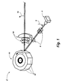
- a basic raster output scanner 2 used in the illustrated embodiments of the present invention is described with reference to FIG. 1.
- the raster output scanner 2 includes a laser source 4 that outputs multiple laser beams 6 from a substantially common spatial location.
- FIG. 1 shows four beams 6. For clarity, only the chief rays of the beams are shown.
- Each beam may be independently modulated with data appropriate to expose a photoreceptive element with a desired image.
- An input optical system 8 directs the laser beams 6 onto overlapping, coaxial optical paths such that they illuminate common areas of a rotating polygon mirror 10 having a plurality of facets 12.
- the polygon mirror 10 repeatedly and simultaneously deflects the laser beams in the direction indicated by the arrow 16.
- the deflected laser beams are input to a set of imaging and correction optics 18 that focuses the laser beams and corrects for errors such as polygon angle error and wobble.
- the raster output scanner 2 (not all components of which are shown in FIG. 2) is used in a dual beam apparatus 50 illustrated in FIG. 2.
- the raster output scanner 2 outputs only two laser beams (instead of four as shown in FIG. 1) that are designated 54 and 56. Again, as in FIG. 1, only the chief rays are shown.
- the beams have substantially the same optical wavelength, but are linearly polarized in orthogonal directions in the plane perpendicular to their propagation direction.
- the laser beams 54 and 56 are, respectively, divided into beams 58 and 60 and into beams 62 and 64 by a beam splitter 70.
- the laser beams 58 and 60 have substantially equal intensities, as do the laser beams 62 and 64.
- the beam splitter 70 is a partially transparent metallic film or multiple layer dielectric film constructed such that half of the intensity of an incident optical beam is transmitted while the other half is reflected. Such beam splitters are well known to those skilled in the applicable arts and are frequently used optical components.
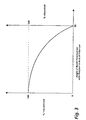
- the laser beams 58 and 62 pass to a polarizer 74 that has transmission characteristics as shown in FIG. 3.
- the optical polarizer 74 is made from a material which absorbs light polarized in a particular direction while transmitting light polarized in the orthogonal direction.
- the polarizer 74 is aligned such that it absorbs beam 62 and transmits beam 58.
- beams 60 and 64 reflect off a mirror 76 and pass through an absorptive polarizer 78.
- Polarizer 78 which has the same transmission characteristics as the polarizer 74, is aligned such that it absorbs beam 60 and transmits beam 64.
- a mirror 80 reflects the laser beam 64 onto a photoreceptor 82, while a mirror 86 reflects the laser beam 58 onto a photoreceptor 90.
- the apparatus 50 is useful for two color printing since the image created on each photoreceptor corresponds to a different system color.
- the optical components 70, 76, 80, and 86 are positioned and oriented such that the optical path lengths from the laser source 4 (not shown in FIG. 2) to the photoreceptors 82 and 90 are substantially equal.
- the dual laser beam apparatus of FIG. 2 uses a laser device 4 that generates coaxially overlapping, cross-polarized laser beams.
- the laser device 4 may be either a monolithic diode laser array, or it may be two non-monolithic diode lasers closely spaced in a single integrated package. Orthogonality of the linearly polarized beams may be established either by the relative orientation of the two laser chips within the package, or by the relative orientation of the linearly polarized beams emitted by a monolithic laser array, as disclosed in US-As 5,412,678 and 5,396,508. With either type of source, the laser device 4 provides a substantially common spatial origin for both laser beams.
- the polarizers 74 and 78 have optical transmission/reflection characteristics as shown in FIG. 3.
- Polarizers of the absorption-type commonly known asdichroic polarizers, are well known to those in the applicable arts. Reference may be made to E.H. Land, Journ. of the Optical Society of America, vol. 41, beginning on pp. 957 (1951). Polarizers of this type are often made by embedding a dichroic polarizing material in a plastic sheet. Their polarization properties are relatively insensitive to changes in the wavelength and angle of the incident light. Consequently they enable improved optical performance at reduced cost when used in a multiple beam scanning apparatus as disclosed in the present invention.
- the apparatus illustrated in FIG. 2 readily produces similarly dimensioned beams at the beamsplitter 70.
- the problem of maintaining equal optical path lengths for each beam reduces to the much simpler problem of maintaining substantially equal optical path lengths from thesplitter 70 to the photoreceptors 82 and 90.
- Equal optical path lengths are set by properly positioning mirrors 76, 80, and 86. Further, registration problems are reduced since the characteristics of the mirror surface area and the related optics which sweep and form both beams are common to both. Furthermore, since both beams are nominally at the same wavelength, the beam forming optics do not have to be designed to simultaneously focus multiple wavelengths at the same distance.
- a two color xerographic print may be produced. Although details of the structure and operation of such means are beyond the scope of the present disclosure, they are well known to those skilled in the art.
- FIG. 4 shows another dual beam apparatus 100.
- Apparatus 100 is a single station/multiposition printer that using the raster output scanner 2 (including polygon 10 and optics 18), simultaneously deflects the two laser beams 54 and 56 across spatially separated regions of one moving photoreceptor 108.
- each laser beam has nominally the same optical wavelength but is orthogonally polarized with respect to the other laser beam.
- the laser beams 54 and 56 are divided into beams 58 and 60, and into beams 62 and 64 by the beam splitter 70. Again, the laser beams 58 and 60, and 62 and 64 have substantially equal intensities.
- the laser beams 58 and 62 pass to the polarizer 74, again aligned such that it absorbs beam 62 while transmitting beam 58.
- the beams 60 and 64 reflect off the mirror 76 and pass to the polarizer 78, again aligned such that it absorbs beam 60 and transmits beam 64.
- mirrors 162 and 164 direct the laser beam 58 onto an area of the photoreceptor 108.
- Mirrors 168 and 170 direct laser beam 64 onto a separate area of the photoreceptor 108.
- a two color xerographic print may be produced.
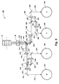
- FIG. 5 shows a simplified, schematic view of an embodiment apparatus 200 in which four laser beams, designated laser beams 212, 214, 216, and 218, are simultaneously scanned across four moving photoreceptors. Once again, only the chief rays are shown.
- the apparatus 200 is a multiple station printer which uses the raster output scanner 2 of FIG. 1 (including polygon 10, and optics 18, and laser device 4) to produce the four laser beams (not all components of the raster output scanner 2 are shown in FIG. 5).
- Two of the beams, i.e. laser beams 214 and 216 have the same wavelength, about 680 nanometers.
- the other two laser beams, i.e. laser beams 212 and 218, have the same wavelength, about 625 nm.
- the laser beams 212 and 214 are polarized in the same direction, which is orthogonal to the polarization of laser beams 216 and 218.
- the overlapping beams 212, 214, 216, and 218 are split into a first group of beams comprised of beams 222, 224, 226, and 228, and into a second group of beams comprised of beams 232, 234, 236, and 238 via a beam splitter 240.
- the intensities of the groups are substantially equal.
- the beam splitter 240 is a partially transparent metallic film or a multiple layer dielectric film, as discussed above with respect to the beamsplitter 70.
- the reflected group of beams, i.e. beams 222, 224, 226, and 228, are input to an absorption-type optical polarizer 245, while the transmitted group, i.e. beams 232, 234, 236, and 238, reflect off a mirror 246 and are then input to an absorption-type optical polarizer 247.
- the polarizer 245, which has transmission characteristics as shown in FIG. 3, is aligned such that it absorbs beams 226 and 228 (which are derived from beams 216 and 218, respectively).
- the polarizer 247 which also has transmission characteristics shown in FIG. 3, is orientated to block beams 232 and 234 (which are derived from beams 212 and 214, respectively).
- the laser beams 222 and 224 are respectively divided into beams 252 and 262, and into beams 254 and 264 by a beamsplitter 270.
- the intensities of beams 252 and 254 are substantially equal to the intensities of beams 262 and 264, respectively.
- the laser beams 236 and 238 are respectively divided into 1) beams 256 and 266 and 2) into beams 258 and 268 by a beamsplitter 280.
- the intensities of beams 256 and 258 are substantially equal to the intensities of beams 266 and 268, respectively.
- the laser beams 252 and 254 are input to an optical filter 282, while laser beams 262 and 264 first reflect off a mirror 283 and are then input to an optical filter 284.
- laser beams 256 and 258 are input to an optical filter 288 while laser beams 266 and 268 first reflect off a mirror 285 and are then input to an optical filter 286.
- the optical filters 282 and 288 have the characteristics shown in FIG. 6 (discussed below), while optical filters 284 and 286 have the characteristics shown in FIG. 7 (discussed below).
- the optical filter 282 absorbs beam 254 and transmits beam 252 while the optical filter 284 absorbs the beam 262 and transmits beam 264.
- the optical filter 286 absorbs beam 268 and transmits beam 266, while the optical filter 288 absorbs beam 256 and transmits laser beam 258.
- Mirrors 292, 294, 296, and 298 respectively reflect the now isolated laser beams 252, 264, 266, and 258 onto photoreceptors 302, 304, 306, and 308. Since each laser beam is independently modulated with image information, distinct latent images are exposed onto each photoreceptor. Thus the apparatus 200 may be used for full color reproduction if the image on each photoreceptor corresponds to a different system color.
- the apparatus of FIG. 5 uses a laser device 4 (shown in FIG. 1) that generates four coaxially overlapping, cross-polarized laser beams of two dissimilar wavelengths using either a monolithic diode laser array or four non-monolithic diode lasers closely spaced in a single integrated package.
- the use of two wavelengths (instead of four as in US-A-5,243,359) considerably simplifies the construction of the laser device and reduces the requirements placed on the photoreceptive elements.
- Orthogonality of the linearly polarized beams is established either by the relative orientation of the laser chips within a single integrated package, or by the relative orientation of the linearly polarized beams emitted by a monolithic laser array, as disclosed in the previously mentioned US-A-5,412,678 and US-A-5,396,508. With either type of source, laser device 4 effectively provides a substantially common spatial origin for both laser beams.
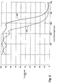
- the optical filters 282, 284, 286, and 288 have characteristics as shown in either FIG. 6 and or FIG. 7.
- the optical characteristic of each filter is chosen to block the laser beams of one wavelength while transmitting laser beams of a different wavelength.
- the filter of FIG. 6 substantially absorbs a beam at 680 nanometers while transmitting a beam at 625 nanometers.
- the filter of FIG. 7 absorbs a beam at 625 nanometers while transmitting a beam at 680 nanometers.
- the curve 406 represents the characteristics of the optical filter when light strikes at a 45° angle of incidence
- curve 408 represents the filter's characteristics when light strikes at a 60° angle of incidence.
- the locations of the polarizers and optical filters in FIG. 5 can be interchanged.
- the coaxially bundled beams are first split to produce two groups of beams. Each group is then applied to a polarizer. The beams from the polarizers are then resplit and applied to wavelength selective optical filters. The resulting four beams may then be input to one or more photoreceptors.
- Other embodiments are also possible and are meant to be included in the scope of this invention.
- each single laser beam (such as beam 214) can be replaced by plural laser beams (beneficially from a laser diode array) having similar wavelengths and polarizations.
- the multiple beams which replace each single beam must differ from the other multiple beams in either wavelength or polarization.
- Two laser diode arrays of N lasers each can be fabricated using staggered lasers grown on a grooved substrate as described in US-A-4,786,918. Four arrays of N lasers each can be obtained by combining two of those staggered arrays. Alternately, four laser diode arrays of N lasers each can be obtained by use of the integrated package described in US-A-5,371,526.
- Such other sections may include means for modulating the laser beams, a photoreceptive belt or drum, means for moving the photoreceptor, means for charging the photoreceptor, means for forming a latent image on the photoreceptor, means for transferring the latent image to paper, means for erasing the latent image from the photoreceptor, means for cleaning the photoreceptor, paper transport means, and means for fusing the image onto the paper.
Landscapes
- Physics & Mathematics (AREA)
- General Physics & Mathematics (AREA)
- Optics & Photonics (AREA)
- Engineering & Computer Science (AREA)
- Multimedia (AREA)
- Signal Processing (AREA)
- Mechanical Optical Scanning Systems (AREA)
- Facsimile Scanning Arrangements (AREA)
- Laser Beam Printer (AREA)
Claims (9)
- Rasterausgabescanvorrichtung mit:einer Einrichtung zum Erzeugen eines Bündels aus einem koaxial überlappenden ersten, zweiten, dritten und vierten Laserstrahl mit einer im wesentlichen gemeinsamen räumlichen Ursprungsposition, wobei der erste und der zweite Laserstrahl verschiedene Wellenlängen aber eine ähnliche erste Polarisation aufweisen, wobei der dritte und der vierte Laserstrahl verschiedene Wellenlängen, aber eine ähnliche zweite Polarisation aufweisen, wobei die zweite Polarisation im wesentlichen orthogonal zu der ersten Polarisation ausgerichtet ist, wobei der erste und der dritte Laserstrahl im wesentlichen dieselbe Wellenlänge aufweisen und wobei der zweite und der vierte Laserstrahl im wesentlichen dieselbe Wellenlänge aufweisen,einer Einrichtung zum Führen des Bündels,einem ersten Strahlenteiler zum Empfangen des geführten Bündels und zum Teilen des Bündels in eine erste und eine zweite Gruppe von Strahlen, die aus dem ersten, zweiten, dritten und vierten Laserstrahl erhalten werden,einem ersten Strahlentrenner zum Empfangen der ersten Gruppe von Strahlen, wobei der erste Strahlenteiler die Strahlen der ersten Gruppe, die aus dem dritten und dem vierten Laserstrahl erhalten werden, absorbiert und die Strahlen der ersten Gruppe, die aus dem ersten und dem zweiten Laserstrahl erhalten werden, auf einen ersten optischen Pfad richtet,einem zweiten Strahlenteiler zum Empfangen der Laserstrahlen auf dem ersten optischen Pfad, wobei der zweite Strahlenteiler die empfangenen Laserstrahlen in eine dritte und eine vierte Gruppe von Strahlen teilt, die aus dem ersten und dem zweiten Laserstrahl erhalten werden,und einen ersten optischen Filter zum Empfangen der dritten Gruppe von Strahlen, wobei der erste optische Filter die Strahlen der dritten Gruppe, die aus dem zweiten Laserstrahl erhalten werden, absorbiert und die Strahlen der dritten Gruppe, die aus dem ersten Laserstrahl erhalten werden, auf einen zweiten optischen Pfad richtet.
- Vorrichtung nach Anspruch 1, die weiterhin einen zweiten optischen Filter zum Empfangen der vierten Gruppe von Strahlen umfaßt, wobei der zweite optische Filter die Strahlen der vierten Gruppe, die aus dem ersten Laserstrahl erhalten werden, absorbiert und die Strahlen der vierten Gruppe, die aus dem zweiten Laserstrahl erhalten werden, auf einen dritten optischen Pfad richtet.
- Vorrichtung nach Anspruch 2, die weiterhin umfaßt: einen zweiten Strahlentrenner zum Empfangen der zweiten Gruppe von Strahlen, wobei der zweite Strahlentrenner die Strahlen der zweiten Gruppe, die aus dem ersten und dem zweiten Laserstrahl erhalten werden, absorbiert und die Strahlen der zweiten Gruppe, die aus dem dritten und vierten Laserstrahl erhalten werden, auf einen vierten optischen Pfad richtet, einen dritten Strahlenteiler zum Empfangen der strahlen auf dem vierten optischen Pfad, wobei der dritte Strahlenteiler die von ihm empfangenen Laserstrahlen in eine fünfte und eine sechste Gruppe von Strahlen teilt, die aus dem dritten und dem vierten Laserstrahl erhalten werden, einen dritten optischen Filter zum Empfangen der fünften Gruppe von Strahlen, wobei der dritte optische Filter die Strahlen der fünften Gruppe, die aus dem vierten Laserstrahl erhalten werden, absorbiert und die Strahlen der fünften Gruppe, die aus dem dritten Laserstrahl erhalten werden, auf einen fünften optischen Pfad richtet, und einen vierten optischen Filter zum Empfangen der sechsten Gruppe von Strahlen, wobei der vierte optische Filter die Strahlen der sechsten Gruppe, die von dem dritten Laserstrahl erhalten werden, absorbiert und die Strahlen der sechsten Gruppe, die von dem vierten Laserstrahl erhalten werden, auf einen sechsten optischen Pfad richtet.
- Vorrichtung nach Anspruch 3, die weiterhin einen oder mehrere Photorezeptoren sowie eine Einrichtung umfaßt, um die Laserstrahlen auf dem zweiten, dritten, vierten, fünften und sechsten optischen Pfad (1) jeweils auf den ersten, zweiten, dritten und vierten Photorezeptor oder (2) auf einen einzigen Photorezeptor zu richten.
- Vorrichtung nach wenigstens einem der Ansprüche 1 bis 4, die weiterhin eine Einrichtung zum Angleichen der optischen Pfadlängen von wenigstens zwei der Strahlen auf dem zweiten, dritten, fünften und sechsten optischen Pfad vom ersten Strahlenteiler zu dem Photorezeptor bzw. zu den entsprechenden Photorezeptoren umfaßt.
- Vorrichtung nach Anspruch 5, wobei die Angleichungseinrichtung einen Spiegel umfaßt.
- Rasterausgabescanvorrichtung miteiner Einrichtung zum Erzeugen eines Bündels aus einem koaxial überlappenden ersten, zweiten, dritten und vierten Laserstrahl mit einer im wesentlichen gemeinsamen räumlichen Ursprungsposition, wobei der erste und der zweite Laserstrahl verschiedene Wellenlängen aber eine ähnliche erste Polarisation aufweisen, wobei der dritte und der vierte Laserstrahl verschiedene Wellenlängen, aber eine ähnliche zweite Polarisation aufweisen, wobei die zweite Polarisation im wesentlichen orthogonal zu der ersten Polarisation ausgerichtet ist, wobei der erste und der dritte Laserstrahl im wesentlichen dieselbe Wellenlänge aufweisen und wobei der zweite und der vierte Laserstrahl im wesentlichen dieselbe Wellenlänge aufweisen,einer Einrichtung zum Führen des Bündels,einem ersten Strahlenteiler zum Empfangen des geführten Bündels und zum Teilen des Bündels in eine erste und eine zweite Gruppe von Strahlen, die aus dem ersten, zweiten, dritten und vierten Laserstrahl erhalten werden,einem ersten optischen Filter zum Empfangen der ersten Gruppe von Strahlen, wobei der erste Strahlenfilter die Strahlen der ersten Gruppe, die aus dem zweiten und dem vierten Laserstrahl erhalten werden, absorbiert und die Strahlen der ersten Gruppe, die aus dem ersten und dem dritten Laserstrahl erhalten werden, auf einen ersten optischen Pfad richtet,einem zweiten Strahlenteiler zum Empfangen der Laserstrahlen auf dem ersten optischen Pfad, wobei der zweite Strahlenteiler die empfangenen Laserstrahlen in eine dritte und eine vierte Gruppe von Strahlen teilt, die aus dem ersten und dem dritten Laserstrahl erhalten werden, undeinem ersten Strahlenteiler zum Empfangen der dritten Gruppe von Strahlen, wobei der erste Strahlenteiler den Strahl der dritten Gruppe, der aus dem dritten Laserstrahl erhalten wird, absorbiert und den Strahl der dritten Gruppe, der aus dem ersten Laserstrahl erhalten wird, auf einen zweiten optischen Pfad richtet.
- Verfahren zum Trennen von einzelnen Laserstrahlen eines geführten Bündels aus einem koaxial überlappenden und orthogonal polarisierten ersten, zweiten, dritten und vierten Laserstrahl, wobei der erste und der zweite Laserstrahl verschiedene Wellenlängen aber eine ähnliche erste Polarisation aufweisen, wobei der dritte und der vierte Laserstrahl verschiedene Wellenlängen, aber eine ähnliche zweite Polarisation aufweisen, wobei die zweite Polarisation im wesentlichen orthogonal zu der ersten Polarisation ausgerichtet ist, wobei der erste und der dritte Laserstrahl im wesentlichen dieselbe Wellenlänge aufweisen und wobei der zweite und der vierte Laserstrahl im wesentlichen dieselbe Wellenlänge aufweisen, wobei das Verfahren folgende Schritte umfaßt:Teilen des geführten Bündels in eine erste und eine zweite Gruppe von Strahlen, die aus dem ersten, zweiten, dritten und vierten Laserstrahl erhalten werden,Trennen des ersten und des zweiten Laserstrahls der ersten Gruppe von Strahlen, indem der erste und der vierte Laserstrahl absorbiert werden und indem die anderen Laserstrahlen auf einen ersten optischen Pfad gerichtet werden,Teilen der Laserstrahlen auf dem ersten optischen Pfad in eine dritte und eine vierte Gruppe von Strahlen, die aus dem ersten und dem zweiten Laserstrahl erhalten werden,Filtern des ersten Laserstrahls der dritten Gruppe von Strahlen, indem der zweite Laserstrahl absorbiert wird und indem der erste Laserstrahl auf einen zweiten optischen Pfad gerichtet wird,Filtern des zweiten Laserstrahls der vierten Gruppen von Strahlen, indem der erste Laserstrahl absorbiert wird und indem der zweite Laserstrahl auf einen dritten optischen Pfad gerichtet wird,Trennen des dritten und des vierten Laserstrahls der zweiten Gruppe von Strahlen, indem der erste und der zweite Laserstrahl absorbiert werden und indem die anderen Laserstrahlen auf einen vierten optischen Pfad gerichtet werden,Teilen der Laserstrahlen auf dem vierten optischen Pfad in eine fünfte und eine sechste Gruppe von Strahlen, die aus dem dritten und dem vierten Laserstrahl erhalten werden,Filtern des dritten Laserstrahls der fünften Gruppe von Strahlen, indem der vierte Laserstrahl absorbiert wird und indem der dritte Laserstrahl auf einen fünften optischen Pfad gerichtet wird, undFiltern des vierten Laserstrahls der sechsten Gruppe von Strahlen, indem der dritte Laserstrahl absorbiert wird und indem der vierte Laserstrahl auf einen sechsten optischen Pfad gerichtet wird.
- Verfahren zum Trennen von einzelnen Laserstrahlen eines Bündels aus einem geführten koaxial überlappenden und orthogonal polarisierten ersten, zweiten, dritten und vierten Laserstrahl, wobei der erste und der zweite Laserstrahl verschiedene Wellenlängen aber eine ähnliche erste Polarisation aufweisen, wobei der dritte und der vierte Laserstrahl verschiedene Wellenlängen, aber eine ähnliche zweite Polarisation aufweisen, wobei die zweite Polarisation im wesentlichen orthogonal zu der ersten Polarisation ausgerichtet ist, wobei der erste und der dritte Laserstrahl im wesentlichen dieselbe Wellenlänge aufweisen und wobei der zweite und der vierte Laserstrahl im wesentlichen dieselbe Wellenlänge aufweisen, wobei das Verfahren folgende Schritte umfaßt:Teilen des geführten Bündels in eine erste und eine zweite Gruppe von Strahlen, die aus dem ersten, zweiten, dritten und vierten Laserstrahl erhalten werden,Filtern des ersten und des dritten Laserstrahls der ersten Gruppe von Strahlen, indem der zweite und der vierte Laserstrahl absorbiert werden und indem die anderen Laserstrahlen auf einen ersten optischen Pfad gerichtet werden,Teilen der Laserstrahlen auf dem ersten optischen Pfad in eine dritte und eine vierte Gruppe von Strahlen, die aus dem ersten und dem zweiten Laserstrahl erhalten werden,Trennen des ersten Laserstrahls aus der dritten Gruppe von Strahlen, indem der dritte Laserstrahl absorbiert wird und indem der erste Laserstrahl auf einen zweiten optischen Pfad gerichtet wird,Trennen des dritten Laserstrahls aus der vierten Gruppen von Strahlen, indem der erste Laserstrahl absorbiert wird und indem der dritte Laserstrahl auf einen dritten optischen Pfad gerichtet wird,Filtern des zweiten und des vierten Laserstrahls aus der zweiten Gruppe von Strahlen, indem der erste und der dritte Laserstrahl absorbiert werden und indem die anderen Laserstrahlen auf einen vierten optischen Pfad gerichtet werden,Teilen der Laserstrahlen auf dem vierten optischen Pfad in eine fünfte und eine sechste Gruppe von Strahlen, die aus dem zweiten und dem vierten Laserstrahl erhalten werden,Trennen des zweiten Laserstrahls aus der fünften Gruppe von Strahlen, indem der vierte Laserstrahl absorbiert wird und indem der zweite Laserstrahl auf einen fünften optischen Pfad gerichtet wird, undTrennen des vierten Laserstrahls aus der sechsten Gruppe von Strahlen, indem der zweite Laserstrahl absorbiert wird und indem der vierte Laserstrahl auf einen sechsten optischen Pfad gerichtet wird.
Applications Claiming Priority (2)
| Application Number | Priority Date | Filing Date | Title |
|---|---|---|---|
| US995284 | 1992-12-22 | ||
| US07/995,284 US5325381A (en) | 1992-12-22 | 1992-12-22 | Multiple beam diode laser output scanning system |
Publications (3)
| Publication Number | Publication Date |
|---|---|
| EP0604077A2 EP0604077A2 (de) | 1994-06-29 |
| EP0604077A3 EP0604077A3 (de) | 1994-12-28 |
| EP0604077B1 true EP0604077B1 (de) | 1999-04-14 |
Family
ID=25541619
Family Applications (1)
| Application Number | Title | Priority Date | Filing Date |
|---|---|---|---|
| EP93309969A Expired - Lifetime EP0604077B1 (de) | 1992-12-22 | 1993-12-10 | Ausgangsabtastsystem mit mehrstrahligen Laserdioden |
Country Status (4)
| Country | Link |
|---|---|
| US (1) | US5325381A (de) |
| EP (1) | EP0604077B1 (de) |
| JP (1) | JPH06222297A (de) |
| DE (1) | DE69324457T2 (de) |
Families Citing this family (25)
| Publication number | Priority date | Publication date | Assignee | Title |
|---|---|---|---|---|
| US5402436A (en) * | 1993-12-29 | 1995-03-28 | Xerox Corporation | Nonmonolithic array structure of multiple beam diode lasers |
| US5563647A (en) * | 1994-10-24 | 1996-10-08 | Xerox Corporation | Method and apparatus for reducing differences in image heights of images generated by plural light beams having dissimilar wavelengths |
| US5691761A (en) * | 1994-12-02 | 1997-11-25 | Xerox Corporation | Method and apparatus for multi-channel printing in a raster output scanning system |
| US5528050A (en) * | 1995-07-24 | 1996-06-18 | Molecular Dynamics, Inc. | Compact scan head with multiple scanning modalities |
| DE19707834A1 (de) * | 1996-04-09 | 1997-10-16 | Zeiss Carl Fa | Materialbestrahlungsgerät und Verfahren zum Betrieb von Materialbestrahlungsgeräten |
| US5640473A (en) * | 1996-07-02 | 1997-06-17 | Gerber Systems Corporation | Method and apparatus for generating an optical beam for use in an imaging system |
| US5841567A (en) * | 1996-07-02 | 1998-11-24 | Barco Gerber Systems | Method and apparatus for imaging at a plurality of wavelengths |
| US5812322A (en) * | 1996-12-20 | 1998-09-22 | Eastman Kodak Company | Lenslet array system incorporating a field lenslet array |
| US5798867A (en) * | 1997-02-04 | 1998-08-25 | Miyachi Technos Corporation | Laser beam-splitting apparatus |
| US6188500B1 (en) * | 1998-04-03 | 2001-02-13 | Psc Scanning, Inc. | Method for generating multiple scan lines in a thin scanner |
| US6122404A (en) * | 1998-05-28 | 2000-09-19 | Trw Inc. | Visible stokes polarimetric imager |
| US6035079A (en) * | 1998-08-11 | 2000-03-07 | Trw Inc. | Saturable absorber based optical inverter |
| US6084717A (en) * | 1999-08-03 | 2000-07-04 | Health Research, Inc. | Laser beam splitter |
| TW494444B (en) | 1999-08-18 | 2002-07-11 | Semiconductor Energy Lab | Laser apparatus and laser annealing method |
| JP2001208998A (ja) * | 2000-01-27 | 2001-08-03 | Asahi Optical Co Ltd | レーザ描画装置 |
| JP2001326290A (ja) * | 2000-03-10 | 2001-11-22 | Seiko Epson Corp | パッケージの封止方法、電子素子モジュールの製造方法、封止装置並びにパッケージ品 |
| US6485599B1 (en) * | 2000-07-11 | 2002-11-26 | International Business Machines Corporation | Curing of sealants using multiple frequencies of radiation |
| US7830931B2 (en) * | 2005-06-02 | 2010-11-09 | Stc Inc. | Semiconductor laser excitation solid laser device and an image formation device having the same |
| CN101360460B (zh) * | 2006-01-20 | 2011-02-16 | 住友电气工业株式会社 | 摄像系统 |
| DE102006013929A1 (de) | 2006-03-21 | 2007-09-27 | Hauni Maschinenbau Ag | Perforationsvorrichtung der tabakverarbeitenden Industrie zum Perforieren einer Umhüllung eines stabförmigen Artikels |
| JP4935278B2 (ja) * | 2006-09-28 | 2012-05-23 | 富士ゼロックス株式会社 | 表面発光型半導体アレイ素子、モジュール、光源装置、情報処理装置、光送信装置、光空間伝送装置、および光空間伝送システム |
| KR20080062381A (ko) * | 2006-12-29 | 2008-07-03 | 삼성전자주식회사 | 광주사장치 및 이를 채용한 화상형성장치 |
| US20090120916A1 (en) * | 2007-11-12 | 2009-05-14 | L3 Communications Corporation | Through-Via Laser Reflow Systems And Methods For Surface Mount Components |
| WO2012099151A1 (ja) * | 2011-01-18 | 2012-07-26 | オリンパス株式会社 | 光走査装置および走査型検査装置 |
| CN103358555A (zh) * | 2012-03-30 | 2013-10-23 | 通用电气公司 | 用于激光快速成型加工设备的多束激光扫描系统及方法 |
Family Cites Families (17)
| Publication number | Priority date | Publication date | Assignee | Title |
|---|---|---|---|---|
| US3690756A (en) * | 1971-03-22 | 1972-09-12 | Xerox Corp | Color xerography |
| US4474422A (en) * | 1979-11-13 | 1984-10-02 | Canon Kabushiki Kaisha | Optical scanning apparatus having an array of light sources |
| JPS57102609A (en) * | 1980-12-18 | 1982-06-25 | Canon Inc | Method and device for scanning using plural number of beams |
| JPS5895361A (ja) * | 1981-12-01 | 1983-06-06 | Canon Inc | カラー画像形成装置 |
| ATE24081T1 (de) * | 1982-01-19 | 1986-12-15 | Cavendish Dwight Holdings Ltd | Licht-projektionsapparat. |
| US4445125A (en) * | 1982-04-19 | 1984-04-24 | Xerox Corporation | Diode laser array system for printing and copying applications |
| JPS5912416A (ja) * | 1982-07-14 | 1984-01-23 | Ricoh Co Ltd | 多ビ−ム光走査装置 |
| US4761046A (en) * | 1985-05-02 | 1988-08-02 | Ricoh Company, Ltd. | Laser beam recording method |
| JPS63120261U (de) * | 1987-01-30 | 1988-08-03 | ||
| DE3854093T2 (de) * | 1987-04-28 | 1995-11-16 | Canon Kk | Multibilderzeugungsgerät. |
| US4873541A (en) * | 1987-05-28 | 1989-10-10 | Canon Kabushiki Kaisha | Image forming apparatus |
| JPH0283518A (ja) * | 1988-09-20 | 1990-03-23 | Minolta Camera Co Ltd | レーザビーム走査装置 |
| US5068677A (en) * | 1988-09-20 | 1991-11-26 | Minolta Camera Kabushiki Kaisha | Laser scanner with selected plural beam sources |
| JPH03248115A (ja) * | 1990-02-26 | 1991-11-06 | Minolta Camera Co Ltd | マルチビーム光学装置 |
| US5113279A (en) * | 1990-03-19 | 1992-05-12 | Minolta Camera Kabushiki Kaisha | Laser beam scanning apparatus |
| JP2995925B2 (ja) * | 1991-06-14 | 1999-12-27 | ミノルタ株式会社 | レーザビーム合成方法 |
| US5243359A (en) * | 1991-12-19 | 1993-09-07 | Xerox Corporation | Raster output scanner for a multistation xerographic printing system |
-
1992
- 1992-12-22 US US07/995,284 patent/US5325381A/en not_active Expired - Lifetime
-
1993
- 1993-11-12 JP JP5283251A patent/JPH06222297A/ja active Pending
- 1993-12-10 EP EP93309969A patent/EP0604077B1/de not_active Expired - Lifetime
- 1993-12-10 DE DE69324457T patent/DE69324457T2/de not_active Expired - Lifetime
Also Published As
| Publication number | Publication date |
|---|---|
| JPH06222297A (ja) | 1994-08-12 |
| EP0604077A2 (de) | 1994-06-29 |
| DE69324457D1 (de) | 1999-05-20 |
| EP0604077A3 (de) | 1994-12-28 |
| US5325381A (en) | 1994-06-28 |
| DE69324457T2 (de) | 1999-10-07 |
Similar Documents
| Publication | Publication Date | Title |
|---|---|---|
| US5325381A (en) | Multiple beam diode laser output scanning system | |
| US5243359A (en) | Raster output scanner for a multistation xerographic printing system | |
| EP1361069B1 (de) | Farblaserdrucker | |
| US7705872B2 (en) | Optical writing device and image forming apparatus | |
| US5956070A (en) | Color xerographic printer with multiple linear arrays of surface emitting lasers with dissimilar polarization states and dissimilar wavelengths | |
| JP2995925B2 (ja) | レーザビーム合成方法 | |
| US5371526A (en) | Raster output scanner for a single pass printing system which separates plural laser beams by wavelength and polarization | |
| JPH02179603A (ja) | 多ビーム走査装置 | |
| US5343224A (en) | Diode laser multiple output scanning system | |
| US5341158A (en) | Raster output scanner for a xerographic printing system having laser diodes arranged in a line parallel to the fast scan direction | |
| EP0710009B1 (de) | Verfahren und Vorrichtung, um den Unterschied der Bildhöhen von Bildern, die durch mehrere Lichtstrahlen mit verschiedenen Höhen erzeugt werden, zu reduzieren | |
| US5691761A (en) | Method and apparatus for multi-channel printing in a raster output scanning system | |
| US5995267A (en) | Time division multiplexing multiple beam raster output scanning system | |
| US6873445B2 (en) | Optical multi-beam scanning device and image forming apparatus | |
| EP2360508B1 (de) | Polarisiertes Mehrstrahllaserabtastsystem mit mehreren Quellen | |
| JP5754617B2 (ja) | 光走査装置及び画像形成装置 | |
| US7151624B2 (en) | Light scanning unit | |
| EP0782328A2 (de) | Rasterausgabeabtastsystem mit mehreren Strahlen mit Polarisationsmultiplexierung | |
| WO1998047037A1 (en) | High duty cycle scanner for laser printer | |
| JPH06160743A (ja) | レーザビーム走査装置 | |
| EP0781663B1 (de) | Farbxerographischer Drucker mit vielfachen linearen Reihen von oberflächenemittierenden Lasern mit verschiedenen Wellenlängen | |
| JPH085944A (ja) | マルチビーム光学装置 | |
| JPH0829713A (ja) | マルチビーム走査光学装置 |
Legal Events
| Date | Code | Title | Description |
|---|---|---|---|
| PUAI | Public reference made under article 153(3) epc to a published international application that has entered the european phase |
Free format text: ORIGINAL CODE: 0009012 |
|
| AK | Designated contracting states |
Kind code of ref document: A2 Designated state(s): DE FR GB |
|
| PUAL | Search report despatched |
Free format text: ORIGINAL CODE: 0009013 |
|
| AK | Designated contracting states |
Kind code of ref document: A3 Designated state(s): DE FR GB |
|
| 17P | Request for examination filed |
Effective date: 19950628 |
|
| 17Q | First examination report despatched |
Effective date: 19970411 |
|
| GRAG | Despatch of communication of intention to grant |
Free format text: ORIGINAL CODE: EPIDOS AGRA |
|
| GRAG | Despatch of communication of intention to grant |
Free format text: ORIGINAL CODE: EPIDOS AGRA |
|
| GRAH | Despatch of communication of intention to grant a patent |
Free format text: ORIGINAL CODE: EPIDOS IGRA |
|
| GRAH | Despatch of communication of intention to grant a patent |
Free format text: ORIGINAL CODE: EPIDOS IGRA |
|
| GRAG | Despatch of communication of intention to grant |
Free format text: ORIGINAL CODE: EPIDOS AGRA |
|
| GRAH | Despatch of communication of intention to grant a patent |
Free format text: ORIGINAL CODE: EPIDOS IGRA |
|
| GRAA | (expected) grant |
Free format text: ORIGINAL CODE: 0009210 |
|
| AK | Designated contracting states |
Kind code of ref document: B1 Designated state(s): DE FR GB |
|
| REF | Corresponds to: |
Ref document number: 69324457 Country of ref document: DE Date of ref document: 19990520 |
|
| ET | Fr: translation filed | ||
| PLBE | No opposition filed within time limit |
Free format text: ORIGINAL CODE: 0009261 |
|
| STAA | Information on the status of an ep patent application or granted ep patent |
Free format text: STATUS: NO OPPOSITION FILED WITHIN TIME LIMIT |
|
| 26N | No opposition filed | ||
| REG | Reference to a national code |
Ref country code: GB Ref legal event code: IF02 |
|
| PGFP | Annual fee paid to national office [announced via postgrant information from national office to epo] |
Ref country code: DE Payment date: 20121122 Year of fee payment: 20 |
|
| PGFP | Annual fee paid to national office [announced via postgrant information from national office to epo] |
Ref country code: GB Payment date: 20121122 Year of fee payment: 20 |
|
| PGFP | Annual fee paid to national office [announced via postgrant information from national office to epo] |
Ref country code: FR Payment date: 20130130 Year of fee payment: 20 |
|
| REG | Reference to a national code |
Ref country code: DE Ref legal event code: R071 Ref document number: 69324457 Country of ref document: DE |
|
| REG | Reference to a national code |
Ref country code: GB Ref legal event code: PE20 Expiry date: 20131209 |
|
| PG25 | Lapsed in a contracting state [announced via postgrant information from national office to epo] |
Ref country code: DE Free format text: LAPSE BECAUSE OF EXPIRATION OF PROTECTION Effective date: 20131211 Ref country code: GB Free format text: LAPSE BECAUSE OF EXPIRATION OF PROTECTION Effective date: 20131209 |