EP0604251A1 - Antriebseinrichtung für die Spielnachstellung einer Trommelbremse - Google Patents
Antriebseinrichtung für die Spielnachstellung einer Trommelbremse Download PDFInfo
- Publication number
- EP0604251A1 EP0604251A1 EP93402855A EP93402855A EP0604251A1 EP 0604251 A1 EP0604251 A1 EP 0604251A1 EP 93402855 A EP93402855 A EP 93402855A EP 93402855 A EP93402855 A EP 93402855A EP 0604251 A1 EP0604251 A1 EP 0604251A1
- Authority
- EP
- European Patent Office
- Prior art keywords
- cable
- stud
- disc
- guide
- return member
- Prior art date
- Legal status (The legal status is an assumption and is not a legal conclusion. Google has not performed a legal analysis and makes no representation as to the accuracy of the status listed.)
- Granted
Links
- 230000000295 complement effect Effects 0.000 claims abstract description 30
- 238000004804 winding Methods 0.000 claims description 17
- 230000002093 peripheral effect Effects 0.000 claims description 6
- 230000000694 effects Effects 0.000 claims description 3
- 230000003100 immobilizing effect Effects 0.000 claims description 3
- 125000006850 spacer group Chemical group 0.000 description 3
- 241001417494 Sciaenidae Species 0.000 description 1
- 238000004026 adhesive bonding Methods 0.000 description 1
- 238000005452 bending Methods 0.000 description 1
- 238000006073 displacement reaction Methods 0.000 description 1
- 238000003466 welding Methods 0.000 description 1
Images

Classifications
-
- F—MECHANICAL ENGINEERING; LIGHTING; HEATING; WEAPONS; BLASTING
- F16—ENGINEERING ELEMENTS AND UNITS; GENERAL MEASURES FOR PRODUCING AND MAINTAINING EFFECTIVE FUNCTIONING OF MACHINES OR INSTALLATIONS; THERMAL INSULATION IN GENERAL
- F16D—COUPLINGS FOR TRANSMITTING ROTATION; CLUTCHES; BRAKES
- F16D65/00—Parts or details
- F16D65/38—Slack adjusters
- F16D65/40—Slack adjusters mechanical
- F16D65/52—Slack adjusters mechanical self-acting in one direction for adjusting excessive play
- F16D65/56—Slack adjusters mechanical self-acting in one direction for adjusting excessive play with screw-thread and nut
- F16D65/561—Slack adjusters mechanical self-acting in one direction for adjusting excessive play with screw-thread and nut for mounting within the confines of a drum brake
- F16D65/565—Slack adjusters mechanical self-acting in one direction for adjusting excessive play with screw-thread and nut for mounting within the confines of a drum brake arranged diametrically opposite to service brake actuator, and subjected to service brake force
Definitions
- the present invention relates to a device for controlling a backlash device for a drum brake.
- a drum brake for a motor vehicle comprises a drum, integral with a vehicle wheel, and a plate, integral with an axle of the vehicle, forming a support for two jaws provided with linings intended to cooperate by friction with the internal surface of the drum when the brake is applied.
- a device for controlling a play take-up device for a drum brake is already known in the prior art, of the type comprising an actuating lever for the play take-up device, carried by a first brake shoe, a cable connected by a first end to this lever and by a second end to the second brake shoe, and a cable return member carried by the first shoe.
- the actuating lever comprises elastic means for returning to the rest position making it possible to keep the cable taut.
- the invention aims to precisely adjust the initial position of the lever and the initial tension of the cable, this with simple and easy to implement means.
- the subject of the invention is a device for controlling a backlash device for a drum brake, of the aforementioned type, characterized in that the return member is hooked on the first jaw by fitting a stud, carried by one of these two elements, in a complementary orifice, formed in the other of these two elements, the stud and the complementary orifice comprising means for relative angular positioning, the return member comprising a curved guide for winding the cable, of center of curvature eccentric with respect to the axis of the stud or of the complementary hole, so that the cable tension is a function of the angular position of the stud in the complementary hole.
- FIG. 1 shows a drum brake for a motor vehicle, designated by the general reference 10, comprising, in a conventional manner, a drum 12, secured to a wheel of the vehicle, and a plate 14 secured to an axle of the vehicle.
- This plate 14 forms a support for two jaws 16,18 provided with linings 20,22 intended to cooperate by friction with the internal surface 12I of the drum 12 when the brake is actuated.
- a cylinder 24 for spacing the jaws 16.18 is interposed between two ends 16A, 18A facing the jaws 16.18.
- a play take-up device 26 is interposed between the two other ends 16B, 18B facing the jaws 16,18.
- this device 26 comprises a spacer 28, of variable length, connected by its ends to the jaws 16, 18, and a ratchet wheel 30 for adjusting the length of the spacer 28, driven by a pawl 32 carried by a leaf spring 34.
- This leaf 34 is fixed by one of its ends to the spacer 28.
- a spring 36 connected by its ends to the two jaws 16,18, resiliently biases the latter towards one another.
- FIG. 1 also shows a device 38, according to the invention, for controlling the play take-up device 26.
- This device 38 comprises a cable 40 connected by a first end 40A to a lever 42 for actuating the play take-up device 26, articulated on a first jaw 16, and by a second end 40B to the second jaw 18.
- a return member 44 is carried by the first jaw 16 and cooperates with the middle part of the cable 40 so as to form two substantially perpendicular cable strands.
- the free end 42A of the lever 42 is intended to cooperate with the free end 34A of the leaf spring 34 so as to actuate the pawl 32 for driving the ratchet wheel 30 by displacement of the lever 42.
- the leaf spring 34 allows on the one hand to elastically urge the lever 42 towards a rest position, and on the other hand to keep the cable 40 taut.
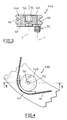
- the return member 44 comprises a disc 46, of axis X, provided with an annular groove 48, formed in its outline, forming cable winding guide 40.
- the return member 44 further comprises a latching stud 50, integral with the disc 46, of axis Y eccentric relative to the axis X of this disc 46.
- the stud 50 is intended to be fitted into a complementary orifice 52 formed in the first jaw 16.
- contours of the pad 50 and the complementary orifice 52 are delimited respectively by grooved complementary surfaces 50A, 52A forming means for relative angular positioning.
- the free end of the stud 50 is delimited by a centering surface 54 facilitating the positioning and fitting of the stud 50 in the complementary orifice 52.
- a recess 56 formed in the face of the disc 46 opposite the pad 50, delimited by attachment surfaces of a tool, of known type, for positioning the return member 44 on the jaw 16.
- the curved guide 48 for winding the cable 40 has a center of curvature eccentric with respect to the axis Y of the pad so that the cable tension is a function of the angular position of the pad 50 in the complementary orifice 52.
- the initial tension of the cable 40 and the initial position of the lever 42 are adjusted as follows.
- the pad 50 is placed in line with the fitting hole 52, the axis X of the disc 46 being arranged as close as possible to the axis R of rotation of the drum 12, this axis R being shown. by a cross in FIG. 1, then the cable 40 is engaged in the curved guide 48. In this position of the return member 44, the tension of the cable 40 is minimal.
- the deflection member 44 is rotated around the axis Y of the stud 50, for example by means of a tool hooked into the recess 56, so as to obtain a tension of the cable 40 adapted for the operation of the backlash device 26.
- the stud 50 When the tension of the cable 40 is adjusted, the stud 50 is fitted into the complementary orifice 52, this stud 50 being immobilized in rotation by cooperation of the grooved surfaces 50A, 52A.
- the disc 46A is rotatably mounted around a pivot 58 carried by a support 60 integral with the stud 50. Furthermore, the recess 56 for attaching the tool is formed in the free end of the pivot 58 .
- a sleeve 62 made of a material with a low coefficient of friction, is interposed between the pivot 58 and the disc 46A.
- the establishment on the jaw 16 of the return member 44A according to the second embodiment is done analogously to the first embodiment.
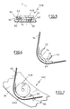
- the disc 46B is integral with the attachment stud 50.
- the return member 44B further comprises a guide 64 delimiting a curved groove 66 for winding the cable 40, extending around the contour of the disc 46B so that the center of curvature of the groove 66 is eccentric with respect to the Y axis of pad 50.
- the guide 64 is supported on a recess 68 of the contour of the disc 46B, under the effect of the tension of the cable 40, by means of a connecting member 70 of complementary shape, integral with the guide 64.
- connecting member 70 comprises two branches 72, 74 delimiting between them a circular bearing surface 76, of shape complementary to the recess 68 , preferably extending over 180 °.
- the connecting member 70 is fixed to the guide 64 by known means, for example by welding or by gluing.
- the guide 64 is immobilized along the axis X of the disc 46B by interlocking between the shoulder 80 formed by the recess 68 and the face 82 of the jaw 16 opposite this shoulder 80.
- the immobilization of the guide 64 in rotation around the axis X of the disc 46B is ensured by the adhesion of the surfaces in mutual support of the disc 46B and the connecting member 70.
- the connecting member 70 is glued to the disc 46B after adjusting the position of the return member 44B and fixing it on the jaw 16.
- the cable winding guide 64 has a radius of curvature greater than that of the previous embodiments, which makes it possible to reduce the bending of the cable and to obtain a better efficiency of movement of this cable.
- the positioning on the jaw 16 of the return member 44B is done in a similar manner to the previous embodiments, after having interposed the guide 64 between the cable 40 and the contour of the disc 46B.
- the guide 64A includes a projection 84 intended to be fitted into a recess 86 for immobilizing the guide in rotation, formed in the jaw 16.
- the guide 64A is immobilized in rotation by fitting the projection 84 into the recess 86 while the disc 46B can be moved in rotation to adjust the eccentricity of the return member. 44C.
- the return member can be hung on the corresponding jaw by fitting a stud secured to this jaw in a complementary orifice formed in the return member.
- grooved surfaces of relative angular positioning of the attachment stud and of the complementary orifice can be replaced by knurled surfaces or equivalent means.
- the invention has many advantages.
Landscapes
- Engineering & Computer Science (AREA)
- General Engineering & Computer Science (AREA)
- Mechanical Engineering (AREA)
- Braking Arrangements (AREA)
- Flexible Shafts (AREA)
Applications Claiming Priority (2)
| Application Number | Priority Date | Filing Date | Title |
|---|---|---|---|
| FR9215645 | 1992-12-23 | ||
| FR9215645A FR2699629B1 (fr) | 1992-12-23 | 1992-12-23 | Dispositif de commande d'un dispositif de rattrapage de jeu pour frein à tambour. |
Publications (2)
| Publication Number | Publication Date |
|---|---|
| EP0604251A1 true EP0604251A1 (de) | 1994-06-29 |
| EP0604251B1 EP0604251B1 (de) | 1997-03-05 |
Family
ID=9437058
Family Applications (1)
| Application Number | Title | Priority Date | Filing Date |
|---|---|---|---|
| EP19930402855 Expired - Lifetime EP0604251B1 (de) | 1992-12-23 | 1993-11-24 | Antriebseinrichtung für die Spielnachstellung einer Trommelbremse |
Country Status (3)
| Country | Link |
|---|---|
| EP (1) | EP0604251B1 (de) |
| DE (1) | DE69308516T2 (de) |
| FR (1) | FR2699629B1 (de) |
Citations (2)
| Publication number | Priority date | Publication date | Assignee | Title |
|---|---|---|---|---|
| GB966076A (en) * | 1962-01-02 | 1964-08-06 | Bendix Corp | Automatic brake adjuster |
| US3184008A (en) * | 1963-05-15 | 1965-05-18 | Bendix Corp | Automatic adjuster for non-servo brake |
-
1992
- 1992-12-23 FR FR9215645A patent/FR2699629B1/fr not_active Expired - Fee Related
-
1993
- 1993-11-24 DE DE1993608516 patent/DE69308516T2/de not_active Expired - Fee Related
- 1993-11-24 EP EP19930402855 patent/EP0604251B1/de not_active Expired - Lifetime
Patent Citations (2)
| Publication number | Priority date | Publication date | Assignee | Title |
|---|---|---|---|---|
| GB966076A (en) * | 1962-01-02 | 1964-08-06 | Bendix Corp | Automatic brake adjuster |
| US3184008A (en) * | 1963-05-15 | 1965-05-18 | Bendix Corp | Automatic adjuster for non-servo brake |
Also Published As
| Publication number | Publication date |
|---|---|
| EP0604251B1 (de) | 1997-03-05 |
| FR2699629A1 (fr) | 1994-06-24 |
| DE69308516D1 (de) | 1997-04-10 |
| DE69308516T2 (de) | 1997-07-17 |
| FR2699629B1 (fr) | 1995-03-24 |
Similar Documents
| Publication | Publication Date | Title |
|---|---|---|
| EP1565666B1 (de) | Trommelbremse und bremsbacke für solch eine bremse | |
| EP2072850A1 (de) | Montagesystem für Bremsbelagträger von Scheibenbremsen | |
| EP2088346B1 (de) | Führung der Halterung eines Bremsklotzes von Scheibenbremsen | |
| EP0486341B1 (de) | Mechanisch betätigbare Trommelbremse | |
| EP0734496B1 (de) | Automatisch nachstellbare strebe für eine trommelbremse | |
| EP0604251B1 (de) | Antriebseinrichtung für die Spielnachstellung einer Trommelbremse | |
| EP0069657B1 (de) | Trommelbremse | |
| FR2725485A1 (fr) | Embrayage a friction a compensation d'usure des garnitures de friction | |
| EP0077726B1 (de) | Trommelbremse und Strebenteil für eine derartige Bremse | |
| EP0546927A1 (de) | Handbremshebel für eine Parkbremse | |
| EP0146444B1 (de) | Verankerung eines Verstrebungselementes, welches eine Einrichtung zur automatischen Regelung für ein Bremsbackensegment aufweist | |
| EP0254629B1 (de) | Feder für eine Trommelbremsanordnung | |
| EP0061961A1 (de) | Trommelbremse mit selbsttätiger Nachstellung | |
| FR2499188A1 (fr) | Frein a tambour | |
| FR2496802A1 (fr) | Dispositif d'appui de freins a machoires interieures a mecanisme automatique de recul pour remorque a freinage a inertie | |
| EP0439977B1 (de) | Keilbetätigte Scheibenbremse | |
| EP0003452B1 (de) | Trommelbremse | |
| EP0642634B1 (de) | Trommelbremse mit hilfseinrichtung zum automatischen nachstellen | |
| EP0799144B1 (de) | Bremsvorrichtung für schienenfahrzeug | |
| FR2938313A1 (fr) | Mecanisme de frein a tambour. | |
| FR2723731A1 (fr) | Dispositif de tension d'une chaine d'entrainement sans fin, notamment pour transporteur. | |
| FR2697880A1 (fr) | Dispositif de rattrapage de jeu pour frein à tambour et frein muni d'un tel dispositif. | |
| FR2841951A1 (fr) | Dispositif de rattrapage automatique d'usure de frein a tambour, frein et lot munis de ce dispositif | |
| WO2002030724A1 (fr) | Frein a main de vehicule automobile | |
| FR2958902A1 (fr) | Agencement de compensation de freinage de vehicule automobile |
Legal Events
| Date | Code | Title | Description |
|---|---|---|---|
| PUAI | Public reference made under article 153(3) epc to a published international application that has entered the european phase |
Free format text: ORIGINAL CODE: 0009012 |
|
| AK | Designated contracting states |
Kind code of ref document: A1 Designated state(s): DE GB IT |
|
| 17P | Request for examination filed |
Effective date: 19941207 |
|
| 17Q | First examination report despatched |
Effective date: 19950906 |
|
| GRAG | Despatch of communication of intention to grant |
Free format text: ORIGINAL CODE: EPIDOS AGRA |
|
| GRAH | Despatch of communication of intention to grant a patent |
Free format text: ORIGINAL CODE: EPIDOS IGRA |
|
| GRAH | Despatch of communication of intention to grant a patent |
Free format text: ORIGINAL CODE: EPIDOS IGRA |
|
| GRAA | (expected) grant |
Free format text: ORIGINAL CODE: 0009210 |
|
| AK | Designated contracting states |
Kind code of ref document: B1 Designated state(s): DE GB IT |
|
| GBT | Gb: translation of ep patent filed (gb section 77(6)(a)/1977) |
Effective date: 19970317 |
|
| REF | Corresponds to: |
Ref document number: 69308516 Country of ref document: DE Date of ref document: 19970410 |
|
| ITF | It: translation for a ep patent filed | ||
| PLBE | No opposition filed within time limit |
Free format text: ORIGINAL CODE: 0009261 |
|
| STAA | Information on the status of an ep patent application or granted ep patent |
Free format text: STATUS: NO OPPOSITION FILED WITHIN TIME LIMIT |
|
| 26N | No opposition filed | ||
| PGFP | Annual fee paid to national office [announced via postgrant information from national office to epo] |
Ref country code: DE Payment date: 19981026 Year of fee payment: 6 |
|
| PGFP | Annual fee paid to national office [announced via postgrant information from national office to epo] |
Ref country code: GB Payment date: 19981117 Year of fee payment: 6 |
|
| PG25 | Lapsed in a contracting state [announced via postgrant information from national office to epo] |
Ref country code: GB Free format text: LAPSE BECAUSE OF NON-PAYMENT OF DUE FEES Effective date: 19991124 |
|
| GBPC | Gb: european patent ceased through non-payment of renewal fee |
Effective date: 19991124 |
|
| PG25 | Lapsed in a contracting state [announced via postgrant information from national office to epo] |
Ref country code: DE Free format text: LAPSE BECAUSE OF NON-PAYMENT OF DUE FEES Effective date: 20000901 |
|
| PG25 | Lapsed in a contracting state [announced via postgrant information from national office to epo] |
Ref country code: IT Free format text: LAPSE BECAUSE OF NON-PAYMENT OF DUE FEES;WARNING: LAPSES OF ITALIAN PATENTS WITH EFFECTIVE DATE BEFORE 2007 MAY HAVE OCCURRED AT ANY TIME BEFORE 2007. THE CORRECT EFFECTIVE DATE MAY BE DIFFERENT FROM THE ONE RECORDED. Effective date: 20051124 |