EP0604263A1 - Stellglied zur Bewegung einer schwenkbaren Raketendüse - Google Patents
Stellglied zur Bewegung einer schwenkbaren Raketendüse Download PDFInfo
- Publication number
- EP0604263A1 EP0604263A1 EP93402963A EP93402963A EP0604263A1 EP 0604263 A1 EP0604263 A1 EP 0604263A1 EP 93402963 A EP93402963 A EP 93402963A EP 93402963 A EP93402963 A EP 93402963A EP 0604263 A1 EP0604263 A1 EP 0604263A1
- Authority
- EP
- European Patent Office
- Prior art keywords
- chamber
- distributor
- conduit
- rod
- passage
- Prior art date
- Legal status (The legal status is an assumption and is not a legal conclusion. Google has not performed a legal analysis and makes no representation as to the accuracy of the status listed.)
- Granted
Links
- 238000004891 communication Methods 0.000 claims abstract description 21
- 239000012530 fluid Substances 0.000 claims abstract description 17
- 238000011144 upstream manufacturing Methods 0.000 claims description 19
- OKTJSMMVPCPJKN-UHFFFAOYSA-N Carbon Chemical compound [C] OKTJSMMVPCPJKN-UHFFFAOYSA-N 0.000 claims description 3
- 229910002804 graphite Inorganic materials 0.000 claims description 3
- 239000010439 graphite Substances 0.000 claims description 3
- 239000000463 material Substances 0.000 claims description 3
- 208000031968 Cadaver Diseases 0.000 description 5
- 210000000056 organ Anatomy 0.000 description 4
- 238000012550 audit Methods 0.000 description 3
- 235000021183 entrée Nutrition 0.000 description 3
- 238000002485 combustion reaction Methods 0.000 description 2
- 238000006073 displacement reaction Methods 0.000 description 2
- 238000007789 sealing Methods 0.000 description 2
- 230000003749 cleanliness Effects 0.000 description 1
- 238000010276 construction Methods 0.000 description 1
- 230000004064 dysfunction Effects 0.000 description 1
- 230000005484 gravity Effects 0.000 description 1
- 238000012423 maintenance Methods 0.000 description 1
- 238000004519 manufacturing process Methods 0.000 description 1
- 238000012986 modification Methods 0.000 description 1
- 230000004048 modification Effects 0.000 description 1
- 230000007935 neutral effect Effects 0.000 description 1
- 239000004449 solid propellant Substances 0.000 description 1
Images



Classifications
-
- F—MECHANICAL ENGINEERING; LIGHTING; HEATING; WEAPONS; BLASTING
- F42—AMMUNITION; BLASTING
- F42B—EXPLOSIVE CHARGES, e.g. FOR BLASTING, FIREWORKS, AMMUNITION
- F42B10/00—Means for influencing, e.g. improving, the aerodynamic properties of projectiles or missiles; Arrangements on projectiles or missiles for stabilising, steering, range-reducing, range-increasing or fall-retarding
- F42B10/60—Steering arrangements
- F42B10/66—Steering by varying intensity or direction of thrust
- F42B10/663—Steering by varying intensity or direction of thrust using a plurality of transversally acting auxiliary nozzles, which are opened or closed by valves
Definitions
- the present invention relates to a device for actuating a mechanical member from a fluid supply source.
- the device according to the invention is more particularly intended for piloting, in particular in force, aircraft such as for example missiles.
- a control unit comprising a plurality of lateral nozzles which are distributed around the structure of said missile and whose flow of the gas jet can be deflected by a mechanical member associated with each lateral nozzle and controlled by an actuating device.
- the latter generally comprises a controllable distributor capable of being traversed by the gas jet coming from the main propulsion generator of the missile or from an auxiliary generator, and supplying the nozzles.
- the distributor acts, by means of the gas jet, on the mechanical member which makes it possible, by its change of position, to deflect the gas jet at the outlet of the corresponding lateral nozzle, so as to modify the trajectory of the missile.
- the object of the present invention is to remedy these drawbacks.
- the piston when the distributor is active, closing for example the communication between the first conduit connected to the outlet orifice, and said chamber of said distributor, the piston is in the retracted position for which said member occupies a first operating position, under the action of the fluid source acting in the second chamber of the jack through the third conduit, which empties the first chamber of the jack outward through the second conduit, the chamber of said distributor and the outlet orifice of the body.
- the distributor when the distributor 'is inactive, then putting the second conduit into communication with the first conduit, via the distributor chamber, the piston slides to its extended position for which said member occupies a second operating position, under the action of the fluid source acting in the first chamber of the jack, which empties then the second bedroom through the third conduit.
- the device according to the invention overcomes the aforementioned drawbacks, since it allows said chamber of the distributor to be placed in communication with the gas jet only sequentially, that is to say only when the organ must be controlled to divert the flow of the gas jet leaving the nozzle, and since it completely isolates the organ to be controlled from the jet or gas flow emitted by the fluid source, such as the missile propulsion generator.
- the first position of said member associated with one of the lateral nozzles of the missile does not affect the trajectory of the missile, since the gas jet does not pass through the chamber of the device and therefore does not act on the piston of the jack , while the second position of said member makes it possible to deflect the flow of the gaseous jet at the outlet of the nozzle then modifying the trajectory of said missile.
- said actuating device in the form of a body uniting the jack and the distributor thus constitutes a construction unit, facilitating its practical realization, as well as the assembly and disassembly operations with a view to its maintenance or of his replacement.
- the cross section of the first chamber of said cylinder is greater than the annular cross section of the second chamber of the piston, defined by the difference in surfaces between the head and the rod of said piston.
- the difference in piston cross-sections in the two chambers allows, during operation of the distributor, the exit of said piston despite an identical pressure from the gas flow in the two chambers.
- seals are provided between said piston and said chambers and they are made of a material resistant to high temperatures and pressures. For example, graphite seals are particularly suitable for this type of application.
- said connecting means between said piston and said member may be constituted by at least one articulation with an axis, ball joint or the like, capable of causing said member to move from a first position to a second position, and vice versa, by following the sliding of said piston.
- said connecting means between said piston and said member may be constituted by at least one articulation with an axis, ball joint or the like, capable of causing said member to move from a first position to a second position, and vice versa, by following the sliding of said piston.
- said distributor comprises a controllable electromagnet, connected to said body, and an axially displaceable element comprising a rod which passes through an axial passage, formed in said body and comprising said chamber, said rod having a shoulder situated at the level of said chamber of said axial passage and capable of cooperating either with an upstream bearing surface of said passage, through which opens said first conduit, when said electromagnet is excited, or with a downstream bearing surface of said passage, opening towards said body outlet orifice , when said electromagnet is de-energized.
- the contact of the shoulder of the rod with the upstream range or the downstream range of the passage closes, respectively, the first supply duct of said distributor chamber, the second distributor discharge duct being in communication with the outlet or exhaust port, or the outlet port of said chamber of the distributor, the first conduit being in communication with the second conduit.
- the diameter of said shoulder is slightly greater than the internal diameters of the upstream and downstream spans of said passage, while the diameter of said rod is slightly less than those of said spans.
- said outlet orifice of said body is coaxial with said passage and extends the downstream reach of said passage, and the rod ends, at its end opposite to that facing the electromagnet, by a cylindrical tip whose diameter is close of the diameter of said rod and which is located in said outlet orifice.
- the outlet orifice of the body it is also advantageous for the outlet orifice of the body to flare outwards.
- said upstream and downstream ranges are defined by rings fixed in said passage of the body and traversed by said sliding rod whose shoulder is provided between said rings.
- said inlet port of the body is provided with a fixed ferrule to said body and provided with an axial channel in connection with said fluid source and opening laterally into external annular grooves communicating with each other and with said first and third conduits.
- an actuating device in communication with the gas flow can advantageously be associated with at least one nozzle, the actuating device being capable, when actuated, of controlling the orientation of a mechanical member linked to said nozzle, to modify the direction of flow of the gaseous jet leaving said nozzle and, therefore, the trajectory of the missile.
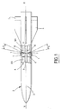
- FIG. 1 schematically illustrates, in partial longitudinal section, a missile equipped with actuation devices of the invention, for its piloting.
- Figure 2 shows, in section, a schematic embodiment of an actuating device according to the invention, in its inactive operating configuration.
- FIG. 2A shows an enlargement of a detail of the device illustrated in FIG. 2.
- FIG. 3 shows, similarly, the device of Figure 2 in its active operating configuration.
- Figures 4 and 5 illustrate exterior views, in two perpendicular planes, of a concrete embodiment of the actuating device, in the inactive configuration, for controlling an adjustable nozzle skirt.
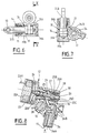
- Figures 6 and 7 are respectively sectional views of the device along lines VI-VI and VII-VII of Figure 4.
- Figures 8 and 9 are respectively sectional views of the device along lines VIII-VIII and IX-IX of Figure 5.
- FIG. 10 is a section of the device along the line X-X of FIG. 6.
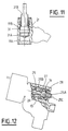
- Figures 11 and 12 are views similar to those of Figures 7 and 8, in the active configuration of said device.
- Figure 13 is a side view of Figure 9, showing the orientation of the skirt of the nozzle, as a result of actuation of the device.
- the actuating device 1 according to the invention will be described below with regard to its preferred application relating to the force piloting of a missile 2 shown diagrammatically in FIG. 1.
- This missile 2 comprises an elongated structure 3 of axis XX equipped, in the usual manner, with wings 4 provided with control surfaces 5.
- a block 6 for the piloting the missile in force comprising lateral nozzles 7, for example four in number, two to two diametrically opposite.
- the control unit 6 is located between two combustion chambers 8A of a gas generator 8, preferably with solid propellant.
- the side nozzles 7 are connected to the generator chambers by conduits 9 and each of them is advantageously controlled by an actuating device 1 according to the invention.
- this device makes it possible to act, when it is stressed, on a mechanical member 10 whose purpose is to deflect the gas jet leaving the lateral nozzle and coming from the combustion chambers of the gas generator, to then modify the trajectory of the missile.
- the actuating device 1 shown schematically in Figures 2 and 3, comprises a single body 11 which is intended, in this application, to be fixed to the structure 3 of the missile and in which are arranged on the one hand a distributor of control 12 and, on the other hand, an actuating cylinder 14 of said member to be moved by articulation means 13.
- a first conduit 15 connects a chamber 16 of the distributor 12 to an inlet orifice 17 of the body, which is in direct communication with the gas jet delivered by the gas generator.
- a second conduit 18 connects the chamber 16 of the distributor with a first chamber 19A of the jack 14. Depending on the inactive or active state of the distributor, this second conduit 18 can be in communication, via the chamber 16 of the distributor , with the first conduit 15 or with an outlet orifice 20 of the body in connection with the surrounding external environment.
- a third conduit 21 finally connects the second chamber 19B of the jack to the inlet orifice 17 of the body.
- the distributor 12 consists of a controllable electromagnet 22A, connected by a link 22A1 to a power supply (not shown), and of a displaceable element 22B extending the electromagnet axially.
- This the latter is housed in a casing 23 which is connected, by screwing, to said body 11.
- the movable element 22B is constituted, in known manner, by a pallet 24, turned towards the electromagnet and housed in the bottom of the casing , and by a rod 25 integral with the pallet 24 and passing through the bottom of the casing to open coaxially in a passage 26 which is provided in said body 11 and in which the chamber 16 of the distributor 12 is formed.
- the rod 25 has, in the vicinity of its end opposite to that screwed onto the pallet, an annular shoulder 25A which is then located at the level of the chamber 16 of said passage 26.
- the shoulder 25A is thus capable of cooperating, depending on the sliding of the rod controlled by the electromagnet, either with an upstream surface 27 of said passage, through which the first conduit 15 opens, or with a downstream surface 28 of said passage communicating with the outlet orifice 20 of the body.
- the chamber 16 of the distributor is then delimited by the upstream and downstream ranges 27, 28 of the passage, while the second conduit 18 opens laterally into the latter while being in communication either with the first conduit 15 or with the outlet orifice 20.
- the diameter Dt of the rod 25 is slightly smaller than the identical internal diameters d of the upstream 27 and downstream 28 bearings of the passage, and that the diameter D of said shoulder 25A is greater, but slightly, than the identical internal diameters d of the upstream 27 and downstream 28 bearings of the passage 26, which are defined, for example, by rings 29, 30 fixedly engaged in said passage.
- the rod 25 thus passes through the rings 29.30 and the shoulder 25A is located between them.
- conical surfaces 25B and 25C terminate the two sides of the shoulder, so that optimum sealing is obtained when one or the other of the conical surfaces 25B and 25C is in abutment, by the sliding of the rod, against the corresponding bearing.
- the displacement stroke of the sliding element 25, and therefore of the shoulder of the rod between the rings depending on whether the electromagnet is excited or not.
- the outlet orifice 20 is coaxial with the passage 26 of the dispenser and it is advantageously defined by the downstream annular ring 30.
- the outlet orifice 20 widens further towards the outside.
- the rod 25 ends in a cylindrical endpiece 25D extending the shoulder 25A by having a diameter close to, but less than, the latter. This nozzle 25D engages in the outlet orifice 20 of the body, defined by the downstream ring 30.
- the actuating cylinder 14 comprises a piston 31 capable of sliding with sealing in the chambers 19A and 19B formed by a passage 19 formed in the body. More particularly, the piston 31 consists of a head 31A sealingly separating the two chambers 19A and 19B and a rod 31B extending the head from the side of the second chamber 19B and projecting outwardly relative to the body 11 , to be associated with the member to be controlled by connecting means 13, as will be seen later.
- the rod 31B and, therefore, the member to be controlled are external to the gas jet and are not, therefore, in contact with the latter.
- Seals 32 are provided on the one hand around the head 31A of the piston and, on the other hand, around the rod 31B and they are produced, due to the temperatures and pressures present, with a material resistant to graphite base. Furthermore, it can be seen in FIGS. 2 and 3 that the cross section S of the first chamber 19A in communication with the second conduit 18 is optimal, since it corresponds to the transverse surface of the head 31A of the piston, and greater than the cross section s of the second chamber 19B in communication with the third conduit 21, since it corresponds to the difference between the cross section of the head 31A and the section transverse of the rod 31B.
- FIGS. 2 and 3 The schematic representation of the actuating device 1, illustrated in FIGS. 2 and 3, advantageously makes it possible to view on the same section plane the electromagnetic distributor 12, the jack 14 and the various conduits and passages provided in the body 11.
- the embodiment of the device 1 turns out to be quite different, as can be seen in FIGS. 4 and 5 showing the external contour of the actuating device 1, the distributor 12 of which is recognized and the jack 14 arranged in the same single body 11, which is associated with one of the side nozzles 7 of the force control block 6 of the missile 2.
- the numerical references assigned to the different parts of the device described in the figures 2 and 3 have been kept for the device described in FIGS. 6 to 10.
- this concrete embodiment of the actuating device 1 shows the member to be moved 10 by through the actuator, as well as other specific details of the device which will be described below.
- the member 10 making it possible to deflect, if necessary, the gas jet coming from the generator and passing through the lateral nozzle 7 is defined, in this example, by a skirt 10A substantially of frustoconical shape, which surrounds the downstream end 7A of the nozzle to extend beyond the latter, its upstream end 7B communicating with the conduit 9.
- the frustoconical skirt 10A is pivotally mounted relative to the nozzle 7 about an orthogonal axis 10B to the longitudinal axis LL of said nozzle.
- the skirt is, moreover, provided with a yoke in the form of a yoke 10C which straddles the end of the rod 31B of said piston so as to be associated with it by the connecting means 13, defined by an axis, parallel to the pivot axis 10B.
- the inlet orifice 17 of the gas jet is provided with a cylindrical ferrule 34 fixedly housed in the body and provided with an axial channel 34A in connection with the conduit 9 and opening out laterally in annular grooves 34B interconnected to then communicate with the first supply duct 15 of the distributor 12 and the third supply duct 21 of the second chamber 19B.
- the purpose of the arrangement of this ferrule is to brake and cool the gas jet generated by the generators in the direction of the force control block 6 consisting of the actuating devices 1 and the side nozzles 7.
- each device 1 is initially in the inactive configuration shown in Figures 2 and 4 to 10, for which the trajectory of the missile 2 is not changed.
- the electromagnet 22A is supplied, by the link 22A1, and attracts the movable element 22B towards it.
- the conical section 25B of the shoulder 25A provided on the rod 25 integral with the pallet 24, is applied against the upstream bearing 27 of the ring 29, closing the passage 26 and, in particular, the communication between the first conduit 15 and the chamber 16 of the distributor. Consequently, the flow of the gas jet, passing through the channel 34A and the grooves 34B of the shell 34, then the first conduit 15 to open into the passage 26, is stopped at the level of the shoulder contact 25A - ring 29.
- the chamber 16 of the distributor places the first chamber 19A of the jack in communication with the outside, respectively by the second conduit 18 and the outlet orifice 20 of the body. Simultaneously with the supply of the first conduit 15, the gas jet passes through the third conduit 21, so that the piston 31, under the action of the pressure exerted on its surface s then prevailing in the second chamber 19B, is pushed back until it occupies a retracted position by emptying the first chamber 19A in communication with the outside. Consequently, in the retracted position of the jack 14, obtained when the distributor 12 is supplied, corresponds a first, neutral position, of the skirt 10A, in the axial extension of the lateral nozzle 7, not influencing the trajectory of the missile.
- the orientable skirt 10A, the articulation means 13 and the rod part 31B leaving said body towards the outside environment are not affected by the gas jet emitted.
- the chamber 16 of the distributor and the first chamber 19A of the jack are isolated from the hot gas jet, avoiding the risks of deformation or the like, as long as the electromagnetic distributor 12 closes the first supply conduit 15.
- the low difference between the diameter Dt of the rod 25A and the diameter d of the upstream seat 27 requires only an effort minimum of the electromagnet, so that it can have a reduced size and, therefore, a small footprint.
- the electromagnet 22A of the distributor 11 is no longer supplied by the link 22A1.
- This supply break instantly causes a natural movement away from the movable element 22B which is no longer attracted by the electromagnet, thanks to the gas jet leaving the first conduit 15 towards the passage 26.
- the rod 25 is pushed back until the conical surface 25C of the shoulder 25A comes to bear against the downstream bearing 28 of the ring 30.
- the displacement of the rod 25 on the stroke c then establishes the fluid communication between the first conduit 15 and the second conduit 18 through the chamber 16 of the distributor, since the conical surface 25B of the shoulder has moved away, from the stroke c , from the upstream surface 27 of the ring 29.
- the contact between the conical surface 29C of the shoulder and the downstream surface 28 of the ring closes the outlet or exhaust port 20 of the distributor, and thus cuts the communication between the second conduit 18 and the latter.
- the gas jet after having passed through the first conduit 15, the chamber 16 and the second conduit 18, enters the first chamber 19A of the jack 14, so that the pressure of the gas jet is established in the two chambers 19A and 19B by the respective conduits 18 and 21.
- the piston 31 slides in the passage 19 towards its extended position, so that its rod 31B causes, by means of the articulation 13, the pivoting, in this case, of the orientable skirt 10A of the lateral nozzle 7 around the axis 10B.
- the device 1 then occupies its active configuration shown in FIGS. 3, 11 and 12, for which the member to be controlled, such as the skirt 10A, is in a second position, deviated by an angle ⁇ relative to the axis LL of the lateral nozzle 7, as shown in FIGS. 1 and 13, which thus makes it possible to modify the trajectory of missile 1.
- the member to be controlled such as the skirt 10A
- the flow of the hot gas jet in the device is carried out only sequentially, during the flight phases of the missile requiring abrupt modifications of its trajectory, and that the control force of the sliding element by the electromagnet is minimal due to the close diameters between the rod and the bearings and is only necessary in one direction of movement, towards the downstream range of the distributor .
- the production of a single body, bringing together the actuator and the distributor generates a significant gain in bulk.
- the member to be controlled could be different, and be, for example, in the form of another type of nozzle, a fin, a control surface and the like.
Landscapes
- Physics & Mathematics (AREA)
- Fluid Mechanics (AREA)
- Engineering & Computer Science (AREA)
- General Engineering & Computer Science (AREA)
- Aiming, Guidance, Guns With A Light Source, Armor, Camouflage, And Targets (AREA)
- Actuator (AREA)
- Jet Pumps And Other Pumps (AREA)
- Radar Systems Or Details Thereof (AREA)
Applications Claiming Priority (2)
| Application Number | Priority Date | Filing Date | Title |
|---|---|---|---|
| FR9215488 | 1992-12-22 | ||
| FR9215488A FR2699610B1 (fr) | 1992-12-22 | 1992-12-22 | Dispositif d'actionnement d'un organe mécanique, notamment pour le pilotage en force d'un missile, et missile équipé dudit dispositif. |
Publications (2)
| Publication Number | Publication Date |
|---|---|
| EP0604263A1 true EP0604263A1 (de) | 1994-06-29 |
| EP0604263B1 EP0604263B1 (de) | 1997-05-21 |
Family
ID=9436926
Family Applications (1)
| Application Number | Title | Priority Date | Filing Date |
|---|---|---|---|
| EP93402963A Expired - Lifetime EP0604263B1 (de) | 1992-12-22 | 1993-12-08 | Stellglied zur Bewegung einer schwenkbaren Raketendüse |
Country Status (5)
| Country | Link |
|---|---|
| US (1) | US5405103A (de) |
| EP (1) | EP0604263B1 (de) |
| DE (1) | DE69310884T2 (de) |
| ES (1) | ES2102627T3 (de) |
| FR (1) | FR2699610B1 (de) |
Cited By (2)
| Publication number | Priority date | Publication date | Assignee | Title |
|---|---|---|---|---|
| FR2730303A1 (fr) * | 1995-02-03 | 1996-08-09 | Loral Vought Systems Corp | Procede pour changer rapidement la direction de deplacement d'un vehicule, notamment d'un missile et machine pour sa mise en oeuvre |
| US6308911B1 (en) | 1998-10-30 | 2001-10-30 | Lockheed Martin Corp. | Method and apparatus for rapidly turning a vehicle in a fluid medium |
Families Citing this family (5)
| Publication number | Priority date | Publication date | Assignee | Title |
|---|---|---|---|---|
| US5755401A (en) * | 1995-10-31 | 1998-05-26 | Thiokol Corporation | Missile diverter integration method and system |
| US6315239B1 (en) * | 1997-09-23 | 2001-11-13 | Versatron, Inc. | Variable coupling arrangement for an integrated missile steering system |
| FR2870932B1 (fr) * | 2004-05-27 | 2006-08-11 | Mbda France Sa | Engin volant pour l'observation du sol |
| RU2280231C1 (ru) * | 2004-12-14 | 2006-07-20 | Государственное унитарное предприятие "Конструкторское бюро приборостроения" | Блок рулевого привода управляемого снаряда |
| RU2591005C1 (ru) * | 2015-01-21 | 2016-07-10 | Открытое Акционерное Общество "Государственный Ракетный Центр Имени Академика В.П. Макеева" | Привод рулевой |
Citations (3)
| Publication number | Priority date | Publication date | Assignee | Title |
|---|---|---|---|---|
| US3091084A (en) * | 1959-05-04 | 1963-05-28 | Pneumo Dynamics Corp | Solid propellant control system |
| US4078495A (en) * | 1974-08-15 | 1978-03-14 | The United States Of America As Represented By The Secretary Of The Navy | Control after burnout for reaction steered missiles |
| US5028014A (en) * | 1988-11-15 | 1991-07-02 | Anderson Jr Carl W | Radial bleed total thrust control apparatus and method for a rocket propelled missile |
Family Cites Families (3)
| Publication number | Priority date | Publication date | Assignee | Title |
|---|---|---|---|---|
| FR2588372B1 (fr) * | 1985-10-08 | 1989-07-13 | Thomson Brandt Armements | Dispositif de pilotage pour projectile guide au moyen de tuyeres laterales |
| DE3838100A1 (de) * | 1988-11-10 | 1990-05-17 | Messerschmitt Boelkow Blohm | Fluidverteiler |
| FR2659733B1 (fr) * | 1990-03-14 | 1994-07-01 | Aerospatiale | Systeme pour le pilotage d'un missile au moyen de tuyeres laterales. |
-
1992
- 1992-12-22 FR FR9215488A patent/FR2699610B1/fr not_active Expired - Fee Related
-
1993
- 1993-12-08 EP EP93402963A patent/EP0604263B1/de not_active Expired - Lifetime
- 1993-12-08 ES ES93402963T patent/ES2102627T3/es not_active Expired - Lifetime
- 1993-12-08 DE DE69310884T patent/DE69310884T2/de not_active Expired - Fee Related
- 1993-12-14 US US08/167,416 patent/US5405103A/en not_active Expired - Lifetime
Patent Citations (3)
| Publication number | Priority date | Publication date | Assignee | Title |
|---|---|---|---|---|
| US3091084A (en) * | 1959-05-04 | 1963-05-28 | Pneumo Dynamics Corp | Solid propellant control system |
| US4078495A (en) * | 1974-08-15 | 1978-03-14 | The United States Of America As Represented By The Secretary Of The Navy | Control after burnout for reaction steered missiles |
| US5028014A (en) * | 1988-11-15 | 1991-07-02 | Anderson Jr Carl W | Radial bleed total thrust control apparatus and method for a rocket propelled missile |
Cited By (4)
| Publication number | Priority date | Publication date | Assignee | Title |
|---|---|---|---|---|
| FR2730303A1 (fr) * | 1995-02-03 | 1996-08-09 | Loral Vought Systems Corp | Procede pour changer rapidement la direction de deplacement d'un vehicule, notamment d'un missile et machine pour sa mise en oeuvre |
| FR2779246A1 (fr) * | 1995-02-03 | 1999-12-03 | Loral Vought Systems Corp | Procede et systeme pour changer rapidement la direction de deplacement d'un vehicule se deplacant dans un milieu fluide |
| USRE37331E1 (en) | 1995-02-03 | 2001-08-14 | Lockheed Martin Corporation | Dual-control scheme for improved missile maneuverability |
| US6308911B1 (en) | 1998-10-30 | 2001-10-30 | Lockheed Martin Corp. | Method and apparatus for rapidly turning a vehicle in a fluid medium |
Also Published As
| Publication number | Publication date |
|---|---|
| DE69310884D1 (de) | 1997-06-26 |
| EP0604263B1 (de) | 1997-05-21 |
| ES2102627T3 (es) | 1997-08-01 |
| DE69310884T2 (de) | 1997-10-02 |
| FR2699610A1 (fr) | 1994-06-24 |
| US5405103A (en) | 1995-04-11 |
| FR2699610B1 (fr) | 1995-02-10 |
Similar Documents
| Publication | Publication Date | Title |
|---|---|---|
| EP0870105B1 (de) | Ausfahrbare raketentriebwerkdüse | |
| EP0117806B1 (de) | Flüssigkeitsverteiler, insbesondere für Fernsteuerung | |
| EP2143928B1 (de) | Einspritzvorrichtung für Monoergol mit starker Durchflussmodulation | |
| EP0604263B1 (de) | Stellglied zur Bewegung einer schwenkbaren Raketendüse | |
| EP1045130B1 (de) | Allseitig schwenkbare konvergente - divergente Schubdüse mit einem kardanischen Bedienungsring | |
| EP0064433B1 (de) | Lenkbarer Flugkörper | |
| EP2143929B1 (de) | Raketentriebwerk umfassend eine Einspritzvorrichtung für Monergol mit modulierbarem Durchfluss und stabiler Einspritzgeschwindigkeit | |
| EP1045129B1 (de) | Allseitig schwenkbare konvergente - divergente Schubdüse | |
| EP3026310B1 (de) | Elektromagnetisches Ventil für kryogenes Hochdruckgas | |
| WO2014135786A1 (fr) | Tuyere a section de col variable de propulseur d'engin aerospatial munie d'un pointeau mobile | |
| EP0653603B1 (de) | Vorrichtung zum gleichzeitigen Ausstossen von zwei Flüssigkeiten, insbesondere pyrotechnischen Flüssigkeiten | |
| EP0859301B1 (de) | Pneumatischer Druckreduzierregler | |
| FR2933743A1 (fr) | Dispositif d'injection de biergol a debit modulable. | |
| FR2740106A1 (fr) | Dispositif pour le pilotage d'engin spatial par vannage de gaz par tuyere mobile | |
| EP1101030A1 (de) | Kompaktes, veränderliches schubrohr zur steuerung von flugkörpern | |
| WO2000045039A1 (fr) | Systeme d'activation de tuyere orientable pour propulseur a reaction utilisant plusieurs ensembles elastiques repartis circonferentiellement | |
| WO2000045040A1 (fr) | Systeme d'activation de tuyere orientable par anneau elastique pour propulseur a reaction | |
| EP0153253B1 (de) | Hydraulisches Hochdruckwegeventil mit mechanisch steuerbarem Auslassventil | |
| EP0601912B1 (de) | Dreistellungszylinder | |
| FR2702526A1 (fr) | Dispositif d'assemblage en rotation d'un bras ou analogue avec et entre deux branches d'une pièce en forme de fourche. | |
| EP0233806B1 (de) | Schubdüse mit regelbarem Querschnitt | |
| BE1011007A3 (fr) | Vanne en ligne autoverrouillable. | |
| EP0561697B1 (de) | Verteilungsdüse für Flüssigkeiten | |
| WO1996018070A1 (fr) | Bruleur muni d'un dispositif de commande synchronise | |
| FR3151069A1 (fr) | vanne pour fluide cryotechnique |
Legal Events
| Date | Code | Title | Description |
|---|---|---|---|
| PUAI | Public reference made under article 153(3) epc to a published international application that has entered the european phase |
Free format text: ORIGINAL CODE: 0009012 |
|
| AK | Designated contracting states |
Kind code of ref document: A1 Designated state(s): BE CH DE ES GB IE IT LI NL SE |
|
| 17P | Request for examination filed |
Effective date: 19940722 |
|
| 17Q | First examination report despatched |
Effective date: 19951004 |
|
| GRAG | Despatch of communication of intention to grant |
Free format text: ORIGINAL CODE: EPIDOS AGRA |
|
| GRAH | Despatch of communication of intention to grant a patent |
Free format text: ORIGINAL CODE: EPIDOS IGRA |
|
| GRAH | Despatch of communication of intention to grant a patent |
Free format text: ORIGINAL CODE: EPIDOS IGRA |
|
| GRAA | (expected) grant |
Free format text: ORIGINAL CODE: 0009210 |
|
| AK | Designated contracting states |
Kind code of ref document: B1 Designated state(s): BE CH DE ES GB IE IT LI NL SE |
|
| REG | Reference to a national code |
Ref country code: CH Ref legal event code: NV Representative=s name: JOHN P. MUNZINGER INGENIEUR-CONSEIL Ref country code: CH Ref legal event code: EP |
|
| GBT | Gb: translation of ep patent filed (gb section 77(6)(a)/1977) |
Effective date: 19970522 |
|
| REF | Corresponds to: |
Ref document number: 69310884 Country of ref document: DE Date of ref document: 19970626 |
|
| REG | Reference to a national code |
Ref country code: ES Ref legal event code: FG2A Ref document number: 2102627 Country of ref document: ES Kind code of ref document: T3 |
|
| PLBE | No opposition filed within time limit |
Free format text: ORIGINAL CODE: 0009261 |
|
| STAA | Information on the status of an ep patent application or granted ep patent |
Free format text: STATUS: NO OPPOSITION FILED WITHIN TIME LIMIT |
|
| 26N | No opposition filed | ||
| REG | Reference to a national code |
Ref country code: GB Ref legal event code: IF02 |
|
| REG | Reference to a national code |
Ref country code: CH Ref legal event code: PCAR Free format text: JOHN P. MUNZINGER C/O CRONIN INTELLECTUAL PROPERTY;CHEMIN DE PRECOSSY 31;1260 NYON (CH) |
|
| PGFP | Annual fee paid to national office [announced via postgrant information from national office to epo] |
Ref country code: NL Payment date: 20071219 Year of fee payment: 15 Ref country code: ES Payment date: 20071211 Year of fee payment: 15 |
|
| PGFP | Annual fee paid to national office [announced via postgrant information from national office to epo] |
Ref country code: CH Payment date: 20071108 Year of fee payment: 15 |
|
| PGFP | Annual fee paid to national office [announced via postgrant information from national office to epo] |
Ref country code: SE Payment date: 20071212 Year of fee payment: 15 Ref country code: BE Payment date: 20071203 Year of fee payment: 15 |
|
| PGFP | Annual fee paid to national office [announced via postgrant information from national office to epo] |
Ref country code: GB Payment date: 20071109 Year of fee payment: 15 |
|
| PGFP | Annual fee paid to national office [announced via postgrant information from national office to epo] |
Ref country code: IT Payment date: 20071228 Year of fee payment: 15 Ref country code: DE Payment date: 20071130 Year of fee payment: 15 |
|
| BERE | Be: lapsed |
Owner name: *AEROSPATIALE SOC. NATIONALE INDUSTRIELLE Effective date: 20081231 |
|
| REG | Reference to a national code |
Ref country code: CH Ref legal event code: PL |
|
| EUG | Se: european patent has lapsed | ||
| GBPC | Gb: european patent ceased through non-payment of renewal fee |
Effective date: 20081208 |
|
| PGFP | Annual fee paid to national office [announced via postgrant information from national office to epo] |
Ref country code: IE Payment date: 20071108 Year of fee payment: 15 |
|
| NLV4 | Nl: lapsed or anulled due to non-payment of the annual fee |
Effective date: 20090701 |
|
| REG | Reference to a national code |
Ref country code: IE Ref legal event code: MM4A |
|
| PG25 | Lapsed in a contracting state [announced via postgrant information from national office to epo] |
Ref country code: BE Free format text: LAPSE BECAUSE OF NON-PAYMENT OF DUE FEES Effective date: 20081231 |
|
| PG25 | Lapsed in a contracting state [announced via postgrant information from national office to epo] |
Ref country code: LI Free format text: LAPSE BECAUSE OF NON-PAYMENT OF DUE FEES Effective date: 20081231 Ref country code: IE Free format text: LAPSE BECAUSE OF NON-PAYMENT OF DUE FEES Effective date: 20081208 Ref country code: DE Free format text: LAPSE BECAUSE OF NON-PAYMENT OF DUE FEES Effective date: 20090701 Ref country code: CH Free format text: LAPSE BECAUSE OF NON-PAYMENT OF DUE FEES Effective date: 20081231 |
|
| PG25 | Lapsed in a contracting state [announced via postgrant information from national office to epo] |
Ref country code: NL Free format text: LAPSE BECAUSE OF NON-PAYMENT OF DUE FEES Effective date: 20090701 Ref country code: GB Free format text: LAPSE BECAUSE OF NON-PAYMENT OF DUE FEES Effective date: 20081208 |
|
| REG | Reference to a national code |
Ref country code: ES Ref legal event code: FD2A Effective date: 20081209 |
|
| PG25 | Lapsed in a contracting state [announced via postgrant information from national office to epo] |
Ref country code: ES Free format text: LAPSE BECAUSE OF NON-PAYMENT OF DUE FEES Effective date: 20081209 |
|
| PG25 | Lapsed in a contracting state [announced via postgrant information from national office to epo] |
Ref country code: SE Free format text: LAPSE BECAUSE OF NON-PAYMENT OF DUE FEES Effective date: 20081209 |
|
| PG25 | Lapsed in a contracting state [announced via postgrant information from national office to epo] |
Ref country code: IT Free format text: LAPSE BECAUSE OF NON-PAYMENT OF DUE FEES Effective date: 20081208 |