EP0604312A1 - Elastischer Ring mit Fertiganzeige für eine Verbindung - Google Patents
Elastischer Ring mit Fertiganzeige für eine Verbindung Download PDFInfo
- Publication number
- EP0604312A1 EP0604312A1 EP93403134A EP93403134A EP0604312A1 EP 0604312 A1 EP0604312 A1 EP 0604312A1 EP 93403134 A EP93403134 A EP 93403134A EP 93403134 A EP93403134 A EP 93403134A EP 0604312 A1 EP0604312 A1 EP 0604312A1
- Authority
- EP
- European Patent Office
- Prior art keywords
- sleeve
- ring
- tab
- shoulder
- tightening
- Prior art date
- Legal status (The legal status is an assumption and is not a legal conclusion. Google has not performed a legal analysis and makes no representation as to the accuracy of the status listed.)
- Granted
Links
- 238000006073 displacement reaction Methods 0.000 claims description 6
- 230000000717 retained effect Effects 0.000 claims description 5
- 239000012530 fluid Substances 0.000 claims description 3
- 230000008878 coupling Effects 0.000 abstract 3
- 238000010168 coupling process Methods 0.000 abstract 3
- 238000005859 coupling reaction Methods 0.000 abstract 3
- 230000001747 exhibiting effect Effects 0.000 abstract 1
- 241000287107 Passer Species 0.000 description 1
- 230000006378 damage Effects 0.000 description 1
- 230000000694 effects Effects 0.000 description 1
- 230000000977 initiatory effect Effects 0.000 description 1
- 238000012544 monitoring process Methods 0.000 description 1
- 231100000331 toxic Toxicity 0.000 description 1
- 230000002588 toxic effect Effects 0.000 description 1
Images

Classifications
-
- F—MECHANICAL ENGINEERING; LIGHTING; HEATING; WEAPONS; BLASTING
- F16—ENGINEERING ELEMENTS AND UNITS; GENERAL MEASURES FOR PRODUCING AND MAINTAINING EFFECTIVE FUNCTIONING OF MACHINES OR INSTALLATIONS; THERMAL INSULATION IN GENERAL
- F16L—PIPES; JOINTS OR FITTINGS FOR PIPES; SUPPORTS FOR PIPES, CABLES OR PROTECTIVE TUBING; MEANS FOR THERMAL INSULATION IN GENERAL
- F16L19/00—Joints in which sealing surfaces are pressed together by means of a member, e.g. a swivel nut, screwed on, or into, one of the joint parts
- F16L19/005—Joints in which sealing surfaces are pressed together by means of a member, e.g. a swivel nut, screwed on, or into, one of the joint parts comprising locking means for the threaded member
Definitions
- the present invention relates to a sealed connection for a pipe for transporting any fluid, of the type comprising two parts with cooperating ends, respectively convex and concave and joined by an internally threaded sleeve, said sleeve having an annular internal shoulder intended to retain the one of the parts and being tightened by screwing on an external thread provided on the other part, braking means being provided to prevent loosening of the sleeve.
- Such a connector is known in particular from document FR-A-2 660 983 which provides on the threaded part of the sleeve a thinned and deformed zone to ensure clamping by self-braking of the part in the sleeve.
- fittings used in particular in aviation are equipped with means preventing the accidental loosening of said fittings, means making it possible to ensure a second seal if the previous ban is crossed, means to ensure that during assembly, said fittings have been properly tightened and means to indicate that said fittings are loose.
- US-A-3,325,192 proposes a pipe connection with a tightening indicator emerging from the nut following a subsequent deformation of the tightening adjustment piece. it is not obvious that this tightening indicator makes it possible to signal a subsequent accidental release.
- this connector does not include means for achieving a second seal in the event of loosening.
- FR-A-2 421 300 shows a device for fixing a wheel by screw or nut to a vehicle means in which an axially elastic washer provided with at least one axial extension is provided between the screw head and the wheel outside in the direction opposite to the axial displacement of the screw or nut caused by tightening.
- This axial extension comprises a terminal means which fits into the screw or nut when the axial crushing of the washer corresponds to the desired clamping force and the at least partial destruction of which warns of a wheel loosening. This document does not suggest having such a washer in a pipe fitting.
- the object of the present invention is to provide a fitting equipped with braking means intended to prevent the loosening of the sleeve, and which also fulfill the other desired functions, namely: a second seal in the event of loosening and the function of tightening indicator or loosening.
- said braking means comprise an elastic ring interposed between the annular shoulder of the sleeve and the part retained by said shoulder, and by the fact that said ring is provided with at least one tab which extends between said sleeve and said part in the general direction opposite to the axial displacement of the sleeve caused by tightening, said ring being capable of flattening when tightening said sleeve and said tab having a length such that the free end of said tab spring on the end face of said sleeve located on the side of said part, when said sleeve is tightened.
- the part retained by the sleeve has between the end face of said sleeve and said shoulder a conical wall whose diameter increases in the direction of axial displacement of the sleeve caused by tightening.
- said ring In the absence of tightening stress, said ring has a generally conical shape, its outer edge being located on the side of said shoulder and said tab is disposed in the vicinity of said conical wall, the flattening of said ring as a result of tightening causing the pivoting of said tab towards said sleeve.
- the elastic ring prevents accidental loosening of the sleeve.
- the tabs When tightening, the tabs will come out at the back of the sleeve. They constitute the visible testimony of tightening.
- the elastic ring In case of accidental loosening of the sleeve, the elastic ring returns to its initial shape, and pushes the part retained in the sleeve against the other part to ensure a second seal.
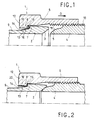
- a tight fitting 1 essentially comprising a first part 2 with concave end 3, a second part 4 with convex end 5 conjugate with the concave end of the first part 1, and a concentric outer sleeve 6 to parts 2 and 4 and allowing the tightening of these two parts 2 and 4 end to end and one against the other by their conjugate convex and concave ends 3 and 5.
- the first part 2, received in the sleeve 6, comprises, opposite its concave end 3, a shoulder 7 by which it bears on an annular inner shoulder 8 of the sleeve 6.
- a pipe not shown , may be fixed by any appropriate means to the end 9 of the first part 2.
- the second part 4, to which another pipe (not shown) can also be fixed, by any suitable means, has an external thread 10 capable of cooperating with a thread 11 provided inside the sleeve 6.
- the sleeve 6 has, on the side opposite the thread 11, an end face 12.
- the first part 2 has, opposite the sleeve part between the end face 12 and the shoulder 8, a conical wall 13, the diameter increases in the direction of axial displacement D of the sleeve 6 caused by tightening.
- an annular cavity 14 is thus formed between the conical wall 13 and the sleeve 6, this cavity opening onto the end face 12 of the sleeve 6.
- an elastic ring 15 for friction braking which comprises at least one lug 16 which is disposed in the cavity 14 and which extends towards the end face 12 of the sleeve 6.
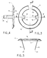
- the ring 15 is formed by an open washer of generally conical shape whose external edge 17, in the absence of tightening stress, is situated on the side of the shoulder 8 of the sleeve 6 and whose inner edge 18 is located in the angle formed by the shoulder 7 of the first part 2 and the conical wall 12.
- the legs 16 extend perpendicular to the wall of the ring 15 and in the absence of tightening stress, they rest on the conical wall 12 of the first part 2.
- the ring 15 flattens between the shoulders 7 and 8, the tabs 16 then pivot around the inner edge 18 and come to bear against the inner wall 19 of the sleeve 6 when the tightening torque is sufficient.
- the length of the legs 16 is calculated in such a way that their ends 20 come out on the end face 12 of the sleeve 6.
- the ring 15 tends to return to its initial shape due to its elasticity. This results in a reverse pivoting of the legs 16 which move away from the inner wall 19 of the sleeve 6 and approach the conical wall 12. In addition, their ends 20 are erased in the cavity 14. The legs 16 thus constitute witnesses tightening or loosening the sleeve 6.
- the elastic ring 15 also makes it possible to seal the connection 1, in the event of partial loosening, because it exerts a force on the first part 1 in the direction of the arrow D which maintains the end 3 of said first part 2 sealingly bears on end 5 of second part 4.
- the washer 15 is not open but it has a plurality of radial slots intended to reduce its hardness.
- the elastic ring 15 is formed of a closed washer having undulations which are crushed when tightened.
- the braking effect can be reinforced with this type of ring if the surfaces of the shoulders 7 and 8 are slightly wavy in the same way.
- the corrugated ring 15 also includes tabs 16 which extend axially towards the end wall 12 and which are housed in axial grooves 21 formed in the internal wall 19 of the sleeve 6.
- the end 20 of the legs 16 is curved outwards.
- the end 20 of the tabs spring out on the end face 12, owing to the fact that the elastic ring 15 is crushed by acting as a nut brake.
- the ends 20 constitute the tightening indicators.
- the corrugated elastic washer returns to its initial shape and presses the first part 2 onto the second part 4.
- the ring 15 and the sleeve 6 are thus trapped one from the other.
Landscapes
- Engineering & Computer Science (AREA)
- General Engineering & Computer Science (AREA)
- Mechanical Engineering (AREA)
- Bolts, Nuts, And Washers (AREA)
- Mutual Connection Of Rods And Tubes (AREA)
- Gasket Seals (AREA)
Applications Claiming Priority (2)
| Application Number | Priority Date | Filing Date | Title |
|---|---|---|---|
| FR9215540A FR2699644B1 (fr) | 1992-12-23 | 1992-12-23 | Bague élastique avec témoin de mise en contrainte pour raccord. |
| FR9215540 | 1992-12-23 |
Publications (2)
| Publication Number | Publication Date |
|---|---|
| EP0604312A1 true EP0604312A1 (de) | 1994-06-29 |
| EP0604312B1 EP0604312B1 (de) | 1996-09-25 |
Family
ID=9436971
Family Applications (1)
| Application Number | Title | Priority Date | Filing Date |
|---|---|---|---|
| EP93403134A Expired - Lifetime EP0604312B1 (de) | 1992-12-23 | 1993-12-22 | Elastischer Ring mit Fertiganzeige für eine Verbindung |
Country Status (4)
| Country | Link |
|---|---|
| US (1) | US5340163A (de) |
| EP (1) | EP0604312B1 (de) |
| DE (1) | DE69305057T2 (de) |
| FR (1) | FR2699644B1 (de) |
Families Citing this family (34)
| Publication number | Priority date | Publication date | Assignee | Title |
|---|---|---|---|---|
| FR2717883B1 (fr) * | 1994-03-04 | 1996-06-14 | Hutchinson | Dispositif de raccordement rapide et étanche pour conduites tubulaires. |
| RU2159384C2 (ru) * | 1996-01-17 | 2000-11-20 | Гудвин А. Лайкен | Прокладка для труб (варианты) |
| US6116658A (en) * | 1997-11-12 | 2000-09-12 | General Electric Company | Counter torque tube connection |
| US6890005B1 (en) * | 1999-10-29 | 2005-05-10 | Hutchinson Fts, Inc. | Self-centering tubular connection |
| US6193283B1 (en) | 1999-10-29 | 2001-02-27 | Automotive Fluid Systems, Inc. | Conduit and block connection indicator device |
| DE10022515A1 (de) * | 2000-05-10 | 2001-11-15 | Neumo Armaturenfabrik Appbau M | Verbindung für medienführende Teile |
| US6517126B1 (en) * | 2000-09-22 | 2003-02-11 | General Electric Company | Internal swage fitting |
| US6835088B2 (en) | 2001-06-20 | 2004-12-28 | Cooper Industries, Inc. | EMT rain-tight compression fittings |
| US6604762B2 (en) * | 2001-06-22 | 2003-08-12 | Clark Equipment Company | Hydraulic fitting |
| DE10206684B4 (de) * | 2002-02-18 | 2007-06-28 | Peter Pisinger | Klemmverschraubung |
| US7600789B2 (en) | 2002-07-24 | 2009-10-13 | Vyse Gerrard N | Lockwireless anti-rotation fitting |
| US6857665B2 (en) * | 2002-07-24 | 2005-02-22 | Parker-Hannifin Corporation | Lockwireless anti-rotation fitting |
| US6715297B1 (en) | 2002-09-20 | 2004-04-06 | General Electric Company | Methods and apparatus for supporting high temperature ducting |
| CN100588865C (zh) * | 2007-01-24 | 2010-02-10 | 马可系统分析和发展有限公司 | 接头件 |
| US7507117B2 (en) * | 2007-04-14 | 2009-03-24 | John Mezzalingua Associates, Inc. | Tightening indicator for coaxial cable connector |
| US7749022B2 (en) * | 2007-04-14 | 2010-07-06 | John Mezzalingua Associates, Inc. | Tightening indicator for coaxial cable connector |
| WO2008154076A1 (en) * | 2007-06-12 | 2008-12-18 | Cameron International Corporation | Connector system and method of connecting |
| US9772056B2 (en) * | 2009-03-05 | 2017-09-26 | Gates Corporation | Tube connector |
| US8857863B1 (en) | 2010-08-04 | 2014-10-14 | Supreme Service & Specialty Co., Inc. | Method and apparatus for connecting conduit |
| JP5360619B2 (ja) * | 2011-12-12 | 2013-12-04 | Smc株式会社 | 管継手 |
| US9383046B2 (en) * | 2013-03-14 | 2016-07-05 | Uniweld Products, Inc. | High pressure fitting |
| KR20150013985A (ko) * | 2013-07-24 | 2015-02-06 | 주식회사 콜러노비타 | 온수세정기의 분기 연결구 |
| KR101523176B1 (ko) * | 2014-10-31 | 2015-05-26 | 김기년 | 파이프 연결장치 |
| JP2016094963A (ja) * | 2014-11-12 | 2016-05-26 | トヨタ自動車株式会社 | 配管用継手構造 |
| JP5984098B1 (ja) * | 2015-03-13 | 2016-09-06 | Smc株式会社 | 管継手 |
| DE102015122309A1 (de) * | 2015-12-18 | 2017-06-22 | Voss Fluid Gmbh | Rohrverbindung |
| US10006568B2 (en) | 2016-06-06 | 2018-06-26 | United Technologies Corporation | Double walled tube and manufacture thereof |
| IT201700100297A1 (it) * | 2017-09-07 | 2019-03-07 | Ali Group Srl Carpigiani | Kit di connessione ed unita’ di alimentazione prodotti comprendente detto kit. |
| CN109099237A (zh) * | 2018-09-28 | 2018-12-28 | 苏州丹顿机电有限公司 | 一种管接头 |
| DE102019118901A1 (de) * | 2019-07-12 | 2021-01-14 | Voss Fluid Gmbh | "Montagevorrichtung für Rohrleitungen" |
| CN112066096B (zh) * | 2020-08-31 | 2022-04-29 | 浙江亚德复合材料有限公司 | 一种便于实时监测的管道 |
| CN114484101A (zh) * | 2021-12-27 | 2022-05-13 | 武汉航空仪表有限责任公司 | 一种可快速拆装的压力密封接口工艺装备 |
| CN116518169B (zh) * | 2023-06-07 | 2025-05-16 | 上海涵鲲科技有限公司 | 一种自锁管接头 |
| CN117989475A (zh) * | 2024-03-13 | 2024-05-07 | 西安西热锅炉环保工程有限公司 | 一种尿素产品氨气泄漏检测仪 |
Citations (6)
| Publication number | Priority date | Publication date | Assignee | Title |
|---|---|---|---|---|
| DE255090C (de) * | ||||
| DE453724C (de) * | 1925-05-12 | 1927-12-15 | Paul G Ehrhardt | Pressring zur Unterlage unter Schrauben und Muttern |
| DE546576C (de) * | 1932-03-16 | Draegerwerk Ag | Gegen selbsttaetiges Loesen gesicherte Schlauch- oder Rohrkupplung | |
| GB2027835A (en) * | 1978-08-10 | 1980-02-27 | Illinois Tool Works | Pressambled fastener units for clamping plastics workpieces |
| EP0384923A1 (de) * | 1989-02-28 | 1990-09-05 | Erico Elektrotechnische Spezialfabrik GmbH | Klemmscheibe für Schraubenbefestigung od. dgl. |
| FR2660983A1 (fr) * | 1990-04-12 | 1991-10-18 | Simmonds Sa | Raccord etanche indesserrable. |
Family Cites Families (10)
| Publication number | Priority date | Publication date | Assignee | Title |
|---|---|---|---|---|
| US2404142A (en) * | 1940-09-14 | 1946-07-16 | Logansport Machine Inc | Tube coupling |
| US2475741A (en) * | 1943-01-06 | 1949-07-12 | Robert A Goeller | Connector |
| DE835541C (de) * | 1949-11-17 | 1952-04-03 | Hans H Kreidel | Dichtung fuer Rohrverschraubungen |
| US3325192A (en) * | 1964-11-19 | 1967-06-13 | Parker Hannifin Corp | Flareless tube coupling nut and ferrule assembly |
| US4150847A (en) * | 1976-06-04 | 1979-04-24 | Cenzo Herbert A De | Flexible tube coupling with symmetrical anchor ring |
| FR2421300A1 (fr) * | 1978-03-29 | 1979-10-26 | Michelin & Cie | Dispositif de fixation par vis et ecrou |
| US4346918A (en) * | 1979-05-07 | 1982-08-31 | Lycan Goodwin A | Pipe spacer used in welding |
| US4522433A (en) * | 1982-05-14 | 1985-06-11 | Stanley Aviation Corporation | Spherical seat flexible O-ring coupling |
| US4655159A (en) * | 1985-09-27 | 1987-04-07 | Raychem Corp. | Compression pressure indicator |
| US5280967A (en) * | 1992-03-27 | 1994-01-25 | Donald Travis | Device for indicating the proper installation of fittings |
-
1992
- 1992-12-23 FR FR9215540A patent/FR2699644B1/fr not_active Expired - Fee Related
-
1993
- 1993-12-22 EP EP93403134A patent/EP0604312B1/de not_active Expired - Lifetime
- 1993-12-22 US US08/171,706 patent/US5340163A/en not_active Expired - Lifetime
- 1993-12-22 DE DE69305057T patent/DE69305057T2/de not_active Expired - Fee Related
Patent Citations (6)
| Publication number | Priority date | Publication date | Assignee | Title |
|---|---|---|---|---|
| DE255090C (de) * | ||||
| DE546576C (de) * | 1932-03-16 | Draegerwerk Ag | Gegen selbsttaetiges Loesen gesicherte Schlauch- oder Rohrkupplung | |
| DE453724C (de) * | 1925-05-12 | 1927-12-15 | Paul G Ehrhardt | Pressring zur Unterlage unter Schrauben und Muttern |
| GB2027835A (en) * | 1978-08-10 | 1980-02-27 | Illinois Tool Works | Pressambled fastener units for clamping plastics workpieces |
| EP0384923A1 (de) * | 1989-02-28 | 1990-09-05 | Erico Elektrotechnische Spezialfabrik GmbH | Klemmscheibe für Schraubenbefestigung od. dgl. |
| FR2660983A1 (fr) * | 1990-04-12 | 1991-10-18 | Simmonds Sa | Raccord etanche indesserrable. |
Also Published As
| Publication number | Publication date |
|---|---|
| DE69305057D1 (de) | 1996-10-31 |
| EP0604312B1 (de) | 1996-09-25 |
| FR2699644A1 (fr) | 1994-06-24 |
| US5340163A (en) | 1994-08-23 |
| FR2699644B1 (fr) | 1995-01-20 |
| DE69305057T2 (de) | 1997-02-06 |
Similar Documents
| Publication | Publication Date | Title |
|---|---|---|
| EP0604312B1 (de) | Elastischer Ring mit Fertiganzeige für eine Verbindung | |
| EP1064489B1 (de) | Steck-kupplung für rohre | |
| EP0791141B1 (de) | Selbstverriegelbare verschlussvorrichtung | |
| EP0441682B1 (de) | Abgedichtete Verbindung für fluidführende Rohrleitungen | |
| CA2360088C (fr) | Dispositif de raccordement rapide d'un tube a un element rigide | |
| EP0441683A1 (de) | Abgedichtete Verbindung für fluidführende Rohrleitungen | |
| FR2973003A1 (fr) | Dispositif d'obturation a verrouillage auto-activable | |
| FR2618870A1 (fr) | Collier de serrage pour le raccordement de deux tubes metalliques | |
| WO1997044243A1 (fr) | Systeme de blocage temporaire de deplacement de deux corps l'un par rapport a l'autre, suivant au moins un sens d'une direction predeterminee | |
| FR2651550A1 (fr) | Dispositif de tension de courroie d'entrainement ou analogue. | |
| EP2003384B1 (de) | Anschlusssystem, das Sicherheitsbefestigungselemente umfasst | |
| FR2482251A1 (fr) | Dispositif de raccordement d'un ecrou tournant a l'extremite d'un tuyau du type onduleux | |
| EP0452172A1 (de) | Schnellmontageclip für Wärmetauscher an Kraftfahrzeugen | |
| EP0508856A1 (de) | Sicherheitsbefestigungsanordnung für ein männliches Teil bie einem Bügel eines weiblichen Teils, verwendbar, insbesondere zum Verbinden von zwei Lenksäulenteilen eines Kraftfahrzeuges | |
| FR2605710A1 (fr) | Dispositif de raccordement, a connexion et deconnexion rapides, de conduites tubulaires | |
| EP0202156A1 (de) | Ringförmige Dichtungsanordnung, insbesondere für Klappen oder Ventile | |
| FR2805482A1 (fr) | Piece mecanique de transmission | |
| EP0323338B1 (de) | Vorrichtung zur Verbindung von zwei zurückversetzten Flanschen bei der Montage von Abgasrohren | |
| EP0085010A2 (de) | Selbstschliessende Kupplung insbesondere für ein Fluid oder eine Kühlflüssigkeit | |
| FR2658878A1 (fr) | Dispositif de connexion rapide entre deux portions d'une timonerie, notamment pour vehicule automobile. | |
| FR2785263A1 (fr) | Dispositif de remplissage d'un reservoir de carburant de vehicule automobile | |
| EP0679827B1 (de) | Kupplungsvorrichtung für Hochdruckhydraulikkreislauf | |
| FR2938894A1 (fr) | Dispositif de raccordement a double etancheite. | |
| FR2567598A1 (fr) | Ensemble de poussee pour embrayage a friction de vehicule automobile, avec securite pour son transport | |
| FR2716250A1 (fr) | Dispositif de sécurité automatique pour installations industrielles ou domestiques de gaz. |
Legal Events
| Date | Code | Title | Description |
|---|---|---|---|
| PUAI | Public reference made under article 153(3) epc to a published international application that has entered the european phase |
Free format text: ORIGINAL CODE: 0009012 |
|
| 17P | Request for examination filed |
Effective date: 19940107 |
|
| AK | Designated contracting states |
Kind code of ref document: A1 Designated state(s): DE FR GB |
|
| GRAG | Despatch of communication of intention to grant |
Free format text: ORIGINAL CODE: EPIDOS AGRA |
|
| GRAH | Despatch of communication of intention to grant a patent |
Free format text: ORIGINAL CODE: EPIDOS IGRA |
|
| 17Q | First examination report despatched |
Effective date: 19960304 |
|
| GRAH | Despatch of communication of intention to grant a patent |
Free format text: ORIGINAL CODE: EPIDOS IGRA |
|
| GRAA | (expected) grant |
Free format text: ORIGINAL CODE: 0009210 |
|
| AK | Designated contracting states |
Kind code of ref document: B1 Designated state(s): DE FR GB |
|
| GBT | Gb: translation of ep patent filed (gb section 77(6)(a)/1977) |
Effective date: 19960925 |
|
| REF | Corresponds to: |
Ref document number: 69305057 Country of ref document: DE Date of ref document: 19961031 |
|
| PLBE | No opposition filed within time limit |
Free format text: ORIGINAL CODE: 0009261 |
|
| STAA | Information on the status of an ep patent application or granted ep patent |
Free format text: STATUS: NO OPPOSITION FILED WITHIN TIME LIMIT |
|
| 26N | No opposition filed | ||
| REG | Reference to a national code |
Ref country code: GB Ref legal event code: IF02 |
|
| REG | Reference to a national code |
Ref country code: FR Ref legal event code: TP Ref country code: FR Ref legal event code: CD |
|
| REG | Reference to a national code |
Ref country code: FR Ref legal event code: CD |
|
| PGFP | Annual fee paid to national office [announced via postgrant information from national office to epo] |
Ref country code: DE Payment date: 20061124 Year of fee payment: 14 |
|
| PGFP | Annual fee paid to national office [announced via postgrant information from national office to epo] |
Ref country code: GB Payment date: 20061127 Year of fee payment: 14 |
|
| PGFP | Annual fee paid to national office [announced via postgrant information from national office to epo] |
Ref country code: FR Payment date: 20061128 Year of fee payment: 14 |
|
| GBPC | Gb: european patent ceased through non-payment of renewal fee |
Effective date: 20071222 |
|
| PG25 | Lapsed in a contracting state [announced via postgrant information from national office to epo] |
Ref country code: DE Free format text: LAPSE BECAUSE OF NON-PAYMENT OF DUE FEES Effective date: 20080701 |
|
| REG | Reference to a national code |
Ref country code: FR Ref legal event code: ST Effective date: 20081020 |
|
| PG25 | Lapsed in a contracting state [announced via postgrant information from national office to epo] |
Ref country code: GB Free format text: LAPSE BECAUSE OF NON-PAYMENT OF DUE FEES Effective date: 20071222 |
|
| PG25 | Lapsed in a contracting state [announced via postgrant information from national office to epo] |
Ref country code: FR Free format text: LAPSE BECAUSE OF NON-PAYMENT OF DUE FEES Effective date: 20071231 |