EP0604324A1 - Kraftfahrzeugscheibenwischer mit Vorrichtung zum Verstellen der Ausrichtung des Wischblatts - Google Patents
Kraftfahrzeugscheibenwischer mit Vorrichtung zum Verstellen der Ausrichtung des Wischblatts Download PDFInfo
- Publication number
- EP0604324A1 EP0604324A1 EP93403163A EP93403163A EP0604324A1 EP 0604324 A1 EP0604324 A1 EP 0604324A1 EP 93403163 A EP93403163 A EP 93403163A EP 93403163 A EP93403163 A EP 93403163A EP 0604324 A1 EP0604324 A1 EP 0604324A1
- Authority
- EP
- European Patent Office
- Prior art keywords
- drive head
- adjustment
- ring
- washer
- axis
- Prior art date
- Legal status (The legal status is an assumption and is not a legal conclusion. Google has not performed a legal analysis and makes no representation as to the accuracy of the status listed.)
- Granted
Links
- 230000001154 acute effect Effects 0.000 claims abstract description 6
- 230000002093 peripheral effect Effects 0.000 claims abstract description 6
- 230000000295 complement effect Effects 0.000 claims abstract description 3
- 208000031968 Cadaver Diseases 0.000 description 6
- 230000007935 neutral effect Effects 0.000 description 5
- 238000012550 audit Methods 0.000 description 1
- 238000005266 casting Methods 0.000 description 1
- 230000000694 effects Effects 0.000 description 1
- 238000000034 method Methods 0.000 description 1
- 239000007787 solid Substances 0.000 description 1
Images

Classifications
-
- B—PERFORMING OPERATIONS; TRANSPORTING
- B60—VEHICLES IN GENERAL
- B60S—SERVICING, CLEANING, REPAIRING, SUPPORTING, LIFTING, OR MANOEUVRING OF VEHICLES, NOT OTHERWISE PROVIDED FOR
- B60S1/00—Cleaning of vehicles
- B60S1/02—Cleaning windscreens, windows or optical devices
- B60S1/04—Wipers or the like, e.g. scrapers
- B60S1/32—Wipers or the like, e.g. scrapers characterised by constructional features of wiper blade arms or blades
- B60S1/34—Wiper arms; Mountings therefor
- B60S1/3425—Constructional aspects of the arm
- B60S1/3445—Joints between elements
- B60S1/3459—Joints between elements the element being a mounting head and a shaft
- B60S1/3461—Joints between elements the element being a mounting head and a shaft with means to adjust the orientation of the head relative to shaft
-
- B—PERFORMING OPERATIONS; TRANSPORTING
- B60—VEHICLES IN GENERAL
- B60S—SERVICING, CLEANING, REPAIRING, SUPPORTING, LIFTING, OR MANOEUVRING OF VEHICLES, NOT OTHERWISE PROVIDED FOR
- B60S1/00—Cleaning of vehicles
- B60S1/02—Cleaning windscreens, windows or optical devices
- B60S1/04—Wipers or the like, e.g. scrapers
- B60S1/32—Wipers or the like, e.g. scrapers characterised by constructional features of wiper blade arms or blades
- B60S1/34—Wiper arms; Mountings therefor
-
- B—PERFORMING OPERATIONS; TRANSPORTING
- B60—VEHICLES IN GENERAL
- B60S—SERVICING, CLEANING, REPAIRING, SUPPORTING, LIFTING, OR MANOEUVRING OF VEHICLES, NOT OTHERWISE PROVIDED FOR
- B60S1/00—Cleaning of vehicles
- B60S1/02—Cleaning windscreens, windows or optical devices
- B60S1/04—Wipers or the like, e.g. scrapers
- B60S1/32—Wipers or the like, e.g. scrapers characterised by constructional features of wiper blade arms or blades
- B60S1/34—Wiper arms; Mountings therefor
- B60S1/3418—Wiper arms; Mountings therefor with means for additionally adjusting the wiper arm working position with respect to the surface to be wiped
Definitions
- the present invention relates to a motor vehicle windscreen wiper.
- the invention relates more particularly to a wiper of the type comprising a wiper arm, the drive head of which is fixed to the end portion of an output shaft belonging to a drive unit of the wiper.
- the end portion of the drive shaft has a conical section which is received in a complementary conical bore opening out from the drive head and which is extended by a threaded end section on which is tightened a tightening nut whose radial tightening face cooperates with a portion opposite in the upper face of the drive head.
- the axis of the conical bore is perpendicular to the upper and lower planar faces of the drive head of the wiper arm so that, in the mounted and clamped position, these two faces extend in planes perpendicular to the axis of rotation of the output shaft.
- This geometric arrangement determines the general orientation of the wiper arm, of the wiper blade which is articulated at the end of the arm and of the wiper blade carried by the wiper blade, by relative to the structure of the vehicle and therefore relative to the surface to be wiped such as the vehicle windshield.
- the invention provides a wiper of the type mentioned above, characterized in that it comprises adjustable means for varying the inclination of the axis of the conical bore relative to a reference plane of the head drive.
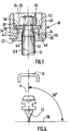
- the shaft 10 comprises, at its free end, a conical section 12, the apex angle of which is for example equal to 19 °, and which is extended by a threaded coaxial section 14.
- the drive shaft 10 is a rotary shaft about its axis XX so as to drive in a reciprocating rotational movement a wiper arm, a portion 16 of which is illustrated in FIGS. 4 to 6 and which comprises in this case effect a drive head 18 comprising a solid body 20 generally produced by casting in foundry.
- the rear portion of the drive head 18 illustrated in the figures which is intended to be connected to the output shaft 10, has a flat lower face 22 and an upper face 24 in which is formed a recess 26 whose bottom 28 is a portion of annular planar surface parallel to the lower surface 22.
- the surface portion 28 is therefore parallel to the lower face 22 which, within the meaning of the invention, constitutes the so-called reference plane for assessing the general orientation of the wiper arm relative to the axis XX and, indirectly, with respect to the surface to be wiped 30 with which a wiping blade 32 cooperates, connected, by a structure not shown, to the wiper arm 16.
- the body 20 of the drive head 18 has a cylindrical bore 34 which opens on the one hand into the lower face 22 and on the other hand into the annular surface portion 28.
- the axis of the cylindrical bore 34 is perpendicular to the reference plane 22.
- the means for mounting and clamping the drive head 18 on the end of the output shaft 10 comprises an adjustment ring 36.
- the adjusting ring or sleeve 36 has an outer peripheral surface 38 which is cylindrical and which is received in the bore 34.
- the body of the ring 36 is extended at its lower part by a radial collar 40, the upper face 42 of which is a radial face perpendicular to the axis Z-Z of the external cylindrical surface 38 and cooperates with the reference plane 22.
- a conical bore 44 Inside the ring 36 is formed a conical bore 44 whose angle at the top is substantially equal to that of the section 12 of the shaft 10 and for example at 19 °.
- the axis Y-Y of the conical bore 44 forms an acute angle with the axis Z-Z of the outer cylindrical surface 38 of the ring.
- This acute angle which constitutes the adjustment angle within the meaning of the invention, is for example equal to 4 °.
- the two axes YY and ZZ are concurrent at a point C located substantially at the level of the upper face 42 of the radial collar 40 and therefore situated substantially at the level of the reference plane 22 of the drive head 18, when the ring is in position mounted in bore 34.
- the upper face 46 of the ring 36 is a flat annular face perpendicular to the axis Z-Z and therefore parallel to the upper face 42 of the collar 40.
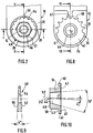
- the clamping means also include a washer 48 illustrated in FIG. 9.
- the lower 50 and upper 52 faces of the washer 48 are not parallel to each other but form an acute angle equal to the adjustment angle of the adjustment ring 36 and therefore, in the example illustrated in the figures, substantially equal to 4 °.
- the washer 48 has at its center a bore 54 to allow the passage of the threaded section 14 of the output shaft 10.
- the clamping means finally comprise a clamping nut 56 which is mounted screwed onto the threaded section 14 and whose lower radial clamping face 58 cooperates with the upper face 52 of the washer 48.
- the lower face 43 of the ring has a series of nine marks, from - 4 ° to + 4 °, which make it possible to regularly orient the adjustment ring relative to the body 20 of the drive head 18.
- a notch 60 is formed opposite each reference, in the lateral edge 41 of the radial collar 40, and the lower face 36 of the body 20 includes an indexing finger 62 which is designed to be received in one notches 60.
- the finger 62 is received in the notch 60 formed opposite the mark "0 °" which corresponds to the position for neutral adjustment of the orientation of the arm in which the reference plane 22 is perpendicular to the axis XX by considering FIG. 1.
- the upper face 52 of the adjustment washer 48 comprises a series of nine marks paired with notches 64 in which an indexing finger 66 produced integrally with the body 20 can be received.
- the washer 48 is, like the adjustment ring 36, indexed in the neutral position, that is to say corresponding to the adjustment mark "0 °".
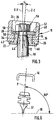
- the adjustment is carried out, prior to the final tightening operation of the nut 56, by modifying the angular position of the adjustment ring 36 and of the adjustment washer 48 relative to the body 20 of the drive head 18 .
- This orientation results in an inclination of the reference plane 22 relative to the position it occupied in FIG. 1 on which it is perpendicular to the axis X-X.
- FIGS. 3 and 6 A symmetrical adjustment is illustrated in FIGS. 3 and 6 corresponding to the indexing of the ring 36 and of the washer 48 on the marks - 4 °.
- This new adjustment causes an inclination of the reference plane 22 relative to the axis X-X which results in an inclination of + 86 ° of the median plane P of the wiping blade 32 relative to the surface to be wiped 30.
Landscapes
- Engineering & Computer Science (AREA)
- Mechanical Engineering (AREA)
- Moving Of Heads (AREA)
- Gears, Cams (AREA)
- Window Of Vehicle (AREA)
- Gear Transmission (AREA)
- Cleaning In General (AREA)
Applications Claiming Priority (2)
| Application Number | Priority Date | Filing Date | Title |
|---|---|---|---|
| FR9215639 | 1992-12-23 | ||
| FR9215639A FR2699483B1 (fr) | 1992-12-23 | 1992-12-23 | Essuie-glace de véhicule automobile comportant des moyens de réglage de l'orientation de la lame d'essuyage. |
Publications (2)
| Publication Number | Publication Date |
|---|---|
| EP0604324A1 true EP0604324A1 (de) | 1994-06-29 |
| EP0604324B1 EP0604324B1 (de) | 1997-03-12 |
Family
ID=9437052
Family Applications (1)
| Application Number | Title | Priority Date | Filing Date |
|---|---|---|---|
| EP19930403163 Expired - Lifetime EP0604324B1 (de) | 1992-12-23 | 1993-12-23 | Kraftfahrzeugscheibenwischer mit Vorrichtung zum Verstellen der Ausrichtung des Wischblatts |
Country Status (4)
| Country | Link |
|---|---|
| EP (1) | EP0604324B1 (de) |
| DE (1) | DE69308793T2 (de) |
| ES (1) | ES2101984T3 (de) |
| FR (1) | FR2699483B1 (de) |
Cited By (7)
| Publication number | Priority date | Publication date | Assignee | Title |
|---|---|---|---|---|
| EP0673813A1 (de) * | 1994-03-23 | 1995-09-27 | Paul Journee S.A. | Scheibenwischer für Kraftfahrzeuge mit Befestigungsteil-Orientierungsmittel |
| FR2729351A1 (fr) * | 1995-01-18 | 1996-07-19 | Peugeot | Ensemble d'essuie-glace pour vitre arriere de vehicule automobile |
| FR2735193A1 (fr) * | 1995-06-12 | 1996-12-13 | Soc D Rech D Etudes Et De Valo | Dispositif d'accouplement d'un cylindre creux a un arbre, destine a etre place en bout dudit arbre, la position angulaire relative du cylindre et de l'arbre etant reglable |
| FR2742112A1 (fr) * | 1995-12-07 | 1997-06-13 | Valeo Systemes Dessuyage | Essuie-glace de vehicule automobile muni d'un dispositif de reglage precis de sa position angulaire lors de son montage sur un vehicule |
| WO2000030907A1 (de) | 1998-11-25 | 2000-06-02 | Robert Bosch Gmbh | Wischblatt zum reinigen einer fahrzeugscheibe |
| US6550097B1 (en) * | 1999-06-29 | 2003-04-22 | Robert Bosch Gmbh | Wiper arm |
| WO2008040643A1 (de) | 2006-10-04 | 2008-04-10 | Robert Bosch Gmbh | Wischblatt zum reinigen einer scheibe |
Citations (5)
| Publication number | Priority date | Publication date | Assignee | Title |
|---|---|---|---|---|
| US3161902A (en) * | 1962-10-10 | 1964-12-22 | Trico Products Corp | Wiper arm |
| FR2250650A1 (en) * | 1973-11-13 | 1975-06-06 | Bosch Gmbh Robert | Motor vehicle windscreen wiper mounting - has safety catch operated by swinging aside protective cap |
| EP0021914A1 (de) * | 1979-06-13 | 1981-01-07 | DUCELLIER & Cie | Scheibenwischer, insbesondere für Kraftfahrzeuge |
| FR2563482A2 (fr) * | 1982-04-02 | 1985-10-31 | Marchal Equip Auto | Tete d'assemblage matricee d'un element d'essuie-glace, son procede de fabrication et element d'essuie-glace la comportant |
| EP0491603A1 (de) * | 1990-12-18 | 1992-06-24 | Valeo Systemes D'essuyage | Verbindungsglied zwischen einem Scheibenwischerarm, insbesondere für Kraftfahrzeug |
-
1992
- 1992-12-23 FR FR9215639A patent/FR2699483B1/fr not_active Expired - Fee Related
-
1993
- 1993-12-23 DE DE1993608793 patent/DE69308793T2/de not_active Expired - Fee Related
- 1993-12-23 EP EP19930403163 patent/EP0604324B1/de not_active Expired - Lifetime
- 1993-12-23 ES ES93403163T patent/ES2101984T3/es not_active Expired - Lifetime
Patent Citations (5)
| Publication number | Priority date | Publication date | Assignee | Title |
|---|---|---|---|---|
| US3161902A (en) * | 1962-10-10 | 1964-12-22 | Trico Products Corp | Wiper arm |
| FR2250650A1 (en) * | 1973-11-13 | 1975-06-06 | Bosch Gmbh Robert | Motor vehicle windscreen wiper mounting - has safety catch operated by swinging aside protective cap |
| EP0021914A1 (de) * | 1979-06-13 | 1981-01-07 | DUCELLIER & Cie | Scheibenwischer, insbesondere für Kraftfahrzeuge |
| FR2563482A2 (fr) * | 1982-04-02 | 1985-10-31 | Marchal Equip Auto | Tete d'assemblage matricee d'un element d'essuie-glace, son procede de fabrication et element d'essuie-glace la comportant |
| EP0491603A1 (de) * | 1990-12-18 | 1992-06-24 | Valeo Systemes D'essuyage | Verbindungsglied zwischen einem Scheibenwischerarm, insbesondere für Kraftfahrzeug |
Cited By (9)
| Publication number | Priority date | Publication date | Assignee | Title |
|---|---|---|---|---|
| EP0673813A1 (de) * | 1994-03-23 | 1995-09-27 | Paul Journee S.A. | Scheibenwischer für Kraftfahrzeuge mit Befestigungsteil-Orientierungsmittel |
| US5623742A (en) * | 1994-03-23 | 1997-04-29 | Paul Journee, S.A. | Motor vehicle screen wiper having means for orientation of the drive head |
| FR2729351A1 (fr) * | 1995-01-18 | 1996-07-19 | Peugeot | Ensemble d'essuie-glace pour vitre arriere de vehicule automobile |
| FR2735193A1 (fr) * | 1995-06-12 | 1996-12-13 | Soc D Rech D Etudes Et De Valo | Dispositif d'accouplement d'un cylindre creux a un arbre, destine a etre place en bout dudit arbre, la position angulaire relative du cylindre et de l'arbre etant reglable |
| WO1996041963A1 (fr) * | 1995-06-12 | 1996-12-27 | Societe De Recherches, D'etudes Et De Valorisation | Dispositif d'accouplement reglable |
| FR2742112A1 (fr) * | 1995-12-07 | 1997-06-13 | Valeo Systemes Dessuyage | Essuie-glace de vehicule automobile muni d'un dispositif de reglage precis de sa position angulaire lors de son montage sur un vehicule |
| WO2000030907A1 (de) | 1998-11-25 | 2000-06-02 | Robert Bosch Gmbh | Wischblatt zum reinigen einer fahrzeugscheibe |
| US6550097B1 (en) * | 1999-06-29 | 2003-04-22 | Robert Bosch Gmbh | Wiper arm |
| WO2008040643A1 (de) | 2006-10-04 | 2008-04-10 | Robert Bosch Gmbh | Wischblatt zum reinigen einer scheibe |
Also Published As
| Publication number | Publication date |
|---|---|
| FR2699483A1 (fr) | 1994-06-24 |
| DE69308793T2 (de) | 1997-06-19 |
| DE69308793D1 (de) | 1997-04-17 |
| EP0604324B1 (de) | 1997-03-12 |
| ES2101984T3 (es) | 1997-07-16 |
| FR2699483B1 (fr) | 1995-02-10 |
Similar Documents
| Publication | Publication Date | Title |
|---|---|---|
| EP0673813A1 (de) | Scheibenwischer für Kraftfahrzeuge mit Befestigungsteil-Orientierungsmittel | |
| CA2090937A1 (fr) | Ensemble de colonne de direction reglable en position pour vehicule automobile | |
| EP0832799B1 (de) | Kraftfahrzeugscheibenwischer mit einer verbesserten Vorrichtung zur Orientierung der Wischerwelle | |
| EP0781692A1 (de) | Scheibenwischer-Mechanismus mit Führungs-und Dichtungsmittel zur Antriebaxen-Durchquerung eines Bleches | |
| EP0807035A1 (de) | Kraftzeugscheibenwischvorrichtung | |
| EP0604324B1 (de) | Kraftfahrzeugscheibenwischer mit Vorrichtung zum Verstellen der Ausrichtung des Wischblatts | |
| EP0021914B1 (de) | Scheibenwischer, insbesondere für Kraftfahrzeuge | |
| EP0669237B1 (de) | Scheibenwischer mit verbesserten Verbindungsmitteln zwischen der Antriebswelle und dem Befestigungsteil | |
| EP0879971B1 (de) | Vorrichtung zur Befestigung einer Anordnung an einer Kraftfahrzeugkarosserie und Wischermodul mit einer derartigen Vorrichtung | |
| EP0491603B1 (de) | Verbindungsglied zwischen einem Scheibenwischerarm, insbesondere für Kraftfahrzeug | |
| EP0669236B1 (de) | Kraftfahrzeug-Scheibenwischer mit verbesserten Verbindungsmitteln zwischen dem Befestigungsteil und der rotierenden Antriebswelle | |
| EP0788950B1 (de) | Kraftfahrzeug-Scheibenwischervorrichtung mit Scheibenwischer-Indexierungsmittelnunter Berücksichtigung der Antriebswelle | |
| EP0739793B1 (de) | Scheibenwischeranlage für ein Kraftfahrzeug mit einem demontierbaren Strukturelement | |
| FR2716656A1 (fr) | Agencement de palier étanche pour le montage d'un arbre d'un mécanisme d'entraînement d'un essuie-glace. | |
| FR2774340A1 (fr) | Mecanisme d'essuie-glace de vehicule automobile | |
| EP0685657A1 (de) | Anordnung zur Montage bzw. Befestigung eines Aggregats an einem Wagenkasten, sowie Wischanlage mit einer derartigen Anordnung | |
| EP1331402A1 (de) | Steuereinrichtung für Statorschaufel | |
| FR2763296A1 (fr) | Systeme d'essuyage comportant un palier de guidage de l'arbre d'entrainement de l'essuie-glace | |
| FR2724891A1 (fr) | Platine-support pour un mecanisme d'essuie-glace | |
| FR2488558A1 (fr) | Essuie-glace notamment pour vehicule automobile | |
| FR2721275A1 (fr) | Agencement pour le montage pivotant d'un bras d'essuie-glace appartenant à un système d'essuyage à deux bras d'essuie-glace parallèles. | |
| FR2742112A1 (fr) | Essuie-glace de vehicule automobile muni d'un dispositif de reglage precis de sa position angulaire lors de son montage sur un vehicule | |
| FR2780366A1 (fr) | Systeme d'essuyage comportant un palier muni d'une surface de portee spherique | |
| FR2763297A1 (fr) | Systeme d'essuyage pour vehicule automobile comportant des moyens perfectionnes de guidage en rotation de l'essuie-glace | |
| FR2768978A1 (fr) | Dispositif d'entrainement pour un systeme d'essuie-glace de vehicule automobile comportant des moyens perfectionnes de fixation d'une rotule |
Legal Events
| Date | Code | Title | Description |
|---|---|---|---|
| PUAI | Public reference made under article 153(3) epc to a published international application that has entered the european phase |
Free format text: ORIGINAL CODE: 0009012 |
|
| AK | Designated contracting states |
Kind code of ref document: A1 Designated state(s): DE ES GB IT |
|
| 17P | Request for examination filed |
Effective date: 19941028 |
|
| 17Q | First examination report despatched |
Effective date: 19951123 |
|
| GRAG | Despatch of communication of intention to grant |
Free format text: ORIGINAL CODE: EPIDOS AGRA |
|
| GRAH | Despatch of communication of intention to grant a patent |
Free format text: ORIGINAL CODE: EPIDOS IGRA |
|
| GRAH | Despatch of communication of intention to grant a patent |
Free format text: ORIGINAL CODE: EPIDOS IGRA |
|
| GRAA | (expected) grant |
Free format text: ORIGINAL CODE: 0009210 |
|
| AK | Designated contracting states |
Kind code of ref document: B1 Designated state(s): DE ES GB IT |
|
| GBT | Gb: translation of ep patent filed (gb section 77(6)(a)/1977) |
Effective date: 19970313 |
|
| REF | Corresponds to: |
Ref document number: 69308793 Country of ref document: DE Date of ref document: 19970417 |
|
| ITF | It: translation for a ep patent filed | ||
| REG | Reference to a national code |
Ref country code: ES Ref legal event code: FG2A Ref document number: 2101984 Country of ref document: ES Kind code of ref document: T3 |
|
| PG25 | Lapsed in a contracting state [announced via postgrant information from national office to epo] |
Ref country code: GB Free format text: LAPSE BECAUSE OF NON-PAYMENT OF DUE FEES Effective date: 19971223 |
|
| PLBE | No opposition filed within time limit |
Free format text: ORIGINAL CODE: 0009261 |
|
| STAA | Information on the status of an ep patent application or granted ep patent |
Free format text: STATUS: NO OPPOSITION FILED WITHIN TIME LIMIT |
|
| 26N | No opposition filed | ||
| GBPC | Gb: european patent ceased through non-payment of renewal fee |
Effective date: 19971223 |
|
| PG25 | Lapsed in a contracting state [announced via postgrant information from national office to epo] |
Ref country code: DE Free format text: LAPSE BECAUSE OF NON-PAYMENT OF DUE FEES Effective date: 19980901 |
|
| PG25 | Lapsed in a contracting state [announced via postgrant information from national office to epo] |
Ref country code: ES Free format text: LAPSE BECAUSE OF NON-PAYMENT OF DUE FEES Effective date: 19981224 |
|
| REG | Reference to a national code |
Ref country code: ES Ref legal event code: FD2A Effective date: 19990114 |
|
| PG25 | Lapsed in a contracting state [announced via postgrant information from national office to epo] |
Ref country code: IT Free format text: LAPSE BECAUSE OF NON-PAYMENT OF DUE FEES Effective date: 20051223 |